
CNS 250 F - Heating STIEBEL ELTRON - Free user manual and instructions
Find the device manual for free CNS 250 F STIEBEL ELTRON in PDF.
| Product type | Wall-mounted electric natural convection heater |
| Brand | Stiebel Eltron |
| Model | CNS 250 F |
| Connection power | 2.5 kW |
| Power supply | 230 V, 1/N~ |
| Height | 450 mm |
| Width | 890 mm |
| Depth | 100 mm |
| Weight (series S) | 8.1 kg |
| Weight (series U) | 7.7 kg |
| Protection rating | IP24 |
| Protection class | II |
| Frost protection | 7 °C |
| Temperature setting range | 7 to 30 °C |
| Mounting type | Wall-mounted, fixed on a supplied wall bracket |
| Mains connection | Power connector (series S) or fixed connection with plug (series U) |
| Heating body material | Not specified but natural convection |
| Main functions | Adjustable thermostat, frost protection, temperature limitation by pins, manual shutdown |
| Maintenance and cleaning | Clean with a damp cloth, do not use spray or abrasive cleaners |
| Safety | Do not cover, minimum distances, safety thermostat, mandatory all-pole disconnection |
| Spare parts and repairability | Original power cable only, authorized installer for replacement |
| Warranty | According to the conditions of the local subsidiary in the country of purchase |
| Standards | Compliant with national and local regulations |
Frequently Asked Questions - CNS 250 F STIEBEL ELTRON
User questions about CNS 250 F STIEBEL ELTRON
0 question about this device. Answer the ones you know or ask your own.
Ask a new question about this device
Download the instructions for your Heating in PDF format for free! Find your manual CNS 250 F - STIEBEL ELTRON and take your electronic device back in hand. On this page are published all the documents necessary for the use of your device. CNS 250 F by STIEBEL ELTRON.
USER MANUAL CNS 250 F STIEBEL ELTRON
BEDIENUNG UND INSTALLATION OPERATION AND INSTALLATION UTILISATION ET INSTALLATION BEDIENING EN INSTALLATIE OBSŁUGA I INSTALACJA OBSLUHA A INSTALACE ЭКСПЛУАТАЦИЯ И МОНТАЖ HASZNÁLATI ÉS TELEPÍTÉSI ÚTMU UPRAVLJANJE IN NAMESTITEV
WANDKONVEKTOR | WALL MOUNTED CONVECTOR HEATER | CONVECTEUR MURAL | WANDCONVECTOR | KONWEKTOR WISZĄCY | NÁSTĚNNÝ KONVEKTOR | HACTEHHÝI ō KOHBEKTOP | FALI KONVEKTOR | STENSKI KONVEKTOR
natural_image
Blank rectangular frame with horizontal lines and a top header, no text or symbols presentBESONDERE HINWEISE
BEDIENUNG
natural_image
3D architectural or mechanical component diagram with no visible text or symbols1 Stift
2 Temperatur-Einstellknopf
1.1 Safety instructions 13
1.2 Other symbols in this documentation ____ 13
1.3 Information on the appliance 13
1.4 Units of measurement 13
- Safety 13
2.1 Intended use 13
2.2 General safety instructions 14
2.3 Test symbols 14
- Appliance description 14
3.1 Series CNS-S 14
3.2 Series CNS-U 14
- Operation 14
4.1 Description of the user interface 14
4.2 Frost protection 15
4.3 Limiting the temperature controller ____ 15
4.4 Shutdown 15
-
Cleaning, care and maintenance 15
-
What to do if... 15
INSTALLATION
- Safety 16
7.1 General safety instructions 16
7.2 Instructions, standards and regulations ____ 16
- Appliance description 16
8.1 Standard delivery 16
- Installation 16
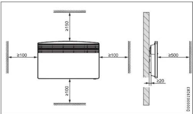
9.1 Minimum clearances 16
9.2 Installing the wall mounting bracket 16
9.3 Appliance installation 17
9.4 Removing the appliance 17
9.5 Power supply 17
-
Troubleshooting 17
-
Appliance handover 17
-
Specification 18
12.1 Dimensions and connections 18
12.2 Data table 18
GUARANTEE
ENVIRONMENT AND RECYCLING
SPECIAL INFORMATION
- Keep children under the age of 3 away from the appliance if constant supervision cannot be guaranteed.
- Children from the age of 3 to 7 may switch the appliance on and off, provided they are supervised or have been instructed in the safe operation of the appliance and understand any risks that may result. This is subject to the appliance having been installed as described. Children from the age of 3 to 7 must not plug the power cable into its socket nor regulate the appliance.
- The appliance may be used by children aged 8 and older and persons with reduced physical, sensory or mental capabilities or a lack of experience and know-how, provided that they are supervised or they have been instructed on how to use the appliance safely and have understood the resulting risks.
- Children must never play with the appliance. Children must never clean the appliance or perform user maintenance unless they are supervised.
- Parts of the appliance can get very hot and may cause burns. Particular caution is advised when children or vulnerable persons are present.
- In order to avoid overheating, do not cover the heater.
- Never install the appliance directly below a wall socket.
- Install the appliance in such a way that the control equipment cannot be touched by a person in the bath or shower.
- Ensure the appliance can be separated from the power supply by an isolator that disconnects all poles with at least 3 mm contact separation.
- The power cable may only be replaced (for example if damaged) by a qualified contractor authorised by the manufacturer, using an original spare part.
- Secure the appliance as described in chapter "Installation / Installation".
OPERATION
1. General information
The chapters "Special Information" and "Operation" are intended for both the user and qualified contractors.
The chapter "Installation" is intended for qualified contractors.

Note
Read these instructions carefully before using the appliance and retain them for future reference.
Pass on the instructions to a new user if required.
1.1 Safety instructions
1.1.1 Structure of safety instructions

KEYWORD Type of risk
Here, possible consequences are listed that may result from failure to observe the safety instructions.
▶ Steps to prevent the risk are listed.
1.1.2 Symbols, type of risk
Symbol Type of risk

Injury

Electrocution

Burns
(burns, scalding)
1.1.3 Keywords
KEYWORD Meaning
| DANGER | Failure to observe this information will result in serious injury or death. |
| WARNING | Failure to observe this information may result in serious injury or death. |
| CAUTION | Failure to observe this information may result in non-serious or minor injury. |
1.2 Other symbols in this documentation

Note
General information is identified by the adjacent symbol.
▶ Read these texts carefully.
Symbol Meaning

Material losses
(appliance damage, consequential losses and environmental pollution)
Appliance disposal

This symbol indicates that you have to do something. The action you need to take is described step by step.
1.3 Information on the appliance
Symbol Meaning

Never cover the appliance
1.4 Units of measurement

Note
All measurements are given in mm unless stated otherwise.
2. Safety
2.1 Intended use
This appliance is designed to heat living areas.
This appliance is intended for domestic use. It can be used safely by untrained persons. The appliance can also be used in a non-domestic environment, e.g. in a small business, as long as it is used in the same way.
Any other use beyond that described shall be deemed inappropriate. Observation of these instructions and of instructions for any accessories used is also part of the correct use of this appliance.
2.2 General safety instructions
Operate the appliance only when fully installed and with all safety equipment fitted.

WARNING Injury
- Keep children under the age of 3 away from the appliance if constant supervision cannot be guaranteed.
- Children from the age of 3 to 7 may switch the appliance on and off, provided they are supervised or have been instructed in the safe operation of the appliance and understand any risks that may result. This is subject to the appliance having been installed as described. Children from the age of 3 to 7 must not plug the power cable into its socket nor regulate the appliance.
- The appliance may be used by children aged 8 and older and persons with reduced physical, sensory or mental capabilities or a lack of experience and know-how, provided that they are supervised or they have been instructed on how to use the appliance safely and have understood the resulting risks.
- Children must never play with the appliance. Children must never clean the appliance or perform user maintenance unless they are supervised.

WARNING Burns
Never operate this appliance...
- in rooms where the appliance is at risk of fire or explosion as a result of chemicals, dust, gases or vapours.
- in the direct proximity of pipes or receptacles that
carry or contain flammable or explosive materials. - if work such as laying cables, grinding or sealing is carried out in the installation room.
- if sprays, floor polish or similar products containing napsan are used. Vent the room sufficiently before heating.
- if the minimum clearances to adjacent object surfaces are not maintained, for example to furniture, net curtains, curtains, textiles or other flammable materials.
- if an appliance component is damaged, the appliance has fallen over or already had a fault.

WARNING Burns
Never place any flammable, combustible or insulating objects or materials, such as laundry, blankets, magazines, containers with floor polish or napsan, spray cans or similar on the appliance or in direct proximity to it.

WARNING Burns
Parts of the appliance can get very hot and may cause burns. Particular caution is advised when children or vulnerable persons are present.

WARNING Overheating
In order to avoid overheating, do not cover the heater.

Material losses
Never step on the appliance.
2.3 Test symbols
See type plate located on the right on the exterior of the appliance.
3. Appliance description
The appliance is a wall mounted electric direct heater.
The appliance is suitable as a full heating system in bathrooms, for example, or for use between seasons and as a booster heater in smaller rooms, such as hobby and guest rooms.
The air in the appliance is heated by a heating element and expelled via natural convection through the air outlet grille at the top. Cool room air flows in through the apertures at the bottom of the appliance.
3.1 Series CNS-S
After mounting the appliance on the wall and making the electrical connection using a mains plug, the appliance is ready for operation.
3.2 Series CNS-U
After mounting the appliance on the wall and making the electrical connection using a permanent power supply via an appliance socket, the appliance is ready for operation.
4. Operation
4.1 Description of the user interface
▶ Switch the appliance ON via the switch on the r.h. side of the appliance.
▶ Set the required room temperature via the continuously variable temperature selector (for temperatures see specification chapter).
natural_image
Architectural floor plan of a building with visible foundation and window (no text or labels)As soon as the selected room temperature is reached, it is constantly maintained at this selected temperature through periodic heating (the output of the appliance must correspond at least to the required heat demand of the room).
If several appliances are installed in a single room, the setting at the temperature selector on each appliance can be different.

Note
To avoid excessive power consumption when windows are open, switch the appliance off while airing.
4.2 Frost protection
▶ Turn the temperature selector as far to the right as possible. In this position, the temperature controller switches on the heating element automatically if the room temperature drops below the frost protection temperature.
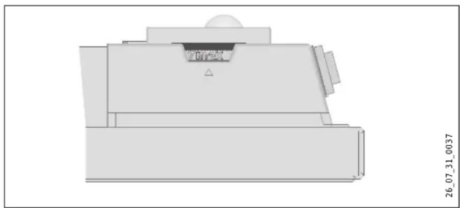
4.3 Limiting the temperature controller
Using the two pins fitted to the back of the control casing, you can fix the temperature controller at a certain setting or limit the temperature setting range.
▶ Break out the pins.
▶ To fix the selected temperature, push a pin into the hole opposite (see diagram).
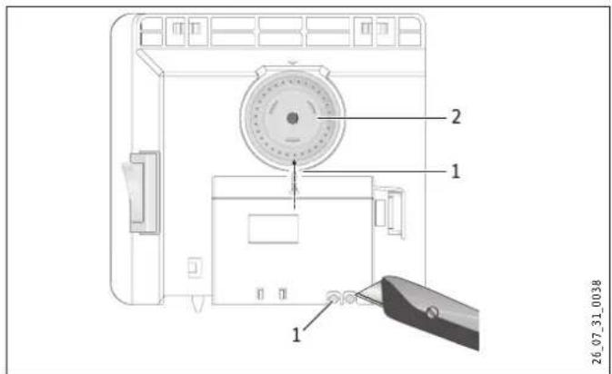
1 Pin
2 Temperature selector
▶ To limit the temperature setting range, set the minimum and maximum values at the temperature selector, and push a pin for each into the slightly offset hole opposite (see diagram).
5. Cleaning, care and maintenance

CAUTION Burns
Never spray cleaning spray into the air slot.
Ensure that no moisture can enter the appliance.
▶ If a pale brownish discolouration appears on the appliance casing, wipe it off with a damp cloth.
Clean the appliance when cold with ordinary cleaning products. Avoid abrasive or corrosive cleaning products.

Note
As part of regular maintenance, we recommend also having the control components checked. The safety and control components should be checked by a contractor no more than ten years after commissioning.
6. What to do if...
... the appliance does not heat up:
▶ Check the temperature set at the appliance and the MCB/fuse in your fuse box.
The appliance has a safety temperature controller that shuts the appliance down if it overheats. After the cause has been removed (for example air outlet or inlet apertures covered) and the appliance has cooled down for a few minutes, operation starts again.
If you cannot remedy the fault, contact your contractor. To facilitate and speed up your enquiry, please provide the number on the type plate (no. XXXXXX - XXXX - XXXXXX).
1 Pin
2 Temperature selector
4.4 Shutdown
▶ Move the switch on the right of the appliance to OFF.
INSTALLATION
7. Safety
Only a qualified contractor should carry out installation, commissioning, maintenance and repair of the appliance.
7.1 General safety instructions
We guarantee trouble-free function and operational reliability only if original accessories and spare parts intended for the appliance are used.

WARNING Electrocution
Install the appliance in such a way that control equipment cannot be touched by a person in the bath or shower.

Material losses
- Only fit the wall mounted appliance to a vertical wall that is temperature-resistant to at least 85 °C.
- Maintain the minimum clearances to adjacent object surfaces.
- Never install the appliance directly below a wall socket.
- Ensure that the power cable is not in contact with any appliance components.
7.2 Instructions, standards and regulations

Note
Observe all applicable national and regional regulations and instructions.
8. Appliance description
8.1 Standard delivery
The following are delivered with the appliance:
- Wall mounting bracket (hooked into the appliance)
9. Installation
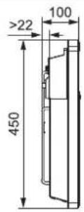
9.1 Minimum clearances
9.2 Installing the wall mounting bracket

Note
You can use the wall mounting bracket as a template for wall mounting; this ensures the required floor clearance.
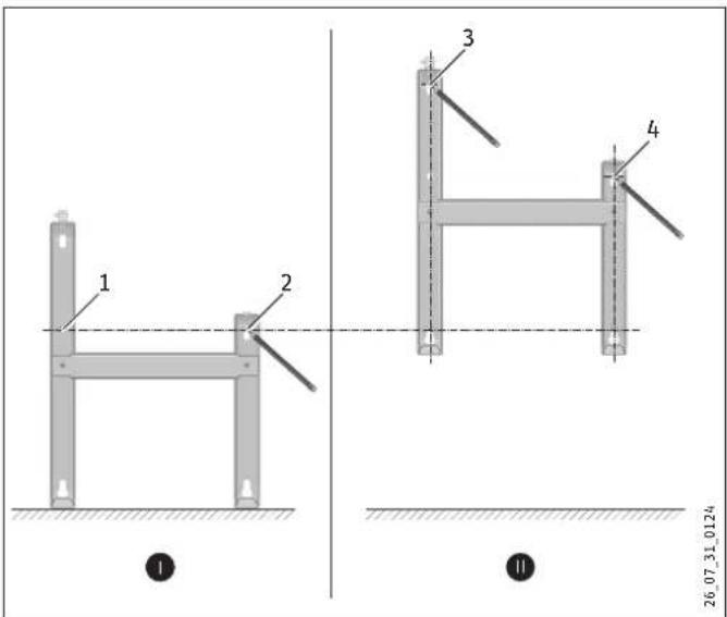
▶ Unhook the wall mounting bracket.
▶ Place the centred wall mounting bracket level on the ground and mark holes 1 and 2.
▶ Lift up the wall mounting bracket so that its lower holes match up with the markings you have just made on the installation wall.
▶ Mark holes 3 and 4 on the installation wall.
▶ Drill holes at all four markings. Secure the wall mounting bracket with suitable materials (screws, rawl plugs) depending on the type of wall. With the vertical slots, you can compensate for an offset fixing hole.
9.3 Appliance installation
▶ Hook the appliance by its slots in the back of the appliance on to all four tabs of the wall mounting bracket simultaneously.
▶ Push the appliance to latch it in position.
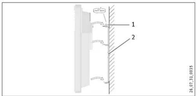
1 Locking bolt
2 Wall mounting bracket
▶ Turn the locking bolt in the wall mounting bracket fully clockwise; this locks the appliance in place.
9.5 Power supply
▶ Ensure the on-site supply cable has an adequate cross-section.
▶ When connecting the appliance via a standard socket, ensure that the socket is easily accessible once the appliance has been installed.

WARNING Electrocution
- Carry out all electrical connection and installation work in accordance with relevant regulations.
- Ensure the appliance can be separated from the power supply by an isolator that disconnects all poles with at least 3 mm contact separation.
- Do not install the appliance with a fixed power cable.

Note
Observe the type plate. The specified voltage must match the mains voltage.
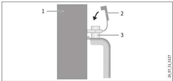
1 Appliance
2 Safety cap
3 Locking bolt
▶ Push the safety cap onto the locking bolt to prevent it from loosening.
10. Troubleshooting
The power cable must only be replaced by a contractor using our original spare parts.
11. Appliance handover
Explain the functions of the appliance to the user. Draw special attention to the safety instructions. Hand over the operating and installation instructions to the user.
9.4 Removing the appliance
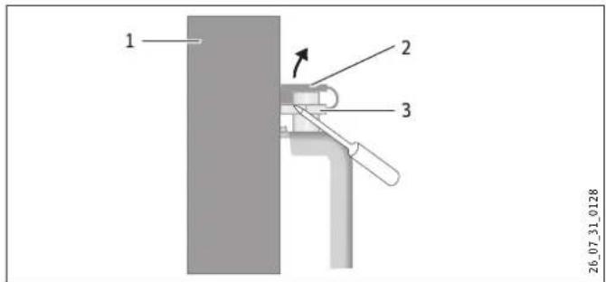
1 Appliance
2 Safety cap
3 Locking bolt
▶ Remove the safety cap from the locking bolt.
▶ Undo the locking bolt on the wall mounting bracket.
▶ Lift the appliance up slightly and pull it forwards and away
from the wall mounting bracket.
12. Specification
12.1 Dimensions and connections
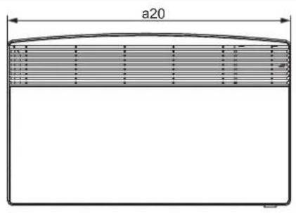
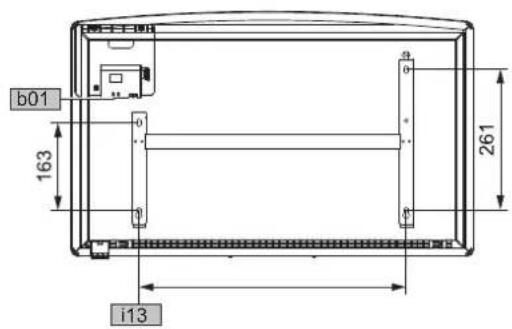
D0000019277
| CNS | 50 S/U | 75 S/U | 100 S/U | 125 S/U | 150 S/U | 175 S/U | 200 S/U | 250 S/U | 300 S/U | |||
| a20 | Appliance | Width | mm | 370 | 445 | 445 | 590 | 590 | 740 | 740 | 890 | 1040 |
| b01 | Electrical cable grommet | |||||||||||
| i13 | Wall mounting bracket | Hole spacing | mm | 121 | 195 | 195 | 343 | 343 | 491 | 491 | 639 | 787 |
12.2 Data table
CNS 50-300 S
| CNS 50 S | CNS 75 S | CNS 100 S | CNS 125 S | CNS 150 S | CNS 175 S | CNS 200 S | CNS 250 S | CNS 300 S | ||
| 220716 | 220717 | 220718 | 220719 | 220720 | 220721 | 220722 | 220723 | 220724 | ||
| Electrical data | ||||||||||
| Connected load | kW | 0.5 | 0.75 | 1.0 | 1.25 | 1.5 | 1.75 | 2.0 | 2.5 | 3.0 |
| Power supply | 1/N ~ 230 V | 1/N ~ 230 V | 1/N ~ 230 V | 1/N ~ 230 V | 1/N ~ 230 V | 1/N ~ 230 V | 1/N ~ 230 V | 1/N ~ 230 V | 1/N ~ 230 V | |
| Dimensions | ||||||||||
| Height | mm | 450 | 450 | 450 | 450 | 450 | 450 | 450 | 450 | 450 |
| Width | mm | 370 | 445 | 445 | 590 | 590 | 740 | 740 | 890 | 1040 |
| Depth | mm | 100 | 100 | 100 | 100 | 100 | 100 | 100 | 100 | 100 |
| Weights | ||||||||||
| Weight | kg | 3.8 | 4.4 | 4.4 | 5.7 | 5.7 | 6.8 | 6.8 | 8.1 | 9.4 |
| Versions | ||||||||||
| Frost protection setting | °C | 7 | 7 | 7 | 7 | 7 | 7 | 7 | 7 | 7 |
| IP rating | IP24 | IP24 | IP24 | IP24 | IP24 | IP24 | IP24 | IP24 | IP24 | |
| Protection class | II | II | II | II | II | II | II | II | II | |
| Colour | Alpine white | Alpine white | Alpine white | Alpine white | Alpine white | Alpine white | Alpine white | Alpine white | Alpine white | |
| Values | ||||||||||
| Setting range | °C | 7-30 | 7-30 | 7-30 | 7-30 | 7-30 | 7-30 | 7-30 | 7-30 | 7-30 |
CNS 50-300 U
| CNS 50 U | CNS 75 U | CNS 100 U | CNS 125 U | CNS 150 U | CNS 175 U | CNS 200 U | CNS 250 U | CNS 300 U | ||
| 220725 | 220726 | 220727 | 220728 | 220729 | 220730 | 220731 | 220732 | 220733 | ||
| Electrical data | ||||||||||
| Connected load | kW | 0.5 | 0.75 | 1.0 | 1.25 | 1.5 | 1.75 | 2.0 | 2.5 | 3.0 |
| Power supply | 1/N ~ 230 V | 1/N ~ 230 V | 1/N ~ 230 V | 1/N ~ 230 V | 1/N ~ 230 V | 1/N ~ 230 V | 1/N ~ 230 V | 1/N ~ 230 V | 1/N ~ 230 V | |
| Dimensions | ||||||||||
| Height | mm | 450 | 450 | 450 | 450 | 450 | 450 | 450 | 450 | 450 |
| Width | mm | 370 | 445 | 445 | 590 | 590 | 740 | 740 | 890 | 1040 |
| Depth | mm | 100 | 100 | 100 | 100 | 100 | 100 | 100 | 100 | 100 |
| Weights | ||||||||||
| Weight | kg | 3.3 | 4 | 4 | 5.2 | 5.2 | 6.3 | 6.3 | 7.7 | 8.9 |
| Versions | ||||||||||
| Frost protection setting | °C | 7 | 7 | 7 | 7 | 7 | 7 | 7 | 7 | 7 |
| IP rating | IP24 | IP24 | IP24 | IP24 | IP24 | IP24 | IP24 | IP24 | IP24 | |
| Protection class | II | II | II | II | II | II | II | II | II | |
| Colour | Alpine white | Alpine white | Alpine white | Alpine white | Alpine white | Alpine white | Alpine white | Alpine white | Alpine white | |
| Values | ||||||||||
| Setting range | °C | 7-30 | 7-30 | 7-30 | 7-30 | 7-30 | 7-30 | 7-30 | 7-30 | 7-30 |
Guarantee
The guarantee conditions of our German companies do not apply to appliances acquired outside of Germany. In countries where our subsidiaries sell our products a guarantee can only be issued by those subsidiaries. Such guarantee is only granted if the subsidiary has issued its own terms of guarantee. No other guarantee will be granted.
We shall not provide any guarantee for appliances acquired in countries where we have no subsidiary to sell our products. This will not affect warranties issued by any importers.
Environment and recycling
We would ask you to help protect the environment. After use, dispose of the various materials in accordance with national regulations.
REMARQUES PARTICULIÈRES
UTILISATION
natural_image
Architectural floor plan of a building with visible foundation and window (no text or labels)UTILISATION
26_07_31_0038
26_07_31_0171
WAARSCHUWING verbranding
WAARSCHUWING verbranding
WAARSCHUWING oververhitting
natural_image
3D architectural or mechanical component diagram with no visible text or symbols26_07_31_0038
natural_image
3D architectural or mechanical component diagram with no visible text or symbolsnatural_image
Pure technical diagram of a mechanical component without any text, numbers, or symbols26_07_31_0037
26_07_31_0038
natural_image
3D mechanical part diagram with no visible text or symbols26_07_31_0038
РУССКИЙ
natural_image
Pure technical diagram of a mechanical component without any text, numbers, or symbols26_07_31_0038
26_07_31_0171
natural_image
Pure technical diagram of a mechanical component without any text, numbers, or symbols26.07.31.0037
6 Prohasky Street | Port Melbourne VIC 3207
Tel. 03 9645-1833 | Fax 03 9645-4366
info@stiebel.com.au
www.stiebel.com.au
Austria
STIEBEL ELTRON Ges.m.b.H.
Rm 102, F1, Yingbin-Yihao Mansion, No. 1
Yingbin Road
Panyu District | 511431 Guangzhou
Tel. 020 39162209 | Fax 020 39162203
info@stiebeleltron.cn
www.stiebeleltron.cn
Czech Republic
STIEBEL ELTRON spol. s r.o.
Urzhumskaya street 4,
building 2 | 129343 Moscow
Tel. 0495 7753889 | Fax 0495 7753887
info@stiebel-eltron.ru
www.stiebel-eltron.ru
Slovakia
TATRAMAT - ohrievače vody s.r.o.
Hlavná 1 | 058 01 Poprad
Tel. 052 7127-125 | Fax 052 7127-148
info@stiebel-eltron.sk
www.stiebel-eltron.sk
Switzerland
STIEBEL ELTRON AG
Industrie West
Gass 8 | 5242 Lupfig
Tel. 056 4640-500 | Fax 056 4640-501
info@stiebel-eltron.ch
www.stiebel-eltron.ch
Thailand
STIEBEL ELTRON Asia Ltd.
469 Moo 2 Tambol Klong-Jik
Amphur Bangpa-In | 13160 Ayutthaya
Tel. 035 220088 | Fax 035 221188
info@stiebeleltronasia.com
www.stiebeleltronasia.com
United Kingdom and Ireland
STIEBEL ELTRON UK Ltd.
Unit 12 Stadium Court
Stadium Road | CH62 3RP Bromborough
Tel. 0151 346-2300 | Fax 0151 334-2913
info@stiebel-eltron.co.uk
www.stiebel-eltron.co.uk
United States of America
STIEBEL ELTRON, Inc.
17 West Street | 01088 West Hatfield MA
Tel. 0413 247-3380 | Fax 0413 247-3369
info@stiebel-eltron-usa.com
www.stiebel-eltron-usa.com
Irrtum und technische Änderungen vorbehalten! | Subject to errors and technical changes! | Sous réserve d'erreurs et de modifications techniques! | Onder voorbehoud van vergissingen en technische wijzigingen! | Salvo error o modificación técnica! | Excepto erro ou alteração técnica | Zastrzeżone zmiany techniczne i ewentualne błędy | Omyly a technické zmény jsou vyhrazeny! | A muszaki változtatások és tévedések jo gát fenntartjuk! | Отсутствие ошибok ne гарантируется. Возможны технические изменения. | Chýby a technické zmeny sü vyhradené! Stand 9147
STIEBEL ELTRON

- BESONDERE HINWEISE
- BEDIENUNG
- INSTALLATION
- GUARANTEE
- ENVIRONMENT AND RECYCLING
- SPECIAL INFORMATION
- OPERATION
- General information
- Note
- Safety instructions
- Structure of safety instructions
- KEYWORD Type of risk
- Symbols, type of risk
- Keywords
- Other symbols in this documentation
- Information on the appliance
- Units of measurement
- Safety
- Intended use
- General safety instructions
- WARNING Injury
- WARNING Burns
- WARNING Overheating
- Material losses
- Test symbols
- Appliance description
- Series CNS-S
- Series CNS-U
- Operation
- Description of the user interface
- Frost protection
- Limiting the temperature controller
- Cleaning, care and maintenance
- What to do if...
- Shutdown
- Safety
- General safety instructions
- WARNING Electrocution
- Instructions, standards and regulations
- Appliance description
- Standard delivery
- Installation
- Minimum clearances
- Installing the wall mounting bracket
- Appliance installation
- Power supply
- Troubleshooting
- Appliance handover
- Removing the appliance
- Specification
- Dimensions and connections
- Data table
- REMARQUES PARTICULIÈRES
- UTILISATION
- WAARSCHUWING verbranding
- WAARSCHUWING oververhitting
- Austria
- Czech Republic
- Slovakia
- Switzerland
- Thailand
- United Kingdom and Ireland
- United States of America
Brand : STIEBEL ELTRON
Model : CNS 250 F
Category : Heating