Before reading, unfold the page containing the illustrations and familiarise yourself with all functions of the device.
Intended use.. Page 34
Important product information.. Page 34
Scope of delivery.. Page 34
Parts description.. Page 35
Technical Data Page 35
General safety guidelines.. Page 35
Analyse error codes.. Page 36
Read out error codes.
Start error diagnosis
Call up menu functions.. Page 38
Delete diagnosed error codes.. Page 38
Menu function inspection program/exhaust system.. Page 38
Menu function read Vehicle Identification Number (VIN) Page 39
Menu function rescanning
Vehicle-diagnosed fault (DTC - Diagnosed Fault Code), install CD. Page 40
Make yourself familiar with all functions before first start-up of the equipment and gain inform you about correct
handling the device. Read for this the following operating manual carefully. Store this manual carefully. Pass on all documents also when passing on the device to third parties.
The OBD II diagnostic device is to be used for the reading and deletion of vehicle error codes in the on-board computer. This OBD II diagnostic device OL 8000 is suitable for petrol vehicles produced from year 2000 upwards and diesel vehicles from starting from 2003 upwards with a corresponding OBD II-connector socket. It is exclusively certified for the private use. All other use or change to the device is considered as not intended and bears substantial dangers. The manufacturer does not take over any liability for damages arising from unintended use.
The designation OBD II stands for non-board diagnostic system of the second generation and is used for the check of the data memory in vehicles.
The OBD II-system was developed to check emissions-systems and important electronic- and engine components.
When the malfunction indicator light "Malfunction Indicator Light" (MIL) lights up, the error code can be read using the OBD II-Device.
These diagnosed codes/malfunction messages (DTC = Diagnosed Trouble Codes) are displayed on the AEG OBD II diagnostic device. These error codes are transmitted from the vehicle data memory to the OBD II -device.
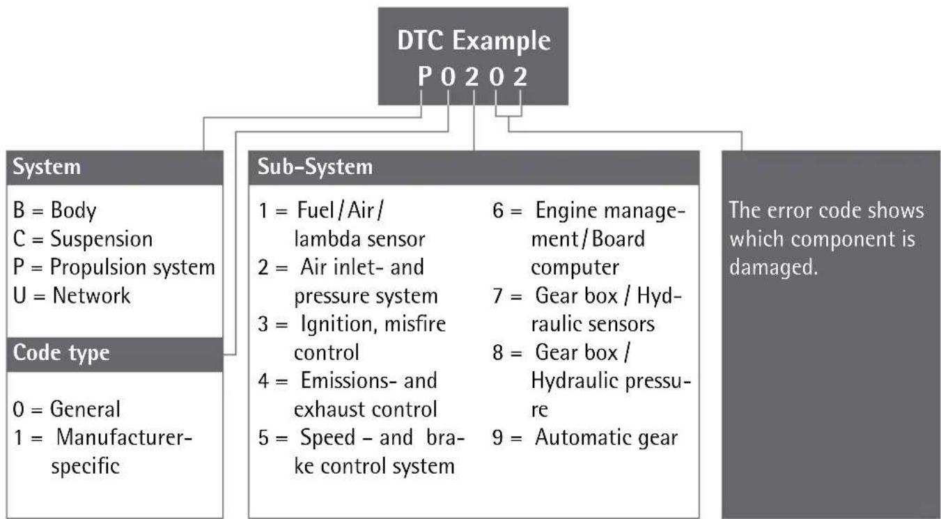
The different diagnosed codes identify a certain error on the vehicle. The diagnosed code / malfunction message consists of a 5 digit alphanumeric code. The first digit of the error code is a letter, which identifies the component of the vehicle. The remaining 4 digits will show a number, for example P0202.
These error codes help you to identify the main failure causes by means of the operator manual or the supplied software-CD. You will find additional information on the error code in the chapter "Vehicle diagnosed error," or in the Internet under OBD 2.
After unpacking immediately check the scope of delivery. Examine the device and all parts for damages. Do not take a defective device or part into operation.
Weight: approx. 250 g, incl.
Dimensions: approx.
WARNING! Read all safety guidelines and instructions. Omissions regarding the compliance to safety guidelines and instructions can cause electrical shock, fire and/or serious injuries. Keep all safety guidelines and instructions for future reference.
with the packing material. There is danger of suffocation.
This device is not intended for use by persons (including children) with reduced physical, sensory or mental abilities or lack of experience and/or lack of knowledge unless they are supervised by a person responsible for their security or received instructions from this person, how the equipment is to be used. Children should be supervised, in order to guarantee that they do not play with the device.
Liquid of any kind shall never penetrate the device. Mortal danger exists by electrical shock otherwise and danger of the damage.
- Do not let the device get into the hands of children and store it inaccessible for children. Small parts could be swallowed by children and lead to death by suffocation. Children could hurt themselves when using this device.
- Keep the device away from children. Children do not understand or recognise the possible dangers in handling electrical devices.
ATTENTION! DANGER TO LIFE AND DANGER OF INJURY, DANGER OF DAMAGE.
Secure the vehicle to prevent rolling before checking it with the OBD II Diagnostic Device OL 8000.
Always engage the hand-/parking brake and take care that it is not in gear during the check. An automatic gear box must be set to the „Park-Position“(P) and the hand-/parking brake must be engaged.
Take care that the device is always stored in a secure place. Do not expose the device to oils, grease, dampness, rain or wet ambient conditions. Avoid that water or other liquids run over the device or drip on it. Penetrating water causes an electrical short circuit and can damage the device or the vehicle.
Take care, that the device and the plugs are free of dampness. Never connect the device to the vehicle when hands are wet.
Do not expose the device to direct sun light.
- Route the connecting cable in such a way, that no one trips up and the cable gets damaged.
OL 8000 with the vehicle only when the ignition is turned off.
The deletion of error codes does not rectify the error on the vehicle. These error codes can be displayed again, until the damage is repaired by a garage. Let a specialised garage repair the malfunction on the vehicle.
The enclosed software CD covers most of the error codes displayed. You will receive information on more recent and some special error codes (mainly ^ ^ and ^ ) either via internet search engines (Search: 0BD2^ ) or from your specialised dealer
Check whether the vehicle has a 16-pole OBD II socket. Check the vehicle emission control label (VECI Label) to see if your vehicle can be diagnosed.
The OBD II socket is located in the area of the fuse box below the dashboard in most vehicles. Should you not find the OBD II-socket, please see the vehicle manual or ask your vehicle manufacturer.
The AEG OBD II diagnostic device OL 8000 works with all vehicles and small vans built as from 2000 with petrol engines and 2003 with diesel engines, which are equipped with OBD II-socket and contain the following diagnostic protocols: VPW, CAN, PWM, ISO 9141 and KWP2000.
The AEG OBD II diagnostic device OL 8000 reads and deletes general and manufacturer specific diagnosed error codes (DTC's) out of the engine control device
□ Vehicles built as from 2002 which are supported with the mode 9, the VIN (Vehicle Identification Number) of the vehicle is read out.
With this device, the status of the malfunction warning light (MIL) can be deleted. In addition the emission-display status can be monitored.
For this device a separate power supply is not required. The power supply and data transfer follows via the connection cable in combination with the on-board computer of the vehicle.
IMPORTANT NOTE! Switch of the vehicle before error diagnosis. The OBD II device must not be connected while the engine is still running or the ignition is still switched on.
Switch on the ignition again without starting the engine. In some vehicle types this ERROR message is not shown on the LC-display 1.
The AEG OBD II diagnostic device OL 8000 has 5 different menu-functions.
Press the button Taste LÖSCHEN/ERASE 2, to call up the separate menus in sequence;
A fast and direct deletion of all diagnosed error codes can also be carried out, without selection of the menu function.
To do this, press the button LÖSCHEN/ERASE 2 for at least 3 seconds and press the button LESEN/READ 3 afterwards.
The "I / M Readiness function" is an inspection program for checking the exhaust system of vehicles suitable for OBD II.
ATTENTION! Operate the OBD II diagnostic device OL 8000 only at standstill of the vehicle.
Note: Press the button LESEN / READ 3, to go back to the main menu.
After completion of the control program, the probable error codes are displayed.
The following errors or additional information can occur with the program 3.1M ..
YES All control programs, which the vehicle supports, have passed the separate diagnosis tests and the warning light MIL is off.
NO Not all control programs (at least 1) have completed the diagnosis test and / or the warning light is on.
READY Shows that a specific control program has carried out the respective diagnosis test.
NOT RDY (NOT READY) A specific control program has not carried out the diagnosis test.
N/A This control program is not supported by the vehicle.
Press the button LESEN/READ 3 to go back to the main menu.
With the menu function 4.VIN (Vehicle Identification Number) the chassis number of the vehicle can be called up. This is possible for vehicles built as from year 2002, which support the mode 9.
Note: A flashing arrow to the right indicates that more digits of the vehicle identification number can be called up. See these by pressing the button LÖSCHEN/ERASE 2. A flashing arrow to the left indicates that more digits of the vehicle identification number can be called up. See these by pressing the button LÖSCHEN/ERASE 2.
Press the button LESEN/READ 3, to go back to the main menu.
With the menu function »5.RESCAN« the main data stored in the control unit can be retrieved.
Furthermore, this menu function allows a new connection to the vehicle to be made.
The information to the separate error codes can be taken from this operating manual, from the chapter _error code list. The most important 1000 error codes are listed there.
The enclosed software-CD covers most of the error codes. You will receive information on more recent and some special error codes (mainly ^ "C" and U") either via internet search engines (Search: OBD 2") or from your specialised dealer.
Install the software on your PC or laptop. Follow the installation instructions of the software.
Windows 98, Processor min. 133 MHz
Windows ME, Processor min. 150 MHz
Windows 2000, Processor min. 133 MHz
Windows XP, Processor min. 300 MHz
Windows Vista, Processor min. 1 GHz
Windows 7
ATTENTION! The software on the enclosed CD is only compatible with the above mentioned operating systems.
The device is maintenance free.
WARNING! Before cleaning always separate the device from the power supply of the vehicle. To do this, pull out the OBD II connection plug 4.
Clean the device and the connection cable 4 regularly with a dry cloth. Never use solvents or other aggressive agents. Do not use any fluids to clean the device.
- Do not use hard brushes or metallic objects. If really dirty, clean the device with a slightly damp cloth. Always completely dry the device after cleaning
WARNING! Leave the repair of the device to qualified technical personnel to repair. Thus the safety of the device is guaranteed and maintained.
WARNING! Leave the exchange of the plug or the connecting cable always to qualified technical personnel. Thus the security of the equipment is guaranteed and maintained.
The general guarantee conditions refer to production and material defects. If the device is faulty, bring it to your specialist dealer respectively back to the sales office. In order to accelerate the warranty and repair work on the device, you need the following:
The packing consists of pollution free materials, which can dispose of you over the local recycling stations.
In accordance with European guideline 2002 / 96 / EC for electrical and old electronic devices and conversion to national law, used electrical appliances must be collected separately and brought to a environmental fair recycling.
For disposal possibilities for retired electrical appliances please inform yourself at your community or city administration.
| P0234 | Engine Overboost Condition |
| P0235 | Turbo/Super Boost Sensor A Circuit Malfunction |
| P0236 | Turbo/Super Boost Sensor ACKT Range/Performance |
| P0237 | Turbo/Super Boost Sensor A Circuit Low Input |
| P0238 | Turbo/Super Boost Sensor A Circuit High Input |
| P0239 | Turbo/Super Boost Sensor B Circuit Malfunction |
| P0240 | Turbo/Super Boost Sensor B CKT Range/Performance |
| P0241 | Turbo/Super Boost Sensor B Circuit Low Input |
| P0242 | Turbo/Super Boost Sensor B Circuit High Input |
| P0243 | Turbo/Sup Wastegate Solenoid A Malfunction |
| P0244 | Turbo/Sup Wastegate Solenoid A Range/Performance |
| P0245 | Turbo/Sup Wastegate Solenoid A Low |
| P0246 | Turbo/Sup Wastegate Solenoid A High |
| P0247 | Turbo/Sup Wastegate Solenoid B Malfunction |
| P0248 | Turbo/Sup Wastegate Solenoid B Range/Performance |
| P0249 | Turbo/Sup Wastegate Solenoid B Low |
| P0250 | Turbo/Sup Wastegate Solenoid B High |
| P0251 | Injection Pump Metering Control A |
| P0252 | Injection Pump Metering Control A Range/Performance |
| P0253 | Injection Pump Metering Control A Low |
| P0254 | Injection Pump Metering Control A High |
| P0255 | Injection Pump Metering Control A Intermittent (Cam/Rotor/Injector) |
| P0256 | Injection Pump Metering Control B Malfunction (Cam/Rotor/Injector) |
| P0257 | Injection Pump Metering Control B Range/Performance
(Cam/Rotor/Injector) |
| P0258 | Injection Pump Metering Control B Low (Cam/Rotor/Injector) |
| P0259 | Injection Pump Metering Control B High (Cam/Rotor/Injector) |
| P0260 | Injection Pump Metering Control B Intermittent (Cam/Rotor/Injector) |
| P0261 | Cylinder 1 Injector Control Circuit Low |
| P0262 | Cylinder 1 Injector Control Circuit High |
| P0263 | Cylinder 1 Contribution Balance Fault |
| P0264 | Cylinder 2 Injector Control Circuit Low |
| P0265 | Cylinder 2 Injector Control Circuit High |
| P0266 | Cylinder 2 Contribution Balance Fault |
| P0267 | Cylinder 3 Injector Control Circuit Low |
| P0268 | Cylinder 3 Injector Control Circuit High |
| P0269 | Cylinder 3 Contribution Balance Fault |
| P0270 | Cylinder 4 Injector Control Circuit Low |
| P0271 | Cylinder 4 Injector Control Circuit High |
| P0272 | Cylinder 4 Contribution Balance Fault |
| P0273 | Cylinder 5 Injector Control Circuit Low |
| P0274 | Cylinder 5 Injector Control Circuit High |
| P0275 | Cylinder 5 Contribution Balance Fault |
| P0276 | Cylinder 6 Injector Control Circuit Low |
| P0277 | Cylinder 6 Injector Control Circuit High |
| P0278 | Cylinder 6 Contribution Balance Fault |
| P0279 | Cylinder 7 Injector Control Circuit Low |
| P0280 | Cylinder 7 Injector Control Circuit High |
| P0281 | Cylinder 7 Contribution Balance Fault |
| P0282 | Cylinder 8 Injector Control Circuit Low |
| P0283 | Cylinder 8 Injector Control Circuit High |
| P0284 | Cylinder 8 Contribution Balance Fault |
| P0285 | Cylinder 9 Injector Control Circuit Low |
| P0286 | Cylinder 9 Injector Control Circuit High |
| P0287 | Cylinder 9 Contribution Balance Fault |
| P0288 | Cylinder 10 Injector Control Circuit Low |
| P0289 | Cylinder 10 Injector Control Circuit High |
| P0290 | Cylinder 10 Contribution Balance Fault |
| P0291 | Cylinder 11 Injector Control Circuit Low |
| P0292 | Cylinder 11 Injector Control Circuit High |
| P0293 | Cylinder 11 Contribution Balance Fault |
| P0294 | Cylinder 12 Injector Control Circuit Low |
| P0295 | Cylinder 12 Injector Control Circuit High |
| P0296 | Cylinder 12 Contribution Balance Fault |
| P0297 | Vehicle Overspeed Error |
| P0298 | Engine Oil Temperature Too High |
| P0299 | Turbo/Super Charger Underboost |
| P0300 | Random/Multiple Cylinder Misfire Detected |
| P0301 | Cylinder 1 Misfire Detected |
| P0302 | Cylinder 2 Misfire Detected |
| P0303 | Cylinder 3 Misfire Detected |
| P0304 | Cylinder 4 Misfire Detected |
| P0305 | Cylinder 5 Misfire Detected |
| P0306 | Cylinder 6 Misfire Detected |
| P0307 | Cylinder 7 Misfire Detected |
| P0308 | Cylinder 8 Misfire Detected |
| P0309 | Cylinder 9 Misfire Detected |
| P0310 | Cylinder 10 Misfire Detected |
| P0311 | Cylinder 11 Misfire Detected |
| P0312 | Cylinder 12 Misfire Detected |
| P0313 | Misfire Detected Low Fuel Level |
| P0314 | Misfire Detected Cyl. Not Specific |
| P0315 | Crankshaft Position System Variation Not Learned |
| P0316 | Misfire Detected 1st 1000 Revs. |
| P0317 | Rough Road Hardware Not Present |
| P0318 | Rough Road Sensor A Signal Circuit |
| P0319 | Rough Road Sensor B |
| P0320 | Ignition/Dist Engine Speed Input Circuit Malfunction |
| P0321 | Ignition/Dist Engine Speed Input CKT Range/Performance |
| P0322 | Ignition/Dist Engine Speed Input Circuit No Signal |
| P0323 | Ignition/Dist Engine Speed Input CKT Intermittent |
| P0324 | Knock Control System Malfunction |
| P0325 | Knock Sensor 1 Circuit Malfunction Bank 1 or 1 Sensor |
| P0326 | Knock Sensor 1 CKT Range/Performance Bank 1 or 1 Sensor |
| P0327 | Knock Sensor 1 Circuit Low Input Bank 1 or 1 Sensor |
| P0328 | Knock Sensor 1 Circuit High Input Bank 1 or 1 Sensor |
| P0329 | Knock Sensor 1 CKT Intermittent Bank 1 or 1 Sensor |
| P0330 | Knock Sensor 2 Circuit Malfunction (Bank 2) |
| P0331 | Knock Sensor 2 CKT Range/Performance (Bank 2) |
| P0332 | Knock Sensor 2 Circuit Low Input (Bank 2) |
| P0333 | Knock Sensor 2 Circuit High Input (Bank 2) |
| P0334 | Knock Sensor 2 CKT Intermittent (Bank 2) |
| P0335 | Crankshaft Position Sensor A Circuit Malfunction |
| P0336 | Crankshaft Position Sensor A CKT Range/Performance |
| P0337 | Crankshaft Position Sensor A Circuit Low Input |
| P0338 | Crankshaft Position Sensor A Circuit High Input |
| P0339 | Crankshaft Position Sensor A CKT Intermittent |
| P0340 | Camshaft Position Sensor A-Bank 1 Circuit Malfunction |
| P0341 | Camshaft Position Sensor A-Bank 1 CKT Range/Performance |
| P0342 | Camshaft Position Sensor A-Bank 1 Circuit Low Input |
| P0343 | Camshaft Position Sensor A-Bank 1 Circuit High Input |
| P0344 | Camshaft Position Sensor A-Bank 1 CKT Intermittent |
| P0345 | Camshaft Position Sensor A-Bank 2 Circuit Malfunction |
| P0346 | Camshaft Position Sensor A-Bank 2 CKT Range/Performance |
| P0347 | Camshaft Position Sensor A-Bank 2 Circuit Low Input |
| P0348 | Camshaft Position Sensor A-Bank 2 Circuit High Input |
| P0349 | Camshaft Position Sensor A-Bank 2 CKT Intermittent |
| P0350 | Ignition Coil Primary/Secondary Circuit Malfunction |
| P0351 | Ignition Coil A Primary/Secondary Circuit Malfunction |
| P0352 | Ignition Coil B Primary/Secondary Circuit Malfunction |
| P0353 | Ignition Coil C Primary/Secondary Circuit Malfunction |
| P0354 | Ignition Coil D Primary/Secondary Circuit Malfunction |
| P0355 | Ignition Coil E Primary/Secondary Circuit Malfunction |
| P0356 | Ignition Coil F Primary/Secondary Circuit Malfunction |
| P0357 | Ignition Coil G Primary/Secondary Circuit Malfunction |
| P0358 | Ignition Coil H Primary/Secondary Circuit Malfunction |
| P0359 | Ignition Coil I Primary/Secondary Circuit Malfunction |
| P0360 | Ignition Coil J Primary/Secondary Circuit Malfunction |
| P0361 | Ignition Coil K Primary/Secondary Circuit Malfunction |
| P0362 | Ignition Coil L Primary/Secondary Circuit Malfunction |
| P0363 | Misfire Detected Fueling Disabled |
| P0365 | Camshaft Position Sensor B-Bank 1 Circuit Malfunction |
| P0366 | Camshaft Position Sensor B-Bank 1 CKT Range/Performance |
| P0367 | Camshaft Position Sensor B-Bank 1 Circuit Low Input |
| P0368 | Camshaft Position Sensor B-Bank 1 Circuit High Input |
| P0369 | Camshaft Position Sensor B-Bank 1 CKT Intermittent |
| P0370 | Timing Reference High Resolution Signal A Malfunction |
| P0371 | Timing Reference High Resolution Signal A Too Many Pulses |
| P0372 | Timing Reference High Resolution Signal A Too Few Pulses |
| P0373 | Timing Reference High Resolution Signal A Erratic Pulses |
| P0374 | Timing Reference High Resolution Signal A No Pulses |
| P0375 | Timing Reference High Resolution Signal B Malfunction |
| P0376 | Timing Reference High Resolution Signal B Too Many Pulses |
| P0377 | Timing Reference High Resolution Signal B Too Few Pulses |
| P0378 | Timing Reference High Resolution Signal B Erratic Pulses |
| P0379 | Timing Reference High Resolution Signal B No Pulses |
| P0380 | Glow Plug/Heater CKT A Malfunction |
| P0381 | Glow Plug/Heater Indicator Circuit Malfunction |
| P0382 | Glow Plug/Heater CKT B Malfunction |
| P0383 | Glow Plug Module Control Circuit Low |
| P0384 | Glow Plug Module Control Circuit High |
| P0385 | Crankshaft Position Sensor B Circuit Malfunction |
| P0386 | Crankshaft Position Sensor B CKT Range/Performance |
| P0387 | Crankshaft Position Sensor B Circuit Low Input |
| P0388 | Crankshaft Position Sensor B Circuit High Input |
| P0389 | Crankshaft Position Sensor B CKT Intermittent |
| P0390 | Camshaft Position Sensor B-Bank 2 Circuit Malfunction |
| P0391 | Camshaft Position Sensor B-Bank 2 CKT Range/Performance |
| P0392 | Camshaft Position Sensor B-Bank 2 Circuit Low Input |
| P0393 | Camshaft Position Sensor B-Bank 2 Circuit High Input |
| P0394 | Camshaft Position Sensor B-Bank 2 CKT Intermittent |
| P0395 | DTC definitions not found! Please refer to vehicle service manual! |
| P0396 | DTC definitions not found! Please refer to vehicle service manual! |
| P0397 | DTC definitions not found! Please refer to vehicle service manual! |
| P0398 | DTC definitions not found! Please refer to vehicle service manual! |
| P0399 | DTC definitions not found! Please refer to vehicle service manual! |
| P0400 | EGR Flow Malfunction |
| P0401 | EGR Flow Insufficient |
| P0402 | EGR Flow Excessive |
| P0403 | EGR Flow Circuit Malfunction |
| P0404 | EGR Flow CKT Range/Performance |
| P0405 | EGR Flow Sensor A Circuit Low Input |
| P0406 | EGR Flow Sensor A Circuit High Input |
| P0407 | EGR Flow Sensor B Circuit Low Input |
| PO408 | EGR Flow Sensor B Circuit High Input |
| PO409 | EGR Flow Sensor A Circuit |
| PO410 | Secondary Air Injection System Malfunction |
| PO411 | Secondary Air Injection System Incorrect Flow |
| PO412 | Secondary Air Injection System Valve A Malfunction |
| PO413 | Secondary Air Injection System Valve A CKT Open |
| PO414 | Secondary Air Injection System Valve A CKT Short |
| PO415 | Secondary Air Injection System Valve B Malfunction |
| PO416 | Secondary Air Injection System Valve B CKT Open |
| PO417 | Secondary Air Injection System Valve B CKT Short |
| PO418 | Secondary Air Injection System Relay A Malfunction |
| PO419 | Secondary Air Injection System Relay B Malfunction |
| PO420 | Catalyst Efficiency Below Threshold(Bank 1) |
| PO421 | Warm Up Catalyst Below Threshold(Bank 1) |
| PO422 | Main Catalyst Below Threshold(Bank 1) |
| PO423 | Heated Catalyst Below Threshold(Bank 1) |
| PO424 | Heated Catalyst Temp Below Threshold(Bank 1) |
| PO425 | Catalyst Temp. Sensor (Bank 1 Sensor 1) |
| PO426 | Catalyst Temp. Sensor Performance(Bank 1 Sensor 1) |
| PO427 | Catalyst Temp. Sensor Circuit Low(Bank 1 Sensor 1) |
| PO428 | Catalyst Temp. Sensor Circuit High(Bank 1 Sensor 1) |
| PO429 | Catalyst Heater Control (Bank 1) |
| PO430 | Catalyst Efficiency Below Threshold (Bank 2) |
| PO431 | Warm Up Catalyst Below Threshold (Bank 2) |
| PO432 | Main Catalyst Below Threshold (Bank 2) |
| PO433 | Heated Catalyst Below Threshold (Bank 2) |
| PO434 | Heated Catalyst Temp Below Threshold (Bank 2) |
| PO435 | Catalyst Temp. Sensor (Bank 2 Sensor 1) |
| PO436 | Catalyst Temp. Sensor Performance (Bank 2 Sensor 1) |
| PO437 | Catalyst Temp. Sensor Circuit Low (Bank 2 Sensor 1) |
| PO438 | Catalyst Temp. Sensor Circuit High (Bank 2 Sensor 1) |
| PO439 | Catalyst Heater Control (Bank 2) |
| PO440 | EVAP Emission Control System Malfunction |
| PO441 | EVAP Emission Control System Purge Flow Fault |
| PO442 | EVAP Emission Control System Leak (Small) |
| PO443 | EVAP Emission Control System Purge Valve C Fault |
| PO444 | EVAP Emission Control System Purge Valve C Open |
| PO445 | EVAP Emission Control System Purge Valve C Short |
| PO446 | EVAP Emission Control System Vent Circuit Malf |
| PO447 | EVAP Emission Control System Vent Circuit Open |
| PO448 | EVAP Emission Control System Vent Circuit Short |
| PO449 | EVAP Emission Control System Vent Valve/Sol Malf |
| PO450 | EVAP Emission Control System Pres Sensor Fault |
| PO451 | EVAP Emission Control System Pres Sensor Range |
| PO452 | EVAP Emission Control System Pres Sensor Low |
| PO453 | EVAP Emission Control System Pres Sensor High |
| PO454 | EVAP Emission Control System Pres Sensor Erratic |
| PO455 | EVAP Emission Control System Leak (Large) |
| PO456 | EVAP Emission Control System Leak Very Small |
| PO457 | EVAP Emission Control System Leak Cap Loose/Off |
| PO458 | EVAP System Canister Purge Sol Circuit Low |
| PO459 | EVAP System Canister Purge Sol Circuit High |
| PO460 | Fuel Level Sensor A Circuit Malfunction |
| PO461 | Fuel Level Sensor A CKT Range/Performance |
| PO462 | Fuel Level Sensor A Circuit Low Input |
| PO463 | Fuel Level Sensor A Circuit High Input |
| PO464 | Fuel Level Sensor A CKT Intermittent |
| PO465 | EVAP Emission Purge Flow Sensor Circuit Malfunction |
| PO466 | EVAP Emission Purge Flow Sensor CKT Range/Performance |
| P0467 | EVAP Emission Purge Flow Sensor Circuit Low Input |
| P0468 | EVAP Emission Purge Flow Sensor Circuit High Input |
| P0469 | EVAP Emission Purge Flow Sensor Circuit Intermittent |
| P0470 | Exhaust Pressure Sensor Circuit Malfunction |
| P0471 | Exhaust Pressure Sensor CKT Range/Performance |
| P0472 | Exhaust Pressure Sensor Circuit Low Input |
| P0473 | Exhaust Pressure Sensor Circuit High Input |
| P0474 | Exhaust Pressure Sensor CKT Intermittent |
| P0475 | Exhaust Pressure Control Valve Circuit Malfunction |
| P0476 | Exhaust Pressure Control Valve CKT Range/Performance |
| P0477 | Exhaust Pressure Control Valve Circuit Low Input |
| P0478 | Exhaust Pressure Control Valve Circuit High Input |
| P0479 | Exhaust Pressure Control Valve CKT Intermittent |
| P0480 | Cooling Fan 1 Control Circuit |
| P0481 | Cooling Fan 2 Control Circuit |
| P0482 | Cooling Fan 3 Control Circuit |
| P0483 | Control Fan Rationality Check Malfunction |
| P0484 | Control Fan CKT Over Current |
| P0485 | Control Fan Power/Ground Circuit Malfunction |
| P0486 | EGR System Sensor B Circuit |
| P0487 | EGR TPS Control Circuit |
| P0488 | EGR TPS Control CKT Range/Performance |
| P0489 | EGR Control Circuit Low |
| P0490 | EGR Control Circuit High |
| P0491 | Secondary Air System (Bank 1) |
| P0492 | Secondary Air System (Bank 2) |
| P0493 | Fan Speed Overspeed |
| P0494 | Fan Speed Low |
| P0495 | Fan Speed High |
| P0496 | EVAP Emission High Purge Flow Fault |
| P0497 | EVAP Emission Low Purge Flow Fault |
| P0498 | EVAP Emission Vent VIV/Sol Malf Circuit Low |
| P0499 | EVAP Emission Vent VIV/Sol Malf Circuit High |
| P0500 | Vehicle Speed Sensor A Malfunction |
| P0501 | Vehicle Speed Sensor A Range/Performance |
| P0502 | Vehicle Speed Sensor A Circuit Low Input |
| P0503 | Vehicle Speed Sensor A Erratic/High |
| P0504 | Brake Switch A Brake Switch B Correlation |
| P0505 | Idle Control System Malfunction |
| P0506 | Idle Control System RPM Low |
| P0507 | Idle Control System RPM High |
| P0508 | Idle Control System Circuit Low |
| P0509 | Idle Control System Circuit High |
| P0510 | Closed Throttle Position Switch |
| P0511 | Idle Air Control Circuit |
| P0512 | Starter Signal Circuit |
| P0513 | Immobilizer Incorrect |
| P0514 | Battery Temperature Sensor CKT Range/Performance |
| P0515 | Battery Temperature Sensor Circuit |
| P0516 | Battery Temperature Circuit Low |
| P0517 | Battery Temperature Circuit High |
| P0518 | Idle Air Control CKT Intermittent |
| P0519 | Idle Air Control System Performance |
| P0520 | Engine Oil Pressure Sensor/Switch Circuit Malfunction |
| P0521 | Engine Oil Pressure Sensor/Switch Range/Performance |
| P0522 | Engine Oil Pressure Sensor/Switch Low Voltage |
| P0523 | Engine Oil Pressure Sensor/Switch High Voltage |
| P0524 | Engine Oil Pressure Too Low |
| P0525 | Cruise Servo CKT Range/Performance |
| P0526 | Fan Speed Sensor Circuit |
| P0527 | Fan Speed Sensor CKT Range/Performance |
| P0528 | Fan Speed Sensor Circuit No Signal |
| P0529 | Fan Speed Sensor CKT Intermittent |
| P0530 | A/C Refrigerant Pressure Sensor A Circuit Malfunction |
| P0531 | A/C Refrigerant Pressure Sensor A CKT Range/Performance |
| P0532 | A/C Refrigerant Pressure Sensor A Circuit Low Input |
| P0533 | A/C Refrigerant Pressure Sensor A Circuit High Input |
| P0534 | A/C Refrigerant Charge Loss |
| P0535 | A/C Evaporator Temperature Sensor Circuit |
| P0536 | A/C Evaporator Temperature Sensor CKT Range/Performance |
| P0537 | A/C Evaporator Temperature Sensor Circuit Low |
| P0538 | A/C Evaporator Temperature Sensor Circuit High |
| P0539 | A/C Evaporator Temperature Sensor CKT Intermittent |
| P0540 | Intake Air Heater A Circuit |
| P0541 | Intake Air Heater A Circuit Low |
| P0542 | Intake Air Heater A Circuit High |
| P0543 | Intake Air Heater A Circuit Open |
| P0544 | Exhaust Gas Temp. Sensor Circuit (Bank 1 Sensor 1) |
| P0545 | Exhaust Gas Temp. Sensor Circuit Low (Bank 1 Sensor 1) |
| P0546 | Exhaust Gas Temp. Sensor Circuit High (Bank 1 Sensor 1) |
| P0547 | Exhaust Gas Temp. Sensor Circuit (Bank 2 Sensor 1) |
| P0548 | Exhaust Gas Temp. Sensor Circuit Low (Bank 2 Sensor 1) |
| P0549 | Exhaust Gas Temp. Sensor Circuit High (Bank 2 Sensor 1) |
| P0550 | Power Steering Pres Sensor Circuit Malfunction |
| P0551 | Power Steering Pres Sensor CKT Range/Performance |
| P0552 | Power Steering Pres Sensor Circuit Low Input |
| P0553 | Power Steering Pres Sensor Circuit High Input |
| P0554 | Power Steering Pres Sensor CKT Intermittent |
| P0555 | Brake Booster Pressure Sensor Circuit |
| P0556 | Brake Booster Pressure Sensor CKT Range/Performance |
| P0557 | Brake Booster Pressure Sensor Circuit Low Input |
| P0558 | Brake Booster Pressure Sensor Circuit High Input |
| P0559 | Brake Booster Pressure Sensor CKT Intermittent |
| P0560 | System Voltage Malfunction |
| P0561 | System Voltage Unstable |
| P0562 | System Voltage Low |
| P0563 | System Voltage High |
| P0564 | Cruise Control Multi-Function, Input A Signal Error |
| P0565 | Cruise Control On Signal Malfunction |
| P0566 | Cruise Control Off Signal Malfunction |
| P0567 | Cruise Control Resume Signal Malfunction |
| P0568 | Cruise Control Set Signal Malfunction |
| P0569 | Cruise Control Coast Signal Malfunction |
| P0570 | Cruise Control Acceleration Signal Malfunction |
| P0571 | Brake Switch A Circuit Malfunction |
| P0572 | Brake Switch A Circuit Low Input |
| P0573 | Brake Switch A Circuit High Input |
| P0574 | Cruise Control Vehicle Speed Too High |
| P0575 | Cruise Control Circuit Malfunction |
| P0576 | Cruise Control Circuit Low Input |
| P0577 | Cruise Control Circuit High Input |
| P0578 | Cruise Control Multi-Function Input A Circuit Stuck |
| P0579 | Cruise Control Multi-Function Input A CKT Range/Performance |
| P0580 | Cruise Control Multi-Function Input A Circuit Low |
| P0581 | Cruise Control Multi-Function Input A Circuit High |
| P0582 | Cruise Control Vacuum Control Circuit Open |
| P0583 | Cruise Control Vacuum Control Circuit Low |
| P0584 | Cruise Control Vacuum Control Circuit High |
| P0585 | Cruise Control Multi-Function Input Correlation |
| P0586 | Cruise Control Vent Control Circuit Open |
| P0587 | Cruise Control Vent Control Circuit Low |
| P0588 | Cruise Control Vent Control Circuit High |
| P0589 | Cruise Control Multi-Function Input B Circuit |
| P0590 | Cruise Control Multi-Function Input B Circuit Stuck |
| P0591 | Cruise Control Multi-Function Input B CKT Range/Performance |
| P0592 | Cruise Control Multi-Function Input B Circuit Low |
| P0593 | Cruise Control Multi-Function Input B Circuit High |
| P0594 | Cruise Control Servo Control Circuit Open |
| P0595 | Cruise Control Servo Control Circuit Low |
| P0596 | Cruise Control Servo Control Circuit High |
| P0597 | Cruise Control Circuit Open |
| P0598 | Cruise Control Circuit Low |
| P0599 | Cruise Control Circuit High |
| P0600 | Serial Communication Link Malfunction |
| P0601 | Internal Control Module Memory Check Sum Error |
| P0602 | Control Module Programming Error |
| P0603 | PCM Keep Alive Memory (KAM) Error |
| P0604 | PCM Random Access Memory (RAM) Error |
| P0605 | PCM Read Only Memory (ROM) Error |
| P0606 | PCM Processor Fault |
| P0607 | Control Module Performance |
| P0608 | Control Module VSS Output A Malfunction |
| P0609 | Control Module VSS Output B Malfunction |
| P0610 | Control Module Vehicle Options Malfunction |
| P0611 | Injector Control Module Performance |
| P0612 | Injector Control Module Relay Control |
| P0613 | TCM Processor Fault |
| P0614 | ECM/TCM Incompatible |
| P0615 | Starter Relay Circuit |
| P0616 | Starter Relay Circuit Low |
| P0617 | Starter Relay Circuit High |
| P0618 | Alternative Fuel Module (KAM) Error |
| P0619 | Alternative Fuel Module Memory |
| P0620 | Generator Control Malfunction |
| P0621 | Generator L-Term. Lamp Control |
| P0622 | Generator L-Term. Field F Control |
| P0623 | Generator Lamp Control Circuit |
| P0624 | Fuel Cap Lamp Circuit |
| P0625 | Generator F-Term. Circuit Low |
| P0626 | Generator F-Term. Circuit High |
| P0627 | Fuel Pump A Control Circuit Open |
| P0628 | Fuel Pump A Control Circuit Low |
| P0629 | Fuel Pump A Control Circuit High |
| P0630 | PCM VIN Not Program, Or Mismatch |
| P0631 | TCM VIN Not Program, Or Mismatch |
| P0632 | Odometer Code Not Programmed ECM/PCM |
| P0633 | Immobilizer Code Not Programmed ECM/PCM |
| P0634 | PCM/ECM/TCM Internal Temp, Too High |
| P0635 | Power Steering Control Circuit |
| P0636 | Power Steering Control Circuit Low |
| P0637 | Power Steering Control Circuit High |
| P0638 | Throttle Actuator Range/Performance (Bank 1) |
| P0639 | Throttle Actuator Range/Performance (Bank 2) |
| P0640 | Intake Air Heater Control Circuit |
| P0641 | Sensor A Reference Voltage Circuit Open |
| P0642 | Sensor A Reference Voltage Circuit Low |
| P0643 | Sensor A Reference Voltage Circuit High |
| P0644 | Driver Display Serial Communication Link |
| P0645 | A/C Clutch Relay Control Circuit |
| P0646 | A/C Clutch Relay Control Circuit Low |
| P0647 | A/C Clutch Relay Control Circuit High |
| P0648 | Immobilizer Lamp Circuit |
| P0649 | Cruise Control Lamp Circuit |
| P0650 | MIL Control Circuit Malfunction |
| P0651 | Sensor B Reference Voltage Circuit Open |
| P0652 | Sensor B Reference Voltage Circuit Low |
| P0653 | Sensor B Reference Voltage Circuit High |
| P0654 | Engine RPM Circuit Malfunction |
| P0655 | Engine Hot Lamp Output Circuit Malfunction |
| P0656 | Fuel Level Output Circuit Malfunction |
| P0657 | Actuator Supply Voltage A Circuit Open |
| P0658 | Actuator Supply Voltage A Circuit Low |
| P0659 | Actuator Supply Voltage A Circuit High |
| P0660 | Intake Man Tuning Control CKT Open (Bank 1) |
| P0661 | Intake Man Tuning Control CKT Low (Bank 1) |
| P0662 | Intake Man Tuning Control CKT High (Bank 1) |
| P0663 | Intake Man Tuning Control CKT Open (Bank 2) |
| P0664 | Intake Man Tuning Control CKT Low (Bank 2) |
| P0665 | Intake Man Tuning Control CKT High (Bank 2) |
| P0666 | PCM/ECM/TCM Internal Temp. Sensor Circuit |
| P0667 | PCM/ECM/TCM Internal Temp. Sensor Range/Performance |
| P0668 | PCM/ECM/TCM Internal Temp. Sensor Circuit Low |
| P0669 | PCM/ECM/TCM Internal Temp. Sensor Circuit High |
| P0670 | Glow Plug/Heater Module Control |
| P0671 | Glow Plug/Heater Cylinder 1 |
| P0672 | Glow Plug/Heater Cylinder 2 |
| P0673 | Glow Plug/Heater Cylinder 3 |
| P0674 | Glow Plug/Heater Cylinder 4 |
| P0675 | Glow Plug/Heater Cylinder 5 |
| P0676 | Glow Plug/Heater Cylinder 6 |
| P0677 | Glow Plug/Heater Cylinder 7 |
| P0678 | Glow Plug/Heater Cylinder 8 |
| P0679 | Glow Plug/Heater Cylinder 9 |
| P0680 | Glow Plug/Heater Cylinder 10 |
| P0681 | Glow Plug/Heater Cylinder 11 |
| P0682 | Glow Plug/Heater Cylinder 12 |
| P0683 | Glow Plug/Heater Module Communication Problem |
| P0684 | Glow Plug/Heater Communication Problem CKT Range/Performance |
| P0685 | ECM/PCM Power Relay Control Circuit Open |
| P0686 | ECM/PCM Power Relay Control Circuit Low |
| P0687 | ECM/PCM Power Relay Control Circuit High |
| P0688 | ECM/PCM Power Relay Sense Circuit Open |
| P0689 | ECM/PCM Power Relay Sense Circuit Low |
| P0690 | ECM/PCM Power Relay Sense Circuit High |
| P0691 | Fan 1 Control Circuit Low |
| P0692 | Fan 1 Control Circuit High |
| P0693 | Fan 2 Control Circuit Low |
| P0694 | Fan 2 Control Circuit High |
| P0695 | Fan 3 Control Circuit Low |
| P0696 | Fan 3 Control Circuit High |
| P0697 | Sensor C Reference Voltage Circuit Open |
| P0698 | Sensor C Reference Voltage Circuit Low |
| P0699 | Sensor C Reference Voltage Circuit High |
| P0700 | Trans Control System Malfunction |
| P0701 | Trans Control System Range/Performance |
| P0702 | Trans Control System Electrical |
| P0703 | Brake Switch B Circuit Malfunction |
| P0704 | Clutch Switch Input Circuit Malfunction |
| P0705 | Trans Range Sensor Circuit Malfunction (PRNDL Input) |
| P0706 | Trans Range Sensor CKT Range/Performance |
| P0707 | Trans Range Sensor Circuit Low Input |
| P0708 | Trans Range Sensor Circuit High Input |
| P0709 | Trans Range Sensor CKT Intermittent |
| P0710 | Transmission Fluid Temperature Sensor Circuit Malfunction |
| P0711 | Trans Fluid Temp Sensor A CKT Range/Performance |
| P0712 | Trans Fluid Temp Sensor A Circuit Low Input |
| P0713 | Trans Fluid Temp Sensor A Circuit High Input |
| P0714 | Trans Fluid Temp Sensor A CKT Intermittent |
| P0715 | Input/Turbine Speed Sensor A Circuit Malfunction |
| P0716 | Input/Turbine Speed Sensor A CKT Range/Performance |
| P0717 | Input/Turbine Speed Sensor A Circuit No Signal |
| P0718 | Input/Turbine Speed Sensor A CKT Intermittent |
| P0719 | Brake Switch B Circuit Low Input |
| P0720 | Output Speed Sensor Circuit Malfunction |
| P0721 | Output Speed Sensor CKT Range/Performance |
| P0722 | Output Speed Sensor Circuit No Signal |
| P0723 | Output Speed Sensor CKT Intermittent |
| P0724 | Brake Switch B Circuit High Input |
| P0725 | Engine Speed Sensor Circuit Malfunction |
| P0726 | Engine Speed Sensor CKT Range/Performance |
| P0727 | Engine Speed Sensor Circuit No Signal |
| P0728 | Engine Speed Sensor CKT Intermittent |
| P0729 | Gear 6 Ratio Incorrect |
| P0730 | Gear Ratio Incorrect |
| P0731 | Gear 1 Ratio Incorrect |
| P0732 | Gear 2 Ratio Incorrect |
| P0733 | Gear 3 Ratio Incorrect |
| P0734 | Gear 4 Ratio Incorrect |
| P0735 | Gear 5 Ratio Incorrect |
| P0736 | Reverse Ratio Incorrect |
| P0737 | TCM Engine Speed Output Circuit |
| P0738 | TCM Engine Speed Output Circuit Low |
| P0739 | TCM Engine Speed Output Circuit High |
| P0740 | TCC Circuit Malfunction |
| P0741 | Torque Converter CKT Performance Or Stuck Off |
| P0742 | Torque Converter Circuit Stuck On |
| P0743 | Torque Converter Circuit Electrical |
| P0744 | Torque Converter CKT Intermittent |
| P0745 | Pres Control Sol. A Circuit Malfunction |
| P0746 | Pres Control Sol. A CKT Performance Or Stuck Off |
| P0747 | Pres Control Sol. A Circuit Stuck On |
| P0748 | Pres Control Sol. A Circuit Electrical |
| P0749 | Pres Control Sol. A CKT Intermittent |
| P0750 | Shift Solenoid A Malfunction |
| P0751 | Shift Solenoid A CKT Performance Or Stuck Off |
| P0752 | Shift Solenoid A Circuit Stuck On |
| P0753 | Shift Solenoid A Circuit Electrical |
| P0754 | Shift Solenoid A CKT Intermittent |
| P0755 | Shift Solenoid B Malfunction |
| P0756 | Shift Solenoid B CKT Performance Or Stuck Off |
| P0757 | Shift Solenoid B Circuit Stuck On |
| P0758 | Shift Solenoid B Circuit Electrical |
| P0759 | Shift Solenoid B CKT Intermittent |
| P0760 | Shift Solenoid C Malfunction |
| P0761 | Shift Solenoid C CKT Performance Or Stuck Off |
| P0762 | Shift Solenoid C Circuit Stuck On |
| P0763 | Shift Solenoid C Circuit Electrical |
| P0764 | Shift Solenoid C CKT Intermittent |
| P0765 | Shift Solenoid D Malfunction |
| P0766 | Shift Solenoid D CKT Performance Or Stuck Off |
| P0767 | Shift Solenoid D Circuit Stuck On |
| P0768 | Shift Solenoid D Circuit Electrical |
| P0769 | Shift Solenoid D CKT Intermittent |
| P0770 | Shift Solenoid E Malfunction |
| P0771 | Shift Solenoid E CKT Performance Or Stuck Off |
| P0772 | Shift Solenoid E Circuit Stuck On |
| P0773 | Shift Solenoid E Circuit Electrical |
| P0774 | Shift Solenoid E CKT Intermittent |
| P0775 | Pres Ctrl Sol. B Circuit Malfunction |
| P0776 | Pres Ctrl Sol. B CKT Performance Or Stuck Off |
| P0777 | Pres Ctrl Sol. B Circuit Stuck On |
| P0778 | Pres Ctrl Sol. B Circuit Electrical |
| P0779 | Pres Ctrl Sol. B CKT Intermittent |
| P0780 | Shift Malfunction |
| P0781 | 1-2 Shift Malfunction |
| P0782 | 2-3 Shift Malfunction |
| P0783 | 3-4 Shift Malfunction |
| P0784 | 4-5 Shift Malfunction |
| P0785 | Shift/Timing Solenoid Malfunction |
| P0786 | Shift/Timing Solenoid Range/Performance |
| P0787 | Shift/Timing Solenoid Low |
| P0788 | Shift/Timing Solenoid High |
| P0789 | Shift/Timing Solenoid Intermittent CKT |
| P0790 | Normal/performance Switch Circuit Malfunction |
| P0791 | Intermediate Shaft Speed Sensor A Circuit |
| P0792 | Intermediate Shaft Speed Sensor A Circuit Range/Performance |
| P0793 | Intermediate Shaft Speed Sensor A Circuit No Signal |
| P0794 | Intermediate Shaft Speed Sensor A CKT Intermittent |
| P0795 | Pres Ctrl Sol. C Malfunction |
| P0796 | Pres Ctrl Sol. C CKT Performance Or Stuck Off |
| P0797 | Pres Ctrl Sol. C Circuit Stuck On |
| P0798 | Pres Ctrl Sol. C Circuit Electrical |
| P0799 | Pres Ctrl Sol. C CKT Intermittent |
| P0800 | Transfer Case Control System MIL Request |
| P0801 | Reverse Inhibit Control Circuit Malfunction |
| P0802 | Trans Control Sys MIL Request Circuit Open |
| P0803 | 1-4 Upshift (Skip Shift) Solenoid Circuit Malfunction |
| P0804 | 1-4 Upshift (Skip Shift) Lamp Circuit Malfunction |
| P0805 | Clutch Position Sensor Circuit Malfunction |
| P0806 | Clutch Position Sensor Circuit Range/Performance |
| P0807 | Clutch Position Sensor Circuit Low |
| P0808 | Clutch Position Sensor Circuit High |
| P0809 | Clutch Position Sensor Circuit Intermittent CKT |
| P0810 | Clutch Position Control Malfunction |
| P0811 | Clutch Slippage Excessive |
| P0812 | Reverse Input Circuit Malfunction |
| P0813 | Reverse Output Circuit Malfunction |
| P0814 | Trans Range Display Circuit Malfunction |
| P0815 | Upshift Switch Circuit Malfunction |
| P0816 | Downshift Switch Circuit Malfunction |
| P0817 | Starter Disable Circuit |
| P0818 | Driveline Disconnect. Switch Input |
| P0819 | Up/Down Shift SW Transmission Range Correlation |
| P0820 | Gear Lever X-Y Sensor Circuit |
| P0821 | Gear Lever X Sensor Circuit |
| P0822 | Gear Lever Y Sensor Circuit |
| P0823 | Gear Lever X Sensor Circuit Intermittent Ckt |
| P0824 | Gear Lever Y Sensor Circuit Intermittent Ckt |
| P0825 | Gear Lever Push/Pull Switch (Shift Anticipate) |
| P0826 | Upshift Switch Downshift Switch Circuit |
| P0827 | Upshift Switch Downshift Switch Circuit Low |
| P0828 | Upshift Switch Downshift Switch Circuit High |
| P0829 | 5-6 Shift |
| P0830 | Clutch Position Switch A Circuit Malfunction |
| P0831 | Clutch Position Switch A Circuit Low |
| P0832 | Clutch Position Switch A Circuit High |
| P0833 | Clutch Position Switch B Circuit Malfunction |
| P0834 | Clutch Position Switch B Circuit Low |
| P0835 | Clutch Position Switch B Circuit High |
| P0836 | 4 Wheel Drive Switch Circuit Malfunction |
| P0837 | 4 Wheel Drive Switch CKT Range/Performance |
| P0838 | 4 Wheel Drive Switch Circuit Low |
| P0839 | 4 Wheel Drive Switch Circuit High |
| P0840 | Trans Fluid Press Sensor/Switch A Circuit Malfunction |
| P0841 | Trans Fluid Press Sensor/Switch A CKT Range/Performance |
| P0842 | Trans Fluid Press Sensor/Switch A Circuit Low |
| P0843 | Trans Fluid Press Sensor/Switch A Circuit High |
| P0844 | Trans Fluid Press Sensor/Switch A CKT Intermittent |
| P0845 | Trans Fluid Press Sensor/Switch B Circuit Malfunction |
| P0846 | Trans Fluid Press Sensor/Switch B CKT Range/Performance |
| P0847 | Trans Fluid Press Sensor/Switch B Circuit Low |
| P0848 | Trans Fluid Press Sensor/Switch B Circuit High |
| P0849 | Trans Fluid Press Sensor/Switch B CKT Intermittent |
| P0850 | Park/Neutral Switch Input Circuit |
| P0851 | Park/Neutral Switch Circuit Low Input |
| P0852 | Park/Neutral Switch Circuit High Input |
| P0853 | Drive Switch Input Circuit |
| P0854 | Drive Switch Circuit Low Input |
| P0855 | Drive Switch Circuit High Input |
| P0856 | Traction Control Input Signal |
| P0857 | Traction Control Input Signal Range/Performance |
| P0858 | Traction Control Input Signal Low |
| P0859 | Traction Control Input Signal High |
| P0860 | Gear Shift Module Communications Circuit |
| P0861 | Gear Shift Module Communications Circuit Low |
| P0862 | Gear Shift Module Communications Circuit High |
| P0863 | TCM Communications Circuit |
| P0864 | TCM Communications CKT Range/Performance |
| P0865 | TCM Communications Circuit Low |
| P0866 | TCM Communications Circuit High |
| P0867 | Trans Fluid Press |
| P0868 | Trans Fluid Press Low |
| P0869 | Trans Fluid Press High |
| P0870 | Trans Fluid Press Sensor/Switch C Circuit |
| P0871 | Trans Fluid Press Sensor/Switch C CKT Range/Performance |
| P0872 | Trans Fluid Press Sensor/Switch C Circuit Low |
| P0873 | Trans Fluid Press Sensor/Switch C Circuit High |
| P0874 | Trans Fluid Press Sensor/Switch C CKT Intermittent |
| P0875 | Trans Fluid Press Sensor/Switch D Circuit |
| P0876 | Trans Fluid Press Sensor/Switch D CKT Range/Performance |
| P0877 | Trans Fluid Press Sensor/Switch D Circuit Low |
| P0878 | Trans Fluid Press Sensor/Switch D Circuit High |
| P0879 | Trans Fluid Press Sensor/Switch D CKT Intermittent |
| P0880 | TCM Power Input Signal |
| P0881 | TCM Power Input Signal Range/Performance |
| P0882 | TCM Power Input Signal Low |
| P0883 | TCM Power Input Signal High |
| P0884 | TCM Power Input Signal CKT Intermittent |
| P0885 | TCM Power Relay Control Circuit Open |
| P0886 | TCM Power Relay Control Circuit Low |
| P0887 | TCM Power Relay Control Circuit High |
| P0888 | TCM Power Relay Sense Circuit |
| P0889 | TCM Power Relay Sense CKT Range/Performance |
| P0890 | TCM Power Relay Sense Circuit Low |
| P0891 | TCM Power Relay Sense Circuit High |
| P0892 | TCM Power Relay Sense CKT Intermittent |
| P0893 | Multiple Gears Engaged |
| P0894 | Transmission Comp. Slipping |
| P0895 | Shift Time Too Short |
| P0896 | Shift Time Too Long |
| P0897 | Transmission Fluid Deteriorated |
| P0898 | Transmission Ctrl.MIL Request Circuit Low |
| P0899 | Transmission Ctrl.MIL Request Circuit High |
| P0900 | Clutch Actuator Circuit Open |
| P0901 | Clutch Actuator CKT Range/Performance |
| P0902 | Clutch Actuator Circuit Low |
| P0903 | Clutch Actuator Circuit High |
| P0904 | Gate Select Position Circuit |
| P0905 | Gate Select Position CKT Range/Performance |
| P0906 | Gate Select Position Circuit Low |
| P0907 | Gate Select Position Circuit High |
| P0908 | Gate Select Position CKT Intermittent |
| P0909 | Gate Select Control Error |
| P0910 | Gate Select Actuator Circuit Open |
| P0911 | Gate Select Actuator CKT Range/Performance |
| P0912 | Gate Select Actuator Circuit Low |
| P0913 | Gate Select Actuator Circuit High |
| P0914 | Gear Shift Position Circuit |
| P0915 | Gear Shift Position CKT Range/Performance |
| P0916 | Gear Shift Position Circuit Low |
| P0917 | Gear Shift Position Circuit High |
| P0918 | Gear Shift Position CKT Intermittent |
| P0919 | Gear Shift Position Control Error |
| P0920 | Gear Shift Forward Actuator Circuit Open |
| P0921 | Gear Shift Forward Actuator CKT Range/Performance |
| P0922 | Gear Shift Forward Actuator Circuit Low |
| P0923 | Gear Shift Forward Actuator Circuit High |
| P0924 | Gear Shift Reverse Actuator Circuit Open |
| P0925 | Gear Shift Reverse Actuator CKT Range/Performance |
| P0926 | Gear Shift Reverse Actuator Circuit Low |
| P0927 | Gear Shift Reverse Actuator Circuit High |
| P0928 | Gear Shift Lock Solenoid Ctrl Circuit Open |
| P0929 | Gear Shift Lock Solenoid Ctrl CKT Range/Performance |
| P0930 | Gear Shift Lock Solenoid Ctrl Circuit Low |
| P0931 | Gear Shift Lock Solenoid Ctrl Circuit High |
| P0932 | Hydraulic Pressure Sensor Circuit |
| P0933 | Hydraulic Pressure Sensor CKT Range/Performance |
| P0934 | Hydraulic Pressure Sensor Circuit Low |
| P0935 | Hydraulic Pressure Sensor Circuit High |
| P0936 | Hydraulic Pressure Sensor CKT Intermittent |
| P0937 | Hydraulic Oil Temp Sensor Circuit |
| P0938 | Hydraulic Oil Temp Sensor CKT Range/Performance |
| P0939 | Hydraulic Oil Temp Sensor Circuit Low |
| P0940 | Hydraulic Oil Temp Sensor Circuit High |
| P0941 | Hydraulic Oil Temp Sensor CKT Intermittent |
| P0942 | Hydraulic Pressure Unit |
| P0943 | Hyd. Pressure Unit Cycling Too Short |
| P0944 | Hyd. Pressure Unit Loss of Pressure |
| P0945 | Hyd. Pump Relay Circuit Open |
| P0946 | Hyd. Pump Relay CKT Range/Performance |
| P0947 | Hyd. Pump Relay Circuit Low |
| P0948 | Hyd. Pump Relay Circuit High |
| P0949 | Auto Shift Adaptive Learning Not Complete |
| P0950 | Auto Shift Manual Control Circuit |
| P0951 | Auto Shift Manual Control CKT Range/Performance |
| P0952 | Auto Shift Manual Control Circuit Low |
| P0953 | Auto Shift Manual Control Circuit High |
| P0954 | Auto Shift Manual Control CKT Intermittent |
| P0955 | Auto Shift Manual Mode Circuit |
| P0956 | Auto Shift Manual Mode CKT Range/Performance |
| P0957 | Auto Shift Manual Mode Circuit Low |
| P0958 | Auto Shift Manual Mode Circuit High |
| P0959 | Auto Shift Manual Mode CKT Intermittent |
| P0960 | Pressure Control Solenoid A Control Circuit Open |
| P0961 | Pressure Control Solenoid A Control CKT Range/Performance |
| P0962 | Pressure Control Solenoid A Control Circuit Low |
| P0963 | Pressure Control Solenoid A Control Circuit High |
| P0964 | Pressure Control Solenoid B Control Circuit Open |
| P0965 | Pressure Control Solenoid B Control CKT Range/Performance |
| P0966 | Pressure Control Solenoid B Control Circuit Low |
| P0967 | Pressure Control Solenoid B Control Circuit High |
| P0968 | Pressure Control Solenoid C Control Circuit Open |
| P0969 | Pressure Control Solenoid C Control CKT Range/Performance |
| P0970 | Pressure Control Solenoid C Control Circuit Low |
| P0971 | Pressure Control Solenoid C Control Circuit High |
| P0972 | Shift Solenoid A Control CKT Range/Performance |
| P0973 | Shift Solenoid A Control Circuit Low |
| P0974 | Shift Solenoid A Control Circuit High |
| P0975 | Shift Solenoid B Control CKT Range/Performance |
| P0976 | Shift Solenoid B Control Circuit Low |
| P0977 | Shift Solenoid B Control Circuit High |
| P0978 | Shift Solenoid C Control CKT Range/Performance |
| P0979 | Shift Solenoid C Control Circuit Low |
| P0980 | Shift Solenoid C Control Circuit High |
| P0981 | Shift Solenoid D Control CKT Range/Performance |
| P0982 | Shift Solenoid D Control Circuit Low |
| P0983 | Shift Solenoid D Control Circuit High |
| P0984 | Shift Solenoid E Control CKT Range/Performance |
| P0985 | Shift Solenoid E Control Circuit Low |
| P0986 | Shift Solenoid E Control Circuit High |
| P0987 | Trans Fluid Press Sensor/Switch E Circuit |
| P0988 | Trans Fluid Press Sensor/Switch E CKT Range/Performance |
| P0989 | Trans Fluid Press Sensor/Switch E Circuit Low |
P0994 Trans Fluid Press Sensor/Switch F Circuit LowP0995 Trans Fluid Press Sensor/Switch F Circuit High
Illustrations may vary slightly from the product itself. We reserve the right to administer changes due to technical progress. Decoration not included.
Dimensions: env. 13,8 × 9,0 ×
www.aeg-automotive.com AEG is a registered trademark used under license from AB Electrolux (publ)