PA8120RCD - Receiver Monacor - Free user manual and instructions
Find the device manual for free PA8120RCD Monacor in PDF.
| Product Type | Public Address mixer amplifier with radio and CD/MP3 player |
| Brand | Monacor |
| Model | PA8120RCD |
| Rated power | 120 W RMS |
| Speaker outputs | 4/8/16 Ω (low impedance) and 70/100 V (line) |
| Microphone inputs | 4 inputs (XLR/6.35 mm balanced jack) with 48 V phantom power |
| Line inputs | 2 stereo AUX inputs (RCA and screw terminals) |
| Built-in radio | FM (87.5-108 MHz) and AM (525-1650 kHz) with 5 presets each |
| CD/MP3 player | Audio CD, CD-R, CD-RW, MP3 files; front USB port |
| Equalizer | BASS ±10 dB at 100 Hz, TREBLE ±10 dB at 10 kHz |
| Special functions | Siren, gong, priority (Talkover), high-pass filter |
| Insert connections | PRE OUT and AMP IN jacks for external processing (equalizer, etc.) |
| TAPE OUT output | 2 RCA jacks for recording or extension |
| Dimensions | 482 × 110 × 450 mm (width × height × depth), 2U rack |
| Weight | 10.5 kg |
| Power supply | 230 V/50 Hz, max. consumption 365 VA |
| Operating temperature | 0–40 °C |
| Maintenance | Clean with a dry, soft cloth; do not use chemicals |
| Safety | Unplug if visible damage; do not expose to water or block vents |
| Spare parts / repairability | Repair by qualified technician; replace fuse with same type |
Frequently Asked Questions - PA8120RCD Monacor
User questions about PA8120RCD Monacor
0 question about this device. Answer the ones you know or ask your own.
Ask a new question about this device
Download the instructions for your Receiver in PDF format for free! Find your manual PA8120RCD - Monacor and take your electronic device back in hand. On this page are published all the documents necessary for the use of your device. PA8120RCD by Monacor.
USER MANUAL PA8120RCD Monacor
PA Mixing Amplifier with Radio and CD/MP3 Player

text_image
MONACOR WWW.MONACOR.COM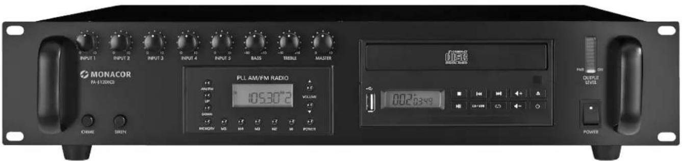
text_image
INPUT 1 INPUT 2 INPUT 3 INPUT 4 INPUT 5 BASS TRENE MASTER PULL AM/FM RADIO AMRUM UP DOWN MENOMY MG MA MD ME M POWER 10530°2 VOLUME OUTPUT LEVEL OUTPUT ON 002:63:49 MONACOR FM-120VCCB ORIME SIRUNPA-8120RCD
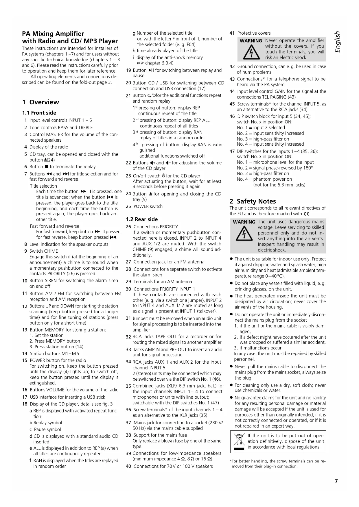
PA Mixing Amplifier with Radio and CD/ MP3 Player
These instructions are intended for installers of PA systems (chapters 1 –7) and for users without any specific technical knowledge (chapters 1 –3 and 6). Please read the instructions carefully prior to operation and keep them for later reference.
All operating elements and connections described can be found on the fold-out page 3.
1 Overview
1.1 Front side
1 Input level controls INPUT 1 - 5
2 Tone controls BASS and TREBLE
3 Control MASTER for the volume of the connected speakers
4 Display of the radio
5 CD tray, can be opened and closed with the button ▲(24)
6 Button ■ to terminate the replay
7 Buttons ◀◀ and ▶▶I for title selection and for fast forward and reverse
Title selection
Each time the button ▶▶ I is pressed, one title is advanced; when the button ◀◀ is pressed, the player goes back to the title beginning, and each time the button is pressed again, the player goes back another title.
Fast forward and reverse
For fast forward, keep button ▶▶ I pressed, for fast reverse, keep button pressed ◀◀.
8 Level indication for the speaker outputs
9 Switch CHIME
Engage this switch if (at the beginning of an announcement) a chime is to sound when a momentary pushbutton connected to the contacts PRIORITY (26) is pressed.
10 Button SIREN for switching the alarm siren on and off
11 Button AM / FM for switching between FM reception and AM reception
12 Buttons UP and DOWN for starting the station scanning (keep button pressed for a longer time) and for fine tuning of stations (press button only for a short time)
13 Button MEMORY for storing a station:
- Set the station
- Press MEMORY button
- Press station button (14)
14 Station buttons M1-M5
15 POWER button for the radio
For switching on, keep the button pressed until the display (4) lights up; to switch off, keep the button pressed until the display is extinguished.
16 Buttons VOLUME for the volume of the radio
17 USB interface for inserting a USB stick
18 Display of the CD player, details see fig. 3
a REP is displayed with activated repeat function
b Replay symbol
c Pause symbol
d CD is displayed with a standard audio CD inserted
e ALL is displayed in addition to REP (a) when all titles are continuously repeated
f RAN is displayed when the titles are replayed in random order
g Number of the selected title or, with the letter F in front of it, number of the selected folder (e. g. F04)
h time already played of the title
i display of the anti-shock memory (Chapter 6.3.4)
19 Button ▶II for switching between replay and pause
20 Button CD / USB for switching between CD connection and USB connection (17)
21 Button ↻ for the additional functions repeat and random replay
1 ^st pressing of button: display REP continuous repeat of the title
2 ^nd pressing of button: display REP ALL continuous repeat of all titles
3 ^rd pressing of button: display RAN replay of titles in a random order
4^th pressing of button: display RAN is extinguished additional functions switched off
22 Buttons ◀+ and ◀- for adjusting the volume of the CD player
23 On/off switch ⏻ for the CD player
After actuating the button, wait for at least 3 seconds before pressing it again.
24 Button ▲ for opening and closing the CD tray (5)
25 POWER switch
1.2 Rear side
26 Connections PRIORITY
If a switch or momentary pushbutton connected here is closed, INPUT 2 to INPUT 4 and AUX 1/2 are muted. With the switch CHIME (9) engaged, a chime will sound additionally.
27 Connection jack for an FM antenna
28 Connections for a separate switch to activate the alarm siren
29 Terminals for an AM antenna
30 Connections PRIORITY INPUT 1
If these contacts are connected with each other (e.g. via a switch or a jumper), INPUT 2 to INPUT 4 and AUX 1/2 are muted as long as a signal is present at INPUT 1 (talkover).
31 Jumper: must be removed when an audio unit for signal processing is to be inserted into the amplifier
32 RCA jacks TAPE OUT for a recorder or for routing the mixed signal to another amplifier
33 Jacks AMP IN and PRE OUT to insert an audio unit for signal processing
34 RCA jacks AUX 1 and AUX 2 for the input channel INPUT 5
2 (stereo) units may be connected which may be switched over via the DIP switch No. 1 (46).
35 Combined jacks (XLR/ 6.3 mm jack, bal.) for the input channels INPUT 1–4 to connect microphones or units with line output; switchable with the DIP switches No. 1 (47)
36 Screw terminals* of the input channels 1 - 4, as an alternative to the XLR jacks (35)
37 Mains jack for connection to a socket (230 V/50 Hz) via the mains cable supplied
38 Support for the mains fuse
Only replace a blown fuse by one of the same type.
39 Connections for low-impedance speakers (minimum impedance 4 Ω, 8 Ω or 16 Ω)
40 Connections for 70V or 100V speakers
41 Protective covers
WARNING

Never operate the amplifier without the covers. If you touch the terminals, you will risk an electric shock.
42 Ground connection, can e.g. be used in case of hum problems
43 Connections* for a telephone signal to be heard via the PA system
44 Input level control GAIN for the signal at the connections TEL PAGING (43)
45 Screw terminals* for the channel INPUT 5, as an alternative to the RCA jacks (34)
46 DIP switch block for input 5 (34, 45); switch No. x in position ON:
No. 1 = input 2 selected
No. 2 = input sensitivity increased
No. 3 = high-pass filter on
No. 4 = input sensitivity increased
47 DIP switches for the inputs 1–4 (35, 36); switch No. x in position ON:
No. 1 = microphone level for the input
No. 2 = signal phase-reversed by 180°
No. 3 = high-pass filter on
No. 4 = phantom power on
(not for the 6.3 mm jacks)
2 Safety Notes
The unit corresponds to all relevant directives of the EU and is therefore marked with €€
WARNING

The unit uses dangerous mains voltage. Leave servicing to skilled personnel only and do not insert anything into the air vents. Inexpert handling may result in electric shock.
- The unit is suitable for indoor use only. Protect it against dripping water and splash water, high air humidity and heat (admissible ambient temperature range 0–40°C).
- Do not place any vessels filled with liquid, e.g. drinking glasses, on the unit.
- The heat generated inside the unit must be dissipated by air circulation; never cover the air vents of the housing.
-
Do not operate the unit or immediately disconnect the mains plug from the socket
-
if the unit or the mains cable is visibly damaged,
- if a defect might have occurred after the unit was dropped or suffered a similar accident,
- if malfunctions occur
In any case, the unit must be repaired by skilled personnel.
- Never pull the mains cable to disconnect the mains plug from the mains socket, always seize the plug.
- For cleaning only use a dry, soft cloth; never use chemicals or water.
- No guarantee claims for the unit and no liability for any resulting personal damage or material damage will be accepted if the unit is used for purposes other than originally intended, if it is not correctly connected or operated, or if it is not repaired in an expert way.

If the unit is to be put out of operation definitively, dispose of the unit in accordance with local regulations.
3 Applications
This amplifier with an RMS output power of 120 W is specially designed for PA systems. Either 100 V or 70 V speakers or low-impedance speakers (minimum impedance 4 Ω) can be used. Features:
4 × input channel, switchable line level or microphone level, with XLR / 6.3 mm jacks and screw terminals
1 × input channel, switchable between two line stereo signal sources, with screw terminals and RCA jacks
1 × screw terminals for the telephone signal
1 × input and output with RCA jacks to insert an audio unit for signal processing (automatic volume control, equalizer etc.)
1 × CD / MP3 player
1 × AM / FM radio
1 × alarm siren, to be switched on via internal and external switch
1 × signal chime, to be activated via momentary pushbutton
1 × priority circuit for INPUT 1
4 Setting Up the Amplifier
The amplifier is designed for insertion into a rack for units with a width of 482 mm (19"), but it can also be used as a table top unit. To ensure sufficient cooling of the amplifier, air must always be able to flow freely through all air vents.
4.1 Installation into a rack
For installation into a rack, the amplifier requires a space of 2 RS (2 rack spaces = 89 mm). To prevent the rack from becoming top-heavy, insert the amplifier into the lower section of the rack. The front plate alone is not sufficient for fixing it safely; additionally use lateral rails or a bottom plate to secure the unit.
5 Connections
Prior to making or changing any connections, switch off the PA-8120RCD and the units to be connected.
Many of the connections are underneath the two protective covers (41), e. g. the connections of the speakers. For connecting, remove the covers.
WARNING

Never operate the amplifier without the covers (41). If you touch the terminals, you will risk an electric shock.
5.1 Speakers
Either connect 100 V or 70 V speakers to the terminals (40) [figs. 4a and 4b] – the maximum load of the amplifier by the speakers is 120W; otherwise, the amplifier may be damaged
or connect a speaker or a speaker group with a total impedance of 4 Ω, 8 Ω or 16 Ω to the terminals (39). The figures 4c to 4n show different ways to obtain the correct impedance, however, there still are further possibilities.
When connecting the speakers, always observe the correct polarity as shown in the figures.
5.2 Microphones
Four microphones with an XLR plug or 6.3 mm plug may be connected to the combined XLR / 6.3 mm jacks (35) of the inputs 1 – 4. For microphones with free connection cables, use the screw terminals (36) as an alternative. When connecting, these terminals can be removed from their plug-in connection for better handling.
The microphone at the input 1 may take priority over all other inputs when a switch connected to the terminals PRIORITY (26) is closed.
1) When connecting a microphone, set the switch No. 1 of the corresponding DIP switch block (47) to the lower position (ON).
2) If a phantom-powered microphone is used, set the switch No. 4 of the corresponding DIP switch block to the lower position (ON). The phantom power supply is only available at the XLR contacts and the screw terminals. Microphones connected via 6.3 mm plugs are not supplied with phantom power.
CAUTION!
- Only use the switch when the unit has been switched off (switching noise).
- Do not connect any unbalanced microphone when the phantom power has been switched on (48 V); the microphone may be damaged.
3) To switch on the high-pass filter, e. g. to improve the speech intelligibility or to suppress subsonic sound, set the switch No. 3 of the corresponding DIP switch block to the lower position (ON).
4) If there is a different phase between two microphones (poor bass reproduction of a sound source), the sound may possibly be improved by switching over the switch No. 2 at one of the corresponding DIP switch blocks.
5.3 Audio units with line output
6 units with line output (mixer, MP3 player, etc.) may be connected:
1) Connect units with a mono output to the combined jacks (35) or to the terminals (36) of the inputs 1 to 4. For basic setting, set the corresponding DIP switches Nos. 1 to 4 (47) to the upper position.
2) Connect units with a stereo output either to the RCA jacks (34) or to the terminals (45) of channel 5. Use the switch No. 1 of the corresponding DIP switch block (46) to select between the input jacks AUX 1 (upper switch position) and AUX 2 (lower switch position ON). If required, use the switches No. 2 and No. 4 to match the level. The volume of the unit connected will be increased in the lower position (ON).
When connecting a stereo unit to one of the inputs 1 to 4, use a stereo-to-mono adapter (e. g. SMC-1 from MONACOR) and an adapter cable (e. g. MCA-154 from MONACOR); otherwise, signal parts may be missing.
3) For switching on the high-pass filter, e. g. to improve the speech intelligibility, set the corresponding DIP switch No. 3 to the lower position (ON).
5.4 Audio units for signal processing
An audio unit (e.g. an equalizer or an automatic volume control) for signal processing can be inserted via the RCA jacks AMP IN and PRE OUT (33). To do this, remove the jumper (31), connect the input of the audio unit to the jack PRE OUT and the output to the jack AMP IN.
Note: A signal interruption occurs in the amplifier if only one of the two jacks (33) is connected or the unit inserted is not switched on, if it is defective or not correctly connected. In this case, the speakers remain mute.
5.5 Recorder or additional amplifier
A recorder and / or another amplifier (e. g. if more speakers are required than allowed) can be connected to the RCA jacks TAPE OUT (32).
The same mono signal is present at both jacks. Neither the control MASTER (3) nor the tone controls BASS and TREBLE (2) will affect this signal. Therefore, the output signals of these jacks can be sent to two different units.
5.6 Telephone system
The telephone system allows to reproduce announcements via the PA system.
1) Feed the signal from the telephone system (line level) to the terminals TEL PAGING (43).
2) During an announcement, adjust the volume with the control GAIN (44).
As soon as a signal is available at the input TEL PAGING, all other input signals, except for the siren signal, will be muted automatically.
5.7 Priority control, talkover
A switch connected to the terminals PRIORITY (26) allows to mute all input signals, except for the input signal of the channel INPUT 1 and the siren signal. Thus, for a good intelligibility, it is possible that only the announcement via channel 1 can be heard.
If the connections PRIORITY INPUT 1 (30) are connected by means of a jumper or a switch, INPUT 2 to INPUT 4 and AUX 1/2 are automatically muted as long as a signal is available at INPUT 1 (talkover).
5.8 Separate switch for the alarm siren
To remotely activate the alarm siren, connect a switch to the terminals SIREN (28).
5.9 Antenna connection and mains connection
1) Connect an FM antenna to the jack FM (27) and an AM antenna to the terminals AM (29). In areas with good reception, the antennas provided can be used.
2) Finally connect the supplied mains cable to the mains jack (37) first and then connect the mains plug to a socket (230 V/50 Hz).
6 Operation
To prevent switching noise, first switch on the units connected, then switch on the amplifier with the POWER switch (25). The yellow LED "PWR ON" of the level indication (8) lights up.
6.1 Amplifier part
1) Turn up the control MASTER (3) until the following adjustments can be heard well.
2) Mix the input signals with the controls INPUT 1 to 5 (1), the signal of the radio part with the buttons VOLUME (16) and the signal of the CD player with the buttons ◀ and ⬆2) or fade them in and out, if required. Always set the volume of the channels which are not used to zero.
3) Adjust the definitive volume with the control MASTER. The LED chain (8) shows the output level. If the red LED frequently lights up, the amplifier is overloaded. Then turn back the control MASTER accordingly.
4) Adjust the sound with the controls BASS and TREBLE (2) in an optimum way.
5) If a switch or a momentary pushbutton is connected to the terminals PRIORITY (26), this switch can be used to mute all signals at INPUT 2 to INPUT 4 and AUX 1/2. Thus, an announcement via the channel INPUT 1 is easier to understand.
If a chime is to sound additionally at the beginning of an announcement when the switch or pushbutton connected is pressed, switch on the chime with the button CHIME (9).
6) For acoustic alarm, the siren can be switched on with the switch SIREN (10).
7) After operation, first switch off the amplifier and then all other units connected.
6.2 Radio part
To switch on the radio part, keep the button POWER (15) pressed until the display (4) lights up. The radio part must always be switched on additionally, also after a power failure or when the amplifier has been switched off and on again with the mains switch (25). Select the volume with the buttons VOLUME (16).
6.2.1 Storing stations
It is possible to store 5 FM stations and 5 AM stations:
1) Select the reception range with the button AM / FM (11). The reception range is shown on the left of the display (4):
FM
AM
2) Keep the button UP or DOWN (12) pressed until the station scanning starts forward or backward.
3) The station scanning stops at the next station. Restart the scanning until the desired station is found.
4) If stations are very close to each other, make a fine adjustment, if required: actuate the button UP or DOWN only for a short time so that the frequency received will be increased or reduced in small steps until the best reception quality is obtained.
5) To store, press the button MEMORY (13). A horizontal segment flashes on the right of the display.
6) Press the station button M1 - M 5 (14) under which the station is to be stored. The display confirms the storing procedure with the indication OK.
7) For all further stations to be stored, repeat the steps. The stations remain stored up to one week after the amplifier has been switched off.
6.2.2 Calling up stored stations
First select the reception range with the button AM / FM (11) [shown on the left of the display] and then the desired station with the corresponding station button M1 to M5 (14). The number of the adjusted station is shown on the right of the display.
6.3 CD/MP3 player
It is possible to replay standard audio CDs including those you have burnt yourself (CD-R). Depending on the CD type, CD burner and burning software used, problems may occur when rewritable CDs (CD-RW) are replayed. MP3 files can be replayed from CDs or via the USB port (17).
6.3.1 Note on sound interruptions and reading errors
Cigarette smoke and dust will easily penetrate through all openings of the unit and also settle on the optics of the laser sampling system. If this deposit causes reading errors and sound interruptions, the unit must be cleaned by skilled personnel. Please note that there will be a charge on cleaning, even during the warranty period!
6.3.2 Replaying titles
1) Switch on the CD player with the button (23). It must always be switched on additionally; also after a power failure or when the amplifier has been switched off and on with the mains switch (25).
Note: After actuating the button, wait for at least 3 seconds before pressing it again. Otherwise, the CD player may be locked. In this case, switch the unit off and on again with the mains switch (25).
2) Open the CD tray (5) with the button ▲(24) and insert a CD with the lettering facing upwards. Close the tray with the button ▲ After the CD has been loaded (indication r ERd), the first title starts automatically [indication ▶ (b)].
3) Additionally or alternatively, a USB stick may be inserted into the USB port (17).
Note: Due to the large number of storage device manufacturers and device drivers, it cannot be guaranteed that all storage media are compatible with the CD/MP3 player.
4) To switch between the USB connection and a CD, press the button CD / USB (20).
5) Adjust the volume of the CD player with the buttons ◀+ and ◀- (22) (indication no vol ... 32 vol).
6) The replay can be interrupted with the button ▶II (19) at any time [indication II (c) appears; the playing time (h) flashes] and be continued.
7) To select another title, shortly press the button ▶▶(7) (to advance one title) or the button ◀◀ (to go back to the title beginning, each time the button is pressed, the player goes back another title). With a CD with several folders (not for standard audio CDs), the titles are replayed and selected in the following order:
1. all titles without folder in the root directory
2. all titles in folders in the root directory
3. all titles in subfolders etc.
8) During the replay, it is possible to advance and go back within a title. To advance, keep the button ▶▶ I pressed; to go back, keep the button ◀◀ pressed.
9) To stop the replay, press the button ■ (6).
6.3.3 Repeat functions and random replay
1) To repeat the title, press the button ⬇(21) once. The display shows REP (a).
2) To repeat all titles of the CD, press the button ⬇ a second time. The display now shows REP ALL (e).
3) To replay the titles in a random order, press the button ⬇a third time. The display now shows RAN (f).
4) To switch off the additional function, press the button ⬇, until the indication RAN will be extinguished.
6.3.4 Anti-shock memory
The anti-shock memory of the CD player will be able to compensate temporary shocks or vibrations occurring during the CD sampling; however, it will not be able to compensate continuous, severe vibrations. The more segments of the memory indication (i) are shown, the longer interruptions can be compensated.
7 Specifications
Amplifier part
Rated power: 120W
THD: 0.5% at 1 W
Speaker outputs: ..... 4/8/16Ω, 70/100V
Inputs (sensitivity, impedance) Microphone
INPUT 1-4: ..... 1.8mV, 5kΩ, bal.
Phantom power supply: = 48 V
Line INPUT 1-4: .....300mV, 5kΩ, bal.
Line AUX 1, AUX 2: . . . 100 mV, 10 kΩ, unbal.
Frequency range: .....50–16 500 Hz, ±3 dB
Tone controls
BASS: ±10 dB at 100 Hz
TREBLE: ....±10dB at 10kHz
S/N ratio: ....> 65 dB
Radio part
Reception range
FM: 87.5-108MHz
AM: 525-1650kHz
Sensitivity FM/AM: ..... 2.5/20μV
S/N ratio FM/AM: .....65/50 dB
General information
Power supply: 230 V/50 Hz
Power consumption: .... max. 365 VA
Ambient temperature: .. 0–40°C
Dimensions (W × H × D): 482 × 110 × 450 mm, 2 RS (rack space)
Weight: 10.5 kg
Subject to technical modification.
All rights reserved by MONACOR® INTERNATIONAL GmbH & Co. KG. No part of this instruction manual may be reproduced in any form or by any means for any commercial use.
6.3.4 Mémoire anti-chocs
TREBLE (agudos): ..... ±10 dB a 10 kHz