EVO 300 SS (2018) - Motorcycle Beta - Free user manual and instructions
Find the device manual for free EVO 300 SS (2018) Beta in PDF.



Frequently Asked Questions - EVO 300 SS (2018) Beta
User questions about EVO 300 SS (2018) Beta
0 question about this device. Answer the ones you know or ask your own.
Ask a new question about this device
Download the instructions for your Motorcycle in PDF format for free! Find your manual EVO 300 SS (2018) - Beta and take your electronic device back in hand. On this page are published all the documents necessary for the use of your device. EVO 300 SS (2018) by Beta.
USER MANUAL EVO 300 SS (2018) Beta
Thanks for you preference, and have a good time! This handbook contains the information you need to properly operate and maintain your motorcycle.
The data, specifications and images shown in this manual does not constitute an engagement on the part of BETAMOTOR S.p.A. BETAMOTOR reserves the right to make any changes and improvements to its models at any moment and without notice.
Code 007440380 000
IMPORTANT
We recommend you to check all the tightenings after the first one or two hours' ride over rough ground. Special attention should be paid to the following parts:
- rear sprocket
- ensure that the footrests are properly fixed
- front/rear brake levers/calipers/discs
- check that the plastics are properly fastened
- engine bolts
- shock absorber bolts/swingarm
- wheel hubs/spokes
rear frame - pipe connections
- tensioning the chain
IMPORTANT
In the event of interventions on the vehicle, contact Betamotor after-sales service.
TABLE OF CONTENTS
Operating instructions 5
Symbols 5
Riding safety 6
CHAPTER 1 GENERAL INFORMATION
Vehicle identification data 8
Familiarizing with the vehicle. 9
Specifications 10
Electrical system 14
Recommended lubricants and liquids 16
Main parts 18
Digital rpm indicator operating instructions. 22
Checks before and after use 26
Breaking in. 26
Fuelling 27
Startup 28
Engine shut-down 28
CHAPTER 3 ADJUSTMENTS 29
Key to symbols. 30
Clutch 30
Adjustment of gas clearance. 31
Accelerator 31
Handlebar adjustment 31
Adjusting fork 32
Shock absorber 32
Suspension adjustment according to the motorcyclist's weight 34
Headlight adjustment 34
CHAPTER 4 CHECKS AND MAINTENANCE 35
Key to symbols. 36
Gear oil 36
Coolant 37
Air filter 39
Spark plug 41
Carburetor 42
Front Brake. 44
Rear brake 47
Clutch control 50
Check of steering gear. 52
Oil fork 53
Tyres. 56
Chain 57
Headlight 59
Rear tail light 60
Turn indicators 60
Cleaning the vehicle 61
Prolonged inactivity 62
Scheduled maintenance vehicle 63
Tightening torque overview 64
CHAPTER 5 REMOving AND INSTALLING SUPERSTRUCTURES....67
Removing and installing saddle-mudguard assembly. 68
CHAPTER 6 TROUBLESHOOTING 69
Troubleshooting 70
OPERATING INSTRUCTIONS
- The vehicle must be accompanied by: number-plate, registration document, tax disc and insurance.
- Changes to the engine or other parts is punishable by law with severe penalties, including the confiscation of the vehicle.
- Do not sit on the vehicle stand.
- Do not start the engine in a closed place.
WARNING
Any modifications and tampering with the vehicle during the warranty period exempt the manufacturer from all responsibility and invalidate warranty.
SYMBOLS

SAFETY/ATTENTION
Failure to respect information marked with this symbol can entail a personal hazard.

INTEGRITY OF THE VEHICLE
Failure to respect information marked with this symbol can entail serious damage to the vehicle and termination of the warranty.

FLAMMABLE LIQUID HAZARD

Read the use and maintenance manual carefully.

MANDATORY TO WEAR PROTECTIVE CLOTHING
Use of the vehicle is subject to wearing specific protective clothing and safety footwear.

PROTECTIVE GLOVES MANDATORY
To perform the operations described, it is mandatory to wear protective gloves.

FORBIDDEN TO USE NAKED FLAMES OR POSSIBLE UNCONTROLLED IGNITION SOURCES

NO SMOKING

DO NOT USE MOBILE PHONE

CORROSIVE SUBSTANCES HAZARD
Liquids marked with this symbol are highly corrosive: handle with care

POISONING HAZARD
RIDING SAFETY
- Observe the Highway Code.
Always wear approved personal safety equipment.
Always ride with the low beam on.
Always keep the crash helmet visor clean. - Avoid wearing garments with hanging ends.
- Do not keep sharp or brittle objects in your pockets while riding.
- Properly adjust the rearview mirrors.
- Always ride in a seated position, with both hands on the handlebars and both feet on the footrests.
- Never ride abreast with other vehicles.
- Do not tow and avoid being towed by other vehicles.
- Always keep a safe distance from other vehicles.
- Do not start off while the vehicle is on its stand.
- Avoid swaying and wheelies as they are extremely dangerous for your own and other people's safety as well as for your vehicle.
- Always apply both brakes on dry roads with no gravel and sand. Using one brake may be dangerous and cause uncontrolled skidding.
- To reduce the braking distance, always apply both brakes.
- On wet roads and in off-road riding, drive with care and at moderate speed. Take special care in applying the brakes.
CHAPTER 1 GENERAL INFORMATION
CONTENTS
Vehicle identification data 8
Frame identification 8
Engine identification 8
Familiarizing with the vehicle. 9
Main parts. 9
Specifications 10
Weight 10
Vehicle dimensions 10
Tyres 10
Capacities 10
Front suspension 11
Rear suspension 11
Front brake 11
Rear brake 11
Engine 12
Carburetor. 12
Gear box 13
Electrical system. 14
Electrical diagram 14
Legend electrical diagram 15
Recommended lubricants and liquids. 16
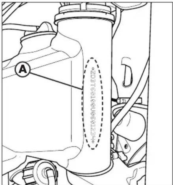
VEHICLE IDENTIFICATION DATA
FRAME IDENTIFICATION
Frame identification data A are stamped on the right side of the steering head tube.
ENGINE IDENTIFICATION
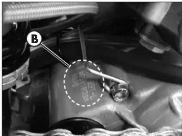
Engine identification data B are stamped in the area shown in the picture.
WARNING:
Tampering with the identification numbers is severely punished by law.
FAMILIARIZING WITH THE VEHICLE 19
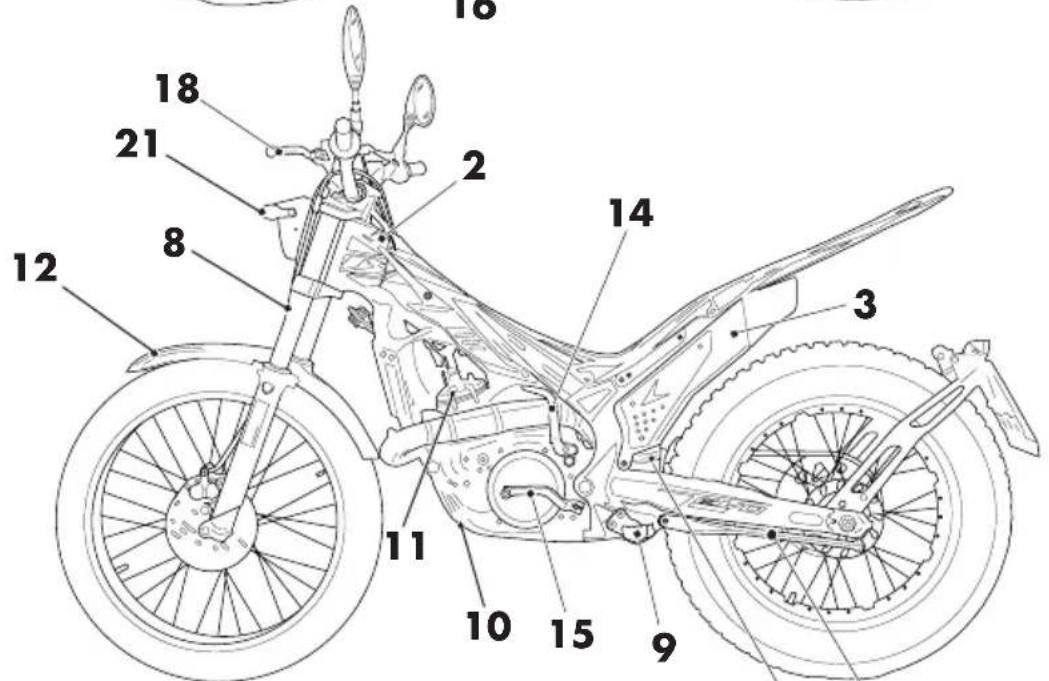
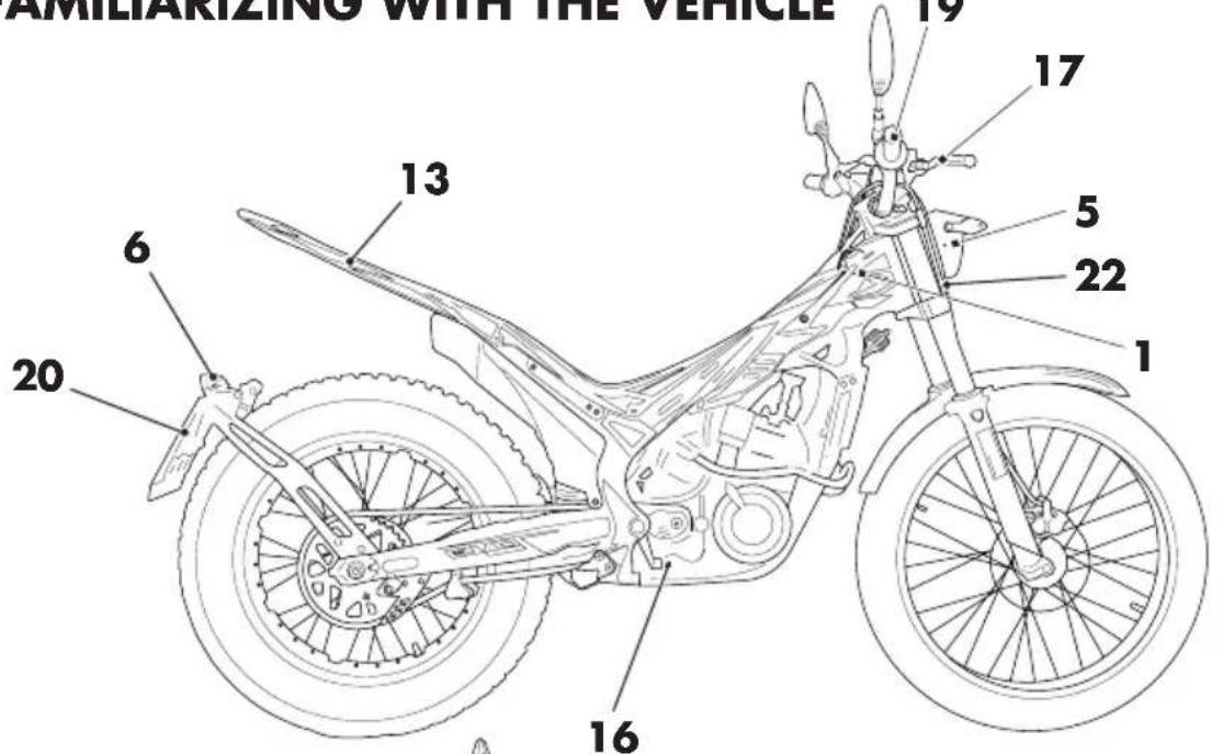
MAIN PARTS
Fuel tank
2 Tank cap
3Silencer
4 Rear shock absorber
5 Headlight
6 Rear light
7 Side stand
8 Fork
9 Rider's footrests
10Lowerbumper
1 Engine
12Frontmudguard
13 Rear mudguard
14 Kick-start
15Gearlever
16 Rear brake lever
17 Front brake lever
18Clutchlever
19 Throttle
20 Number-plate holder
21 Turn indicators
22 Horn
SPECIFICATIONS
WEIGHT
| Version EVO 125 EVO 250 EVO 300/300$S | |||
| Dry weight [kg] 76 77 | 77 | ||
| Front [kg] 38 38.5 38.5 | 5 | ||
| Rear [kg] 38 38.5 38.5 | 5 | ||
VEHICLE DIMENSIONS
maximum length. 2020 mm
maximum width 850 mm
wheelbase 1305 mm
maximum height 1115 mm
ground clearance 310 mm
saddle height 660 mm
TYRES
| Dimensions | Pressure [Bar] | ||
| Front tyre | Rear tyre | Front tyre Rear tyre | |
| 2.75 - 21 | 4.00 - 18 | 0.4 ÷ 0.5 | 0.3 ÷ 0.4 |
CAPACITIES
fuel tank 2.8 litri
including reserve. 0.5 litri
coolant circuit:
| Version EVO 125 EVO 250 EVO | 300/300SS | ||
| With dry circuit [ml] | 630 | 530 | 530 |
| With circuit emptied [ml] | 530 | 420 | 420 |
gear oil. 550 ml
FRONT SUSPENSION
| Version EVO 125 EVO 250 EVO 300/300SS | ||||||
| Wheel excursion [mm] | 166 166 1 | 66 | ||||
| right fork leg | left fork leg | right fork leg | left fork leg | right fork leg | left fork leg | |
| K spring [N/mm] X 7.65 X 7.65 X 7.65 | ||||||
| Oil type Shell Tellus S2 | V32 SAE 6,1 | |||||
| Oil quantity [g] 297 | ||||||
| Register spring preload | X | full open | X | full open | X | full open |
| Click in extension | full open | X | full open | X | full open | X |
REAR SUSPENSION
| Version EVO 125 EVO 250 EVO 300/300SS | |||
| k spring | 70N/mm | 70N/mm | 70N/mm |
| precharge (spring in its seat) [mm] | 126.5 | 126.5 | 126.5 |
| Oil type | oil titan SAF 5045 Eu 137 RED | ||
| Click in extension | 3.5 from fully closed | 3.5 from fully closed | 3.5 from fully closed |
FRONT BRAKE
disk-type with hydraulic control 185mm
REAR BRAKE
disk-type with hydraulic control 160mm
ENGINE
| Version EVO 125 EVO 250 EVO 300 EVO 300SS | ||||
| Type | Single-cylin- der, 2-stroke | Single-cylin- der, 2-stroke | Single-cylin- der, 2-stroke | Single-cylin- der, 2-stroke |
| Bore x stroke 54 x 54.5 72.5 x 60.5 79 x 60.5 | ||||
| Displacement [cm3] | 124.8 249.7 | 296.5 296.5 | ||
| Pressure ratio 15.9:1 9:1 10.17:1 | 9.96:1 | |||
| CO2 [g/km] 60 68 | 66 66 | |||
| Fuel consumption [l/100km] | 2,6 | 2,9 | 2,8 | 2,8 |
| Fuel system | carburetor without mixer (1.5%) | carburetor without mixer (1.5%) | carburetor without mixer (1.5%) | carburetor without mixer (1.5%) |
CARBURETOR
| EVO 125 | EVO 250 | EVO 300/300SS | |
| Carburetor type | PWK 28 PWK 28 | PWK 28 | |
| Main jet | 85 | 80 | 75 |
| Slow jet | 42 | 38 | 38 |
| Start jet | 60 | 60 | 60 |
| Needle | LHQ | LHQ | LHQ |
| Needle position (from top) | 3° | 3° | 3° |
| Air screw turns (from all closed) | 2 | 2 | 2 |
Cooling system. forced liquid circulation by pump
Spark plug. NGK IR GR7CI-8
Clutch wet, multidisc
GEARBOX
| Version EVO 125 EVO 2 | 50 EVO 300/ | 300SS | |
| Primary drive | 20/71 22/69 | 22/69 | |
| Gear ratio 1st gear | 12/34 12 | /34 12/34 | |
| Gear ratio 2nd gear | 14/32 14 | /32 14/32 | |
| Gear ratio 3rd gear | 15/29 15 | /29 15/29 | |
| Gear ratio 4th gear | 18/27 18 | /27 18/27 | |
| Gear ratio 5th gear | 24/22 24 | /22 24/22 | |
| Gear ratio 6th gear | 28/18 28 | /18 28/18 | |
| Secondary drive | 43/9 42/ | 1 42/11 | |
Ignition .electronic Hidria 12V-110W
1
ELECTRICAL SYSTEM
ELECTRICAL DIAGRAM
GENERAL INFORMATION
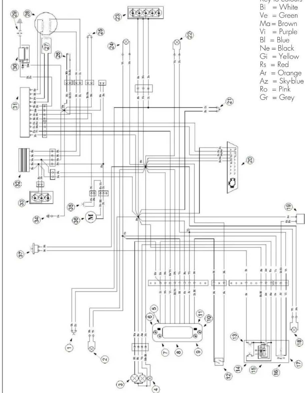
LEGEND ELECTRICAL DIAGRAM
1) Stop button
2) R.H. front turn indicator 12V 6W
3) Headlamp 12V 35/35W
4) Position light 12V 5W
5) "Select" button
6) Diagnosys warning light
7) R.h. turn indicator warning light
8) Dashboard
9) High beam warning light
10) L.h. turn indicator warning light
11) "Mode" button
12) Speed sensor
13) Horn button
14) Unit turn signal lamps
15] Light switch
16) Turn signal switch
17) Control group
18) L.H. front turn indicator 12V 6W
19) Intermittence
20) Socket OBD
21) Rear brake stop button
22) L.H. rear turn indicator 12V 6W
23) Rear stop light Led
24) R.H. rear turn indicator 12V 6W
(25) Engine stop button
26) Switch for change mapping
27)Pick-up
28) Stator
29) Spark plug
30) Coil
31) Electronic control unit
32) Regulator
33) Front light led
34) Frame earth
35) Thermal switch
36) Electrofan
37) Horn
RECOMMENDED LUBRICANTS AND LIQUIDS
For better operation and longer vehicle life, we advise you to use the products listed in the following chart:
| PRODUCT TYPE SPECIFICATIONS | |
| OILMIXTURE LIQUI MOLY RACING SYNTH 2T | |
| GEAR AND CLUTCH OIL LIQUI MOLY RACING 4T 10W-30 | |
| BRAKE OIL LIQUI MOLY BRAKE FLUID DOT4 | |
| CLUTCH ACTUATOR OIL LIQUI MOLY BRAKE FLUID DOT4 | |
| FORK OIL SHELL TELLUS S2 V32 - SAE 6.1 | |
| TIE ROD GREASE LIQUI MOLY SCHMIERFIXIX | |
| LIQUID COOLANT | LIQUI MOLY COOLANT READY MIX RAF12 PLUS |
CHAPTER 2 OPERATION
CONTENTS
Main parts 18
Fuel valve 18
Starter. 18
Clutch lever 18
LH switch. 19
RH switch 19
Front brake lever and gas control 19
Gearchange lever. 20
Brake pedal 20
Kick-start 20
Keys 21
Device against unhaotorised use. 21
Digital rpm indicator operating instructions 22
Main parts 22
Warning lights 22
Adjust button function instruction 23
1. Select button function instruction 24
To enter the setting mode 24
Checks before and after use 26
Breaking in 26
Fuelling 27
Startup 28
Engine shut-down 28
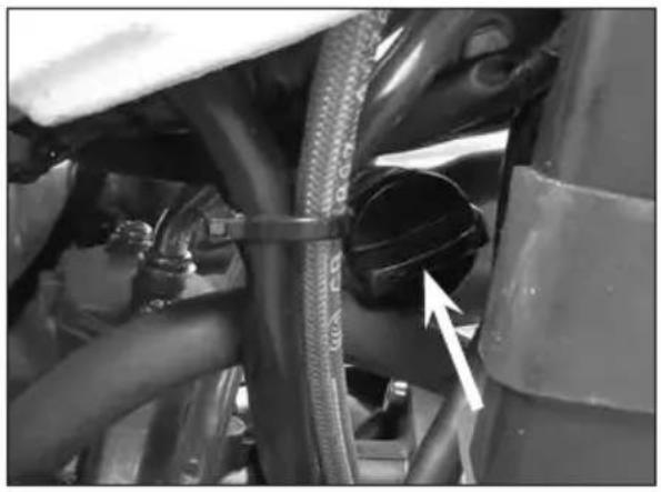
MAIN PARTS
FUEL VALVE
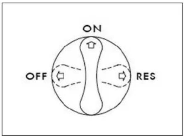
Fuel valve has three positions:
OFF: fuel supply closed. Fuel cannot pass from the tank to the carburettor.
ON: fuel supply enabled. Fuel flows from the tank to the carburettor. The tank empties until it reaches the reserve level.
RES: reserve fuel supply. Fuel flows from the tank to the carburettor and the tank empties completely.
Attention!
During competition use or extreme "trial zone" is advising to position the fuel tap on "RES" to guarantee an optimal fuel supply in all condition use.
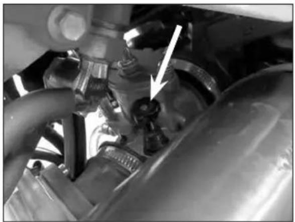
STARTER
The starter lever is located on the carbu-reffor.
To operate the lever pull up.
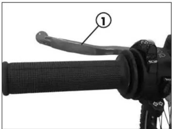
CLUTCH LEVER
Clutch lever 1 is fitted to the left-hand side of the handlebars.
LH SWITCH
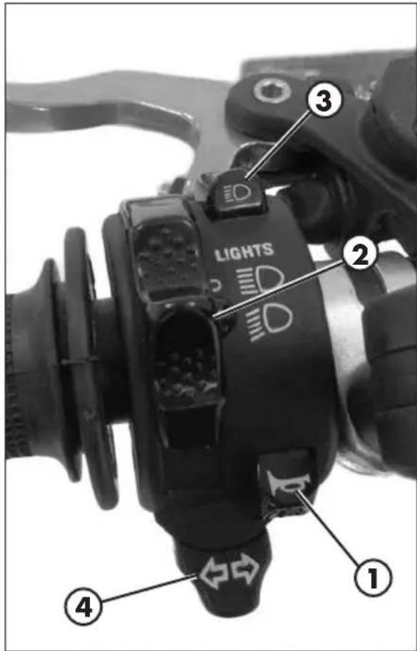
The dip and service switch is located on the left side of the handlebar and is composed as follows:
1 - Horn button;
2 - Dip switch:

daylight lights and high beam;

daylight lights and low beam;
3-Flash-to-pass button;
4 - Turn signal light switch: shifting lever left or right activates the left or right indicators; To disable direction indicators, move the lever to the centre position.
RH SWITCH
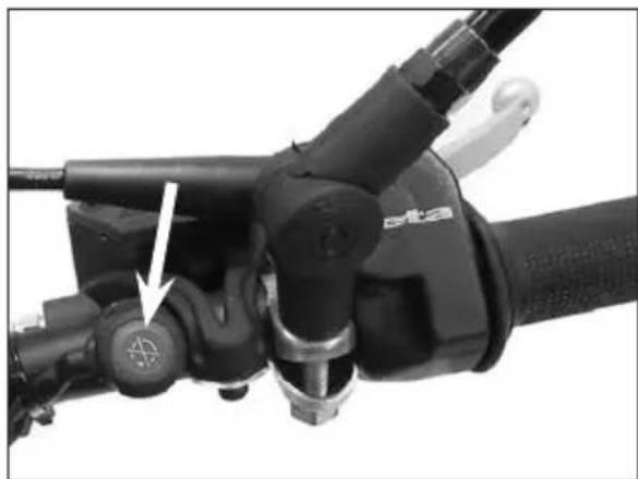
The off switch is positioned on the right-hand side of the handlebar and consists of the following:
shutdowns engine: it is necessary to hold it until the engine stops.
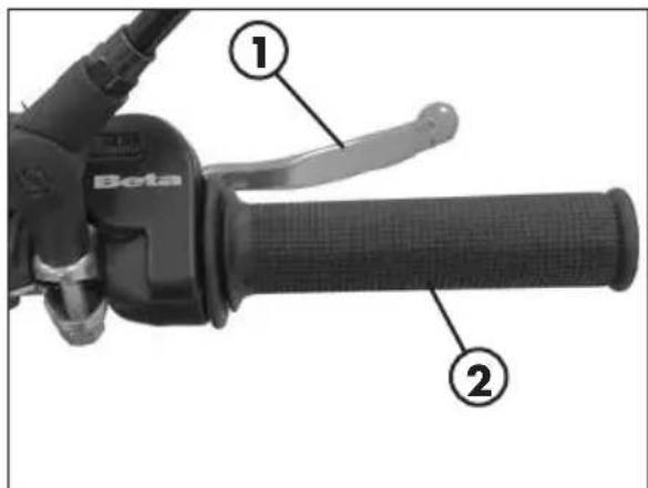
The front brake lever 1 and the gas throttle 2 are located on the right side of the handlebar.
GEARCHANGE LEVER
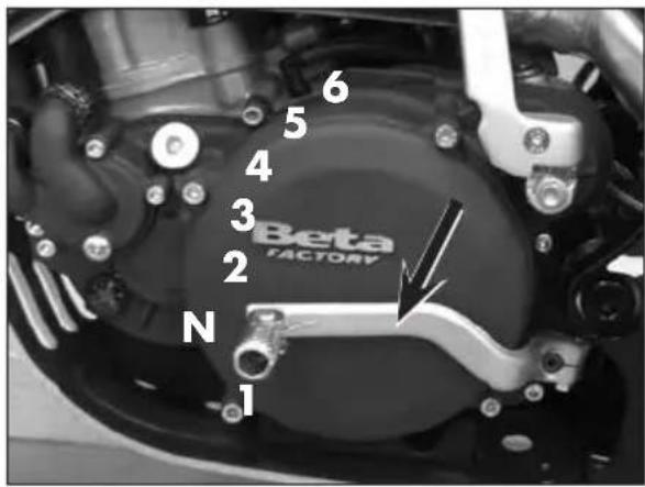
Gearchange lever is fitted to the left side of the engine.
The positions corresponding to the different gears are shown in the figure.
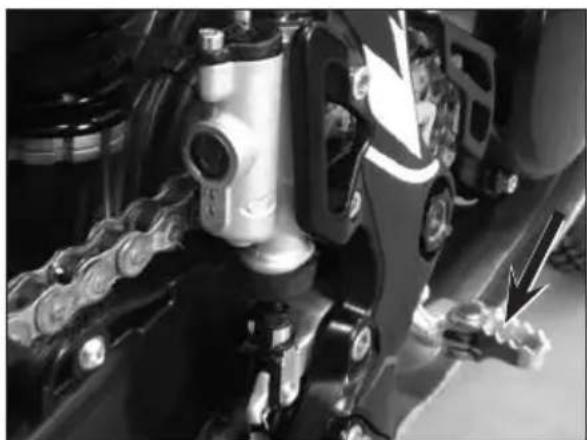
BRAKE PEDAL
Brake pedal is located in front of the right-hand footrest.
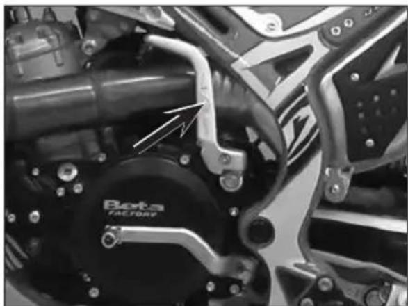
KICK-START
The kick-start pedal is located on the left side of the engine. The upper part is rotatable.
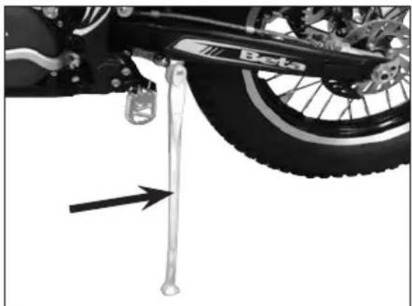
SIDE STAND
Press down side stand with the foot and lean the vehicle against it.
Ensure that the ground is solid and the vehicle stands steadily.

WARNING! The kickstand has an automatic closing device. When the vehicle weight on the kickstand is reduced, it closes automatically.

ATTENTION! Do not climb on the vehicle with the side stand lowered.
KEYS
The vehicle is supplied with two keys (one key and its spare).
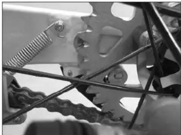
DEVICE AGAINST UNHAUSERISED USE
To enable the device:
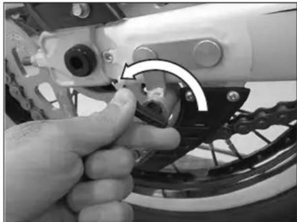
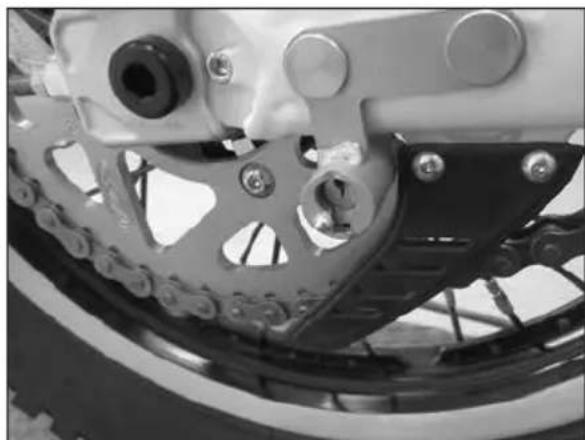
Turn the wheel until one of the windows on the ring gear completely uncovers the locking device pin;
Insert the key into the lock, turn counterclockwise and push it until the pin reaches stroke end. From this position, turn the key clockwise and remove it. In so doing, the rear wheel will be locked.
To disable the device:
- Insert the key into the lock and turn counterclockwise;
- Release the key until the pin is in a rest position. From this position, the rear wheel can move freely
CAUTION: Do not keep the spare key in the motor bike but place it in a safe place. We suggest noting down the number stamped on the keys in case you need a duplicate.

ATTENTION! Before starting up the vehicle, make sure you have switched off the device.
DIGITAL RPM INDICATOR OPERATING INSTRUCTIONS
MAIN PARTS
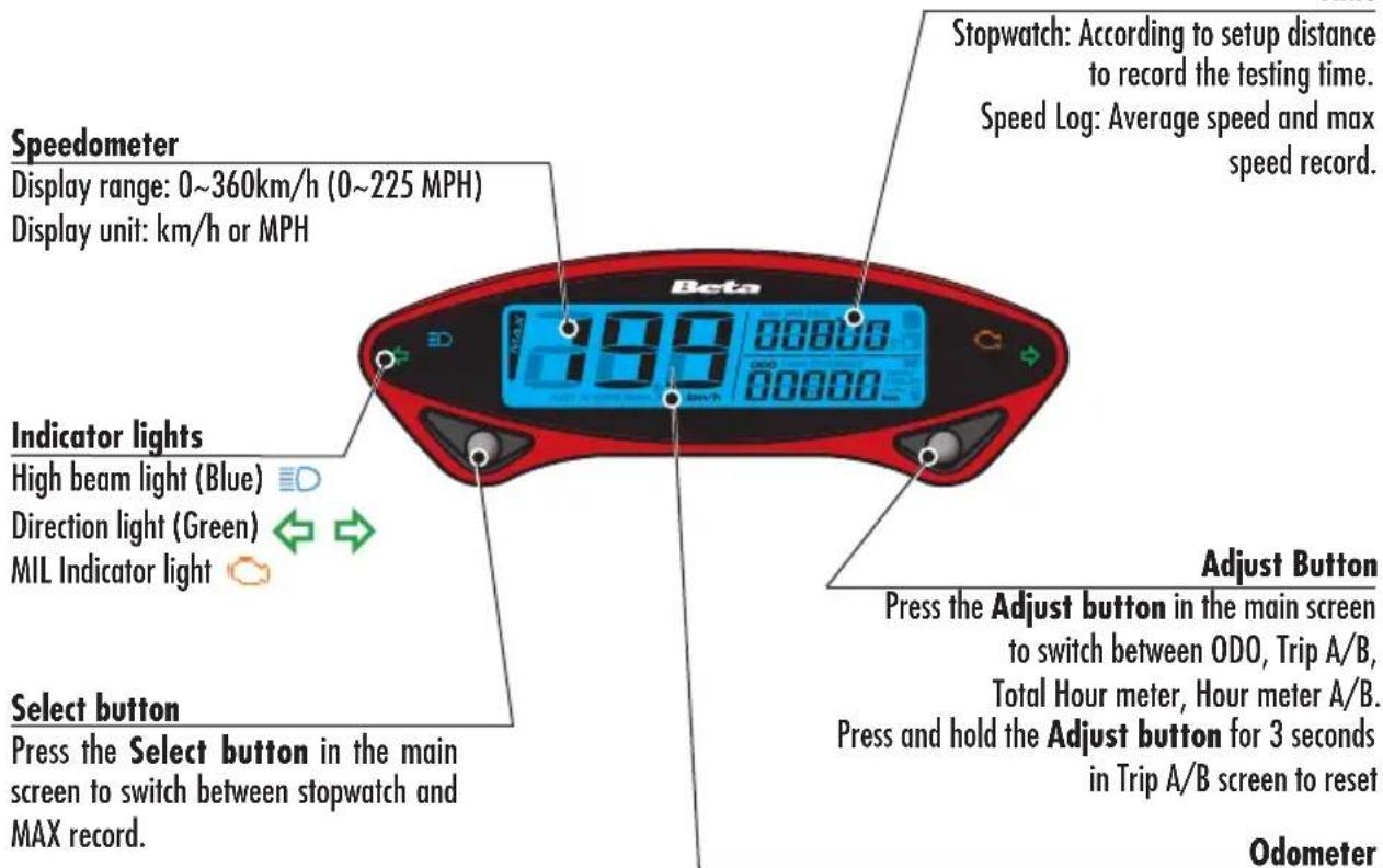
Time
Note:
Switching on the instrument coincides with the engine ignition. Settings can be performed only with the engine running.
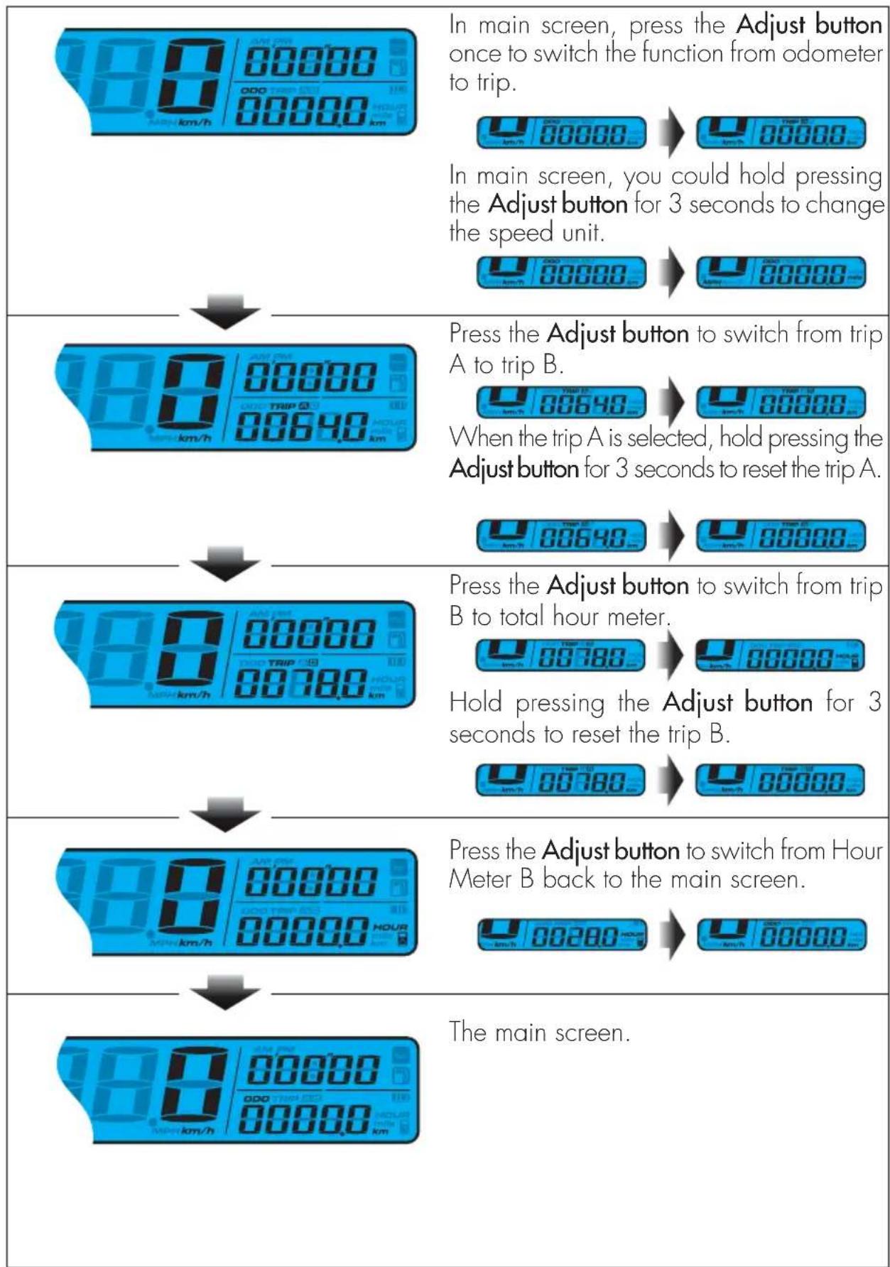
Display range: 0 99999 km (mile), reset automatically after 99999km mile
Display unit: 1km (mile).
Tripmeter
Display range: 0 9999.9km (mile), reset automatically
after 999.9km (mile).
Display unit: 0.1km (mile).
WARNING LIGHTS
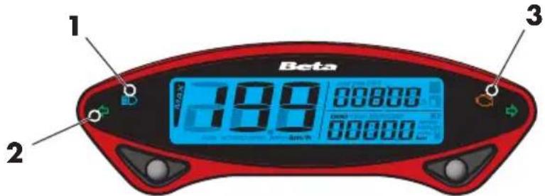
1 Headlight indicator The system activates the indicator in synchrony with the activation of the mains beams.
2 Direction indicator lights The system activates the indicator in synchrony with the activation of the direction indicators.
3 Diagnostic indicator light The system activates the light when a technical problem is detected.
ADJUST BUTTON FUNCTION INSTRUCTION
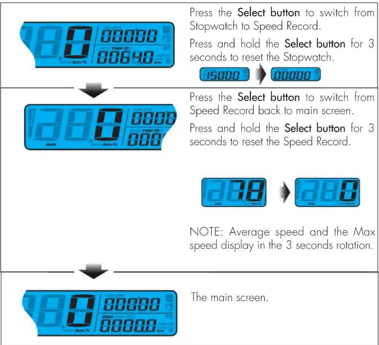
SELECT BUTTON FUNCTION INSTRUCTION
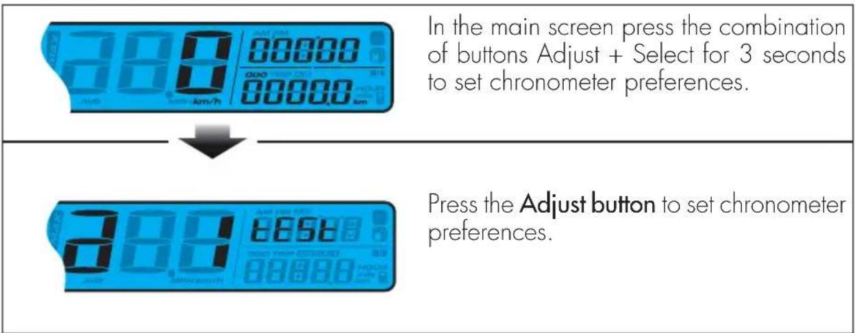
TO ENTER THE SETTING MODE
Function instruction
Distance setup for Stopwatch
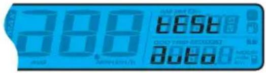
Press the Select button to choose auto/ manual stopwatch function.
If Auto is chosen, press the Select button to exit the stopwatch setting function.

NOTE: Default: AUTO
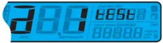
Switch from a to a
Press Select button to switch to total Mileage setting screen.
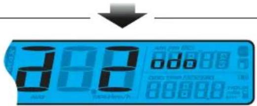
Press the Adjust button to set the speedometer.
ODO setting
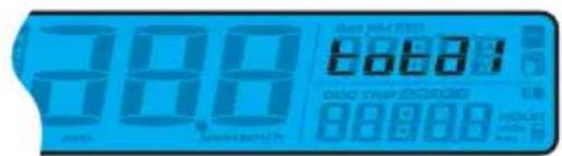
Press the Adjust button to enter the actual ODO viewing display.
Press the Select button to enter the User ODO setting.
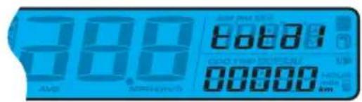
Press Adjust button to enter the User ODO setting.
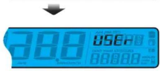
Press the Adjust button to back to ODO adjust function.
Press Select Button to switch to ODO viewing adjusting function.
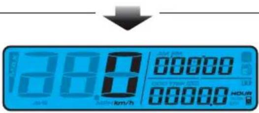
In Setting Screen, press and hold the both Adjust and Select button for 3 seconds to exit the setting.
CHECKS BEFORE AND AFTER USE
For safe driving and long vehicle life you should:

- Check all fluid levels.

- Check the correct operation of the brakes and brake pad wear (page 46).

-
Check pressure, general condition and thickness of tread (page 10).
-
Check that the spokes are properly tightened.
- Check the chain tension (page 57).

- Check the adjustment and the operation of all the cable controls.

-
Inspect all the nuts and bolts.
-
With the engine running, check the operation of the headlight, the rear and brake lights, the indicators, the warning lights and the horn.
- Wash the motorcycle thoroughly after off-road use (page 61).
BREAKING IN
The breaking-in period lasts approximately 5 hours, during which it is advisable to:
- Avoid travelling at constant speed.
- Avoid turning the throttle more than 3/4 of the way.
WARNING:
After the first 5 hours to replace the gearbox oil.
This procedure should be followed each time piston, piston rings, cylinder, crankshaft or crankshaft bearings are replaced.
FUELLING
Use a blend of high-octane unleaded gasoline and synthetic oil at 1.5% .
Fuel tank capacity is shown on page 10.page 10.
To open the fuel tank's cap, turn it anticlockwise.
To close the fuel tank's cap, set it on the tank and crew it clockwise.
For the type of oil mixture refer to the "Recommended fluids and lubricants" table.

WARNING:
The refuelling should be performed with the engine off.

WARNING:
Fire hazard. Fuel is highly flammable.


Always stop the engine when refuelling and keep open flames and lighted cigarettes away.

Do not top up fuel while using a mobile phone.
Refuel in an open well ventilated area.
Pay special attention so that the fuel does not come into contact with hot parts of the vehicle. Immediately clean up any spilled fuel.

WARNING: Risk of poisoning.
Fuel is poisonous liquid and a health hazard.

Fuel must not come into contact with the skin, eyes, and clothing. Do not breathe in the fuel vapours. If contact occurs with the eyes, rinse immediately with plenty of water and seek medical advice. If contact occurs with skin, immediately clean contaminated areas with soap and water. If fuel is swallowed, contact a doctor immediately. Change clothing that is contaminated with fuel.
WARNING: Environmental pollution hazard.
The fuel must not contaminate the ground water, the ground, or the sewage system.
STARTUP
Set the fuel tank tap to ON or RES (see page 18).
- Check that the gears are in neutral (page 20).
- Pull the clutch lever (page 18).Pull the clutch lever (
KICKSTART (page 20):
depress the kick-starter with a sharp movement of the foot.

ATTENTION
Once the pedal has been depressed, release it immediately. This avoids jolts to the entire ignition group and to the foot.
COLD STARTING:
actuate the starter by pulling it upwards (page 18), start the engine, wait a few seconds, then return the lever to its original position.
ENGINE SHUT-DOWN
To shutdown the engine:
- press the button on the right switch unit (see page 19).(see page 19)
NOTE:
With the engine stopped, always set the fuel tap to OFF (page 18).
CHAPTER 3 ADJUSTMENTS
CONTENTS
Key to symbols. 30
Clutch 30
Adjustment of gas clearance. 31
Accelerator 31
Adjusting the idle speed 31
Handlebar adjustment 31
Adjusting fork 32
Adjusting the rebound damper 32
Adjusting the spring preload 32
Shock absorber 32
Adjusting the rebound damper 32
Adjusting the spring preload 33
Suspension adjustment according to the motorcyclist's weight 34
Headlight adjustment 34
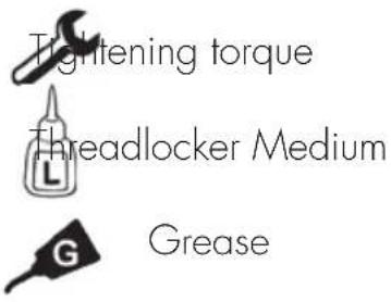
KEY TO SYMBOLS

CLUTCH
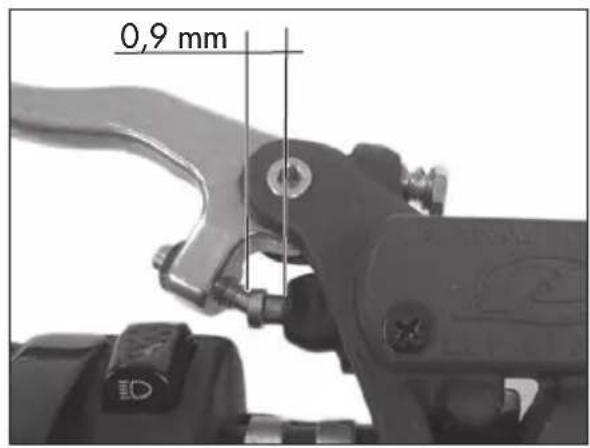
The position of the lever is controlled through the use of register 1.
Once the position of the lever has been changed, register 2 must be changed to restore the initial correct clearance.
The idle stroke of push rod must not be less than 0.9 mm
ATTENTION: reduced clearance leads to premature wear of the discs and overheating of the entire clutch group.
ADJUSTMENT OF GAS CLEARANCE
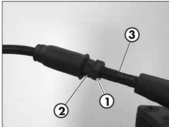
The throttle control cable should always have a 3-5 mm play. In addition, the idle speed should not change when the handlebars are fully rotated to the left or right.
To adjust the clearance proceed as follows:
- Loosen ring 1.
- Rotate register 2 with respect to sheath 3.
- Tighten ring 1.
ACCELERATOR
ADJUSTING THE IDLE SPEED
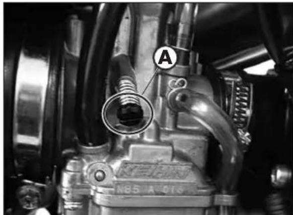
In order to perform this operation correctly, we advise you to do it when the engine is hot, connecting an electric revolution counter to the spark plug wire. Then use a screwdriver on register screw A to calibrate the minimum with 900 ÷ 1000 rpm.
HANDLEBAR ADJUSTMENT
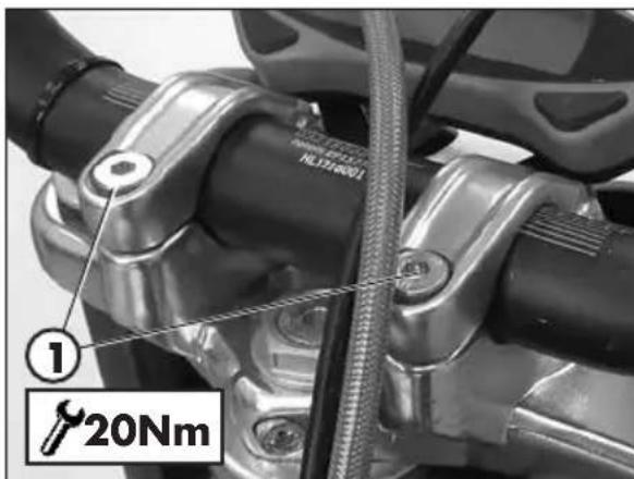
The handlebar can be adjusted by rotating it back and forth.
- To adjust the handlebar loosen screws 1.
- Position the handlebar according to requirements.
- Tighten to the torque indicated.
ADJUSTING FORK
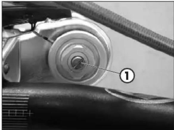
The hydraulic brake unit in extension determines the behaviour in the extension phase of the fork and can be adjusted using screw 1. Turning clockwise increases the action of the brake in extension, while rotating counterclockwise decreases the action of the brake in extension.
For standard calibration, refer to page 11.
ADJUSTING THE SPRING PRELOAD
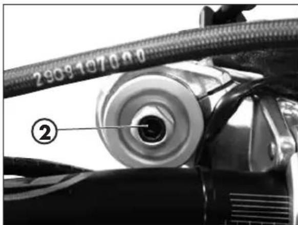
Spring preload is adjusted by means of screw 2. Turning clockwise will increase the preload, while rotating counter-clockwise decreases the preload.
For standard calibration, refer to page 11.
SHOCK ABSORBER
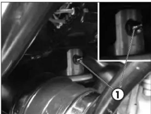
The hydraulic brake unit in extension determines the behaviour in the extension phase of the shock absorber and can be adjusted using screw 1. Turning clockwise increases the action of the brake in extension, while rotating counter-clockwise decreases the action of the brake in extension. For standard calibration, refer to page 11.
NOTE: for adjustment use a T-handle wrenches with jointed hexagonal socket.
ADJUSTING THE SPRING PRELOAD
To adjust the spring preload, use the procedure described below.
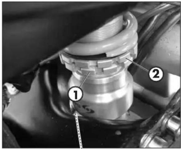
Loosen counter-ring 1, rotate ring 2 clockwise to increase the spring preload (and consequently the shock absorber preload) or anticlockwise to decrease it.
After obtaining the desired preload, turn counterring 1 until it stops against adjusting ring 2.
For standard calibration, refer to page 11.
NOTE: for movement of the rings use a specific sector key with square pin.
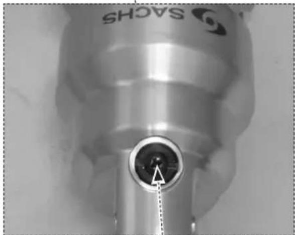
ATTENTION! Do not move the screw 3 under any circumstances.
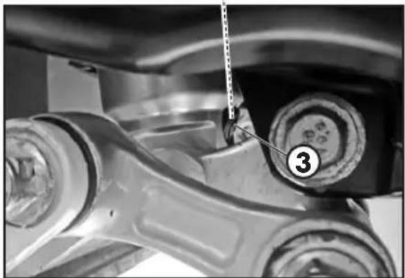
3
SUSPENSION ADJUSTMENT ACCORDING TO THE MOTORCYCLIST'S WEIGHT
The following table shows the approximate calibration of the suspension adjustment according to the motorcyclist's weight.
| p < 70 Kg 70 Kg | < p < 80 Kg 80 Kg | < p | |||
| Adjustment Adjustment | Adjustment | ||||
| Fork | Shock absorber | Fork | Shock absorber | Fork | Shock absorber |
| Standard | Standard | + 5 turns preload | + 1,5 turns preload | + 10 turns preload | + 3 turns preload |
ATTENTION! Shock absorber pre-load max permitted = +6 turns.

HEADLIGHT ADJUSTMENT
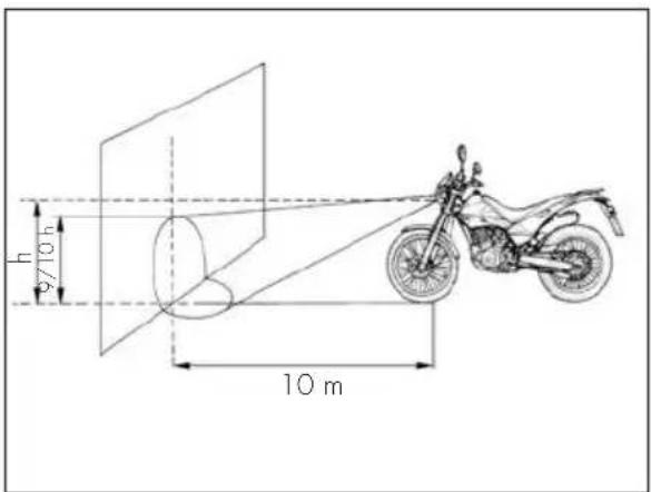
The beam is adjusted by changing the inclination of the optical unit by turning the screw 1 and the nut 2.
- Place the vehicle on level ground (but not on the stand) 10 metres from a vertical wall.
Measure the height of the headlight centre above the ground and then draw a cross on the wall at 9/10 of the height of the headlight centre.
- Sit on the motor bike with only the high beam headlight on and check that the headlight beam on the wall is slightly lower than the cross drawn previously. Where this is not the case, proceed to adjustment.
Periodically check the direction of the beam. The beam can only be adjusted vertically.
When adjustment is complete, make sure that nut 2 is fully tightened towards the instrument support.
CHAPTER 4 CHECKS AND MAINTENANCE
CONTENTS
Key to symbols. 36
Gear oil 36
Check the level. 36
Replacement 36
Coolant 37
Check the level 37
Replacement 38
Radiator grill 39
Air filter 39
Removing and fitting air filter 39
Cleaning air filter 40
Spark plug 41
Carburetor 42
Draining the carburetor float chamber. 42
Float level check 43
Front Brake 44
Check the level of the front brake fluid 44
Restoring the level of the front brake fluid 44
Bleeding the front brake 45
Front brake lining control 46
Brake disc thickness control 46
Rear brake 47
Check the level of the rear brake fluid 47
Restoring the level of the rear brake fluid 47
Bleeding the rear brake 48
Rear brake lining control 49
Brake disc thickness control 49
Clutch control 50
Check oil level 50
Bleeding clutch control 51
Check of steering gear. 52
Oil fork 53
Removing legs 53
Oil replacement right leg 53
Oil replacement left leg 54
Legs assembly and parts. 55
Tyres. 56
Linkage rear suspension 56
Chain 57
Check and adjust tightening chain 57
Headlight 59
Replacing the headlight bulbs 59
Rear tail light 60
Turn indicators 60
Cleaning the vehicle 61
General precautions 61
Prolonged inactivity 62
Scheduled maintenance vehicle 63
Tightening torque overview 64
4
CHECKS AND MAINTENANCE

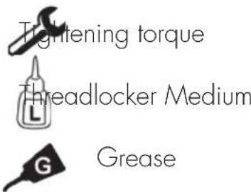
KEY TO SYMBOLS
GEAR OIL
CHECK THE LEVEL
Keep the vehicle in vertical position relative to the ground.
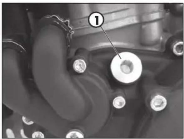
When engine is cold check the oil level by means of porthole 1. The oil level must be always visible from the porthole.
In contrary case restore the oil level through filler cap 2.
Use the liquid indicated on page 16 in the "Recommended lubricants and liquids" table.
REPLACEMENT
Always perform the replacement when engine is hot:
- Position the drive on a flat base ensuring stability
- Place a container under the engine
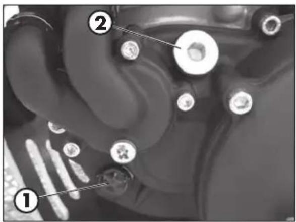
- Unscrew the filler cap 1 and the drain plug 2
- Completely empty the crankcase
- Close the cap 2
- Introducing the quantity of liquid shown at page 10.
Use the liquid indicated on page 16 in the "Recommended lubricants and liquids" table. - Close the filler cap 1.
WARNING: Hot oil can cause severe burns!
COOLANT
CHECK THE LEVEL
Keep the vehicle in vertical position relative to the ground.
The level of the coolant must be checked when the engine is cold. Use the following procedure:
-
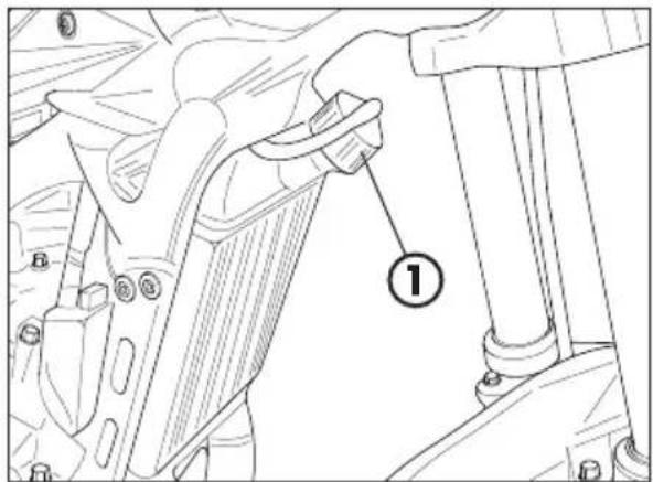
Unscrew cap 1 and ensure that the liquid is visible in the lower portion of the loading tube.
-
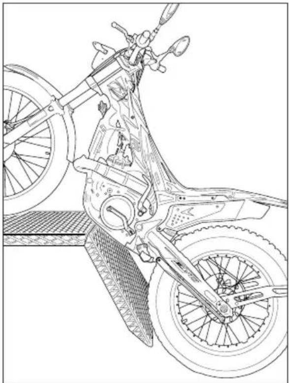
Where the liquid is not visible in the lower part of the loading tube position the vehicle as in the figure and then top up.
- At the end of operation refit the filler cap and the vent screw.
Use the liquid indicated on page 16 in the "Recommended lubricants and liquids" table.

WARNING: Never unscrew the filler cap of the radiator when the engine is hot. Danger of burning!

WARNING: Wear appropriate protective clothing and protection gloves.

Keep coolant out of reach of children.

Avoid any direct contact of the coolant with skin, eyes or clothing. If this happens:
with the eyes, rinse immediately with plenty of water and seek medical advice;
with skin, Immediately clean contaminated areas with soap and water Change clothing that is contaminated with coolant.
If coolant is swallowed, contact a doctor immediately.
4
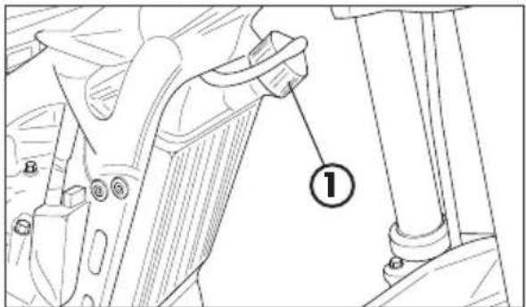
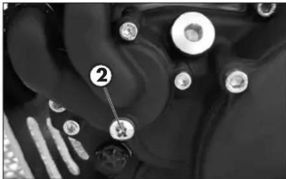
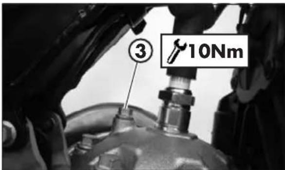
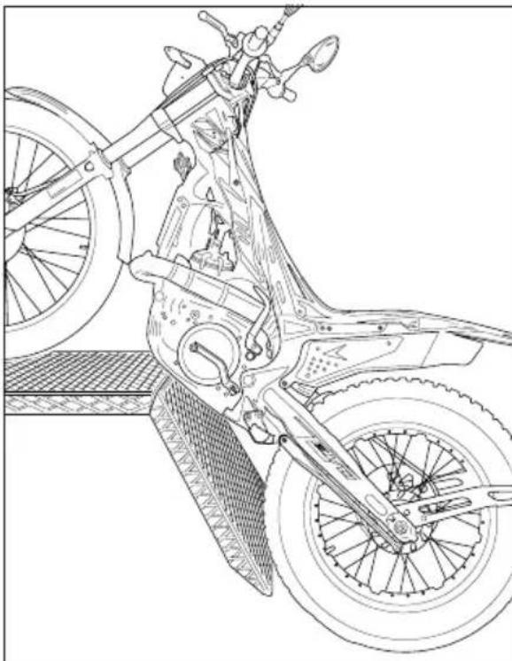
REPLACEMENT
Position the vehicle on a flat base and in a stable manner.
Replacement of the coolant must take place when the engine is cold.
1) Unscrew cap 1.
2) Place a container under screw 2.
3) Unscrew the screw 2.
4) Drain the liquid.
5) Tighten screw 2 applying the specific washer.
6) Unscrew drain screw 3 and fill until the liquid starts to overflow the screw.
7) Tighten screw 3.
8) Place the vehicle as shown and proceed to filling.
9) Reapply the loading cap 1.
The amounts of liquid are shown on page 10.
Use the liquid indicated on a page 16 in the "Recommended lubricants and liquids" table.

WARNING:
Never unscrew the filler cap of the radiator when the engine is hot. Danger of burning!

WARNING:
Wear appropriate protective clothing and protection gloves.

Keep coolant out of reach of children.

Avoid any direct contact of the coolant with skin, eyes or clothing. If this happens:
with the eyes, rinse immediately with plenty of water and seek medical advice;
with skin, Immediately clean contaminated areas with soap and water Change clothing that is contaminated with coolant.
If coolant is swallowed, contact a doctor immediately.
RADIATOR GRILL
Should the grill be obstructed proceed as follows:
Remove the grill by pulling it towards the front of the vehicle.
Shake and wash the grill.
Reapply the grill pushing it towards the radiator.
AIR FILTER
Check after every ride.
REMOVING AND FITTING AIR FILTER
To access the filter:
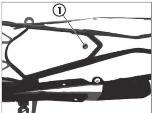
- Loosen the fastening screw 1 of the rear cover.
4
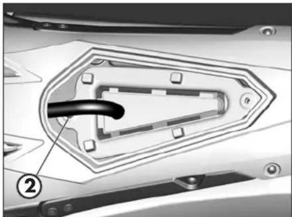
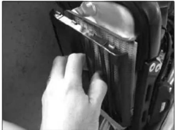
- Remove the filter frame and the filter by unscrewing the screw 2.

WARNING:
After every intervention, check that nothing has been left inside the filter box.
- Reassemble by performing the operations in reverse order.
CLEANING AIR FILTER
-
Thoroughly wash the filter with water and soap.
-
Dry the filter.
-
Wet the filter with specific oil and then remove the excess oil to prevent it from dripping.
-
If necessary also clean the interior of the filter box.

WARNING:
Do not clean the filter with gasoline or petrol.

NOTE:
If the filter is damaged, replace it immediately.
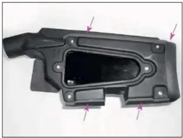
Verify the integrity of water proofing gaskets on air box shown in the picture. Change them if these are damaged.
To replace, contact authorised Betamotor customer service.

WARNING:
Never use the vehicle if the air filter is not in place. The infiltration of dust and dirt can cause damage and considerable wear.

WARNING:
After each operation check that no object is left in the filter box.
SPARK PLUG
Keeping the spark plug in good condition will reduce fuel consumption and increase engine performance.
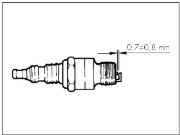
To perform the check, simply slide off the electrical connection tube and unscrew the spark plug. Examine the distance between the electrodes with a feeler. This distance should be from 0.7 ÷ 0.8 mm. If it is not, it may be corrected by bending the earth electrode.
Check as well that there are no cracks in the insulation or corroded electrodes. If so, replace immediately.
When replacing the spark plug, screw it in by hand until it stops, then tighten with a wrench.

WARNING:
Do not check while the engine is hot.
4
CHECKS AND MAINTENANCE
CARBURETOR
DRAINING THE CARBURETOR FLOAT CHAMBER
If the carburetor tank needs to be emptied, proceed as described. Perform the operation once the engine is cold.
Turn the fuel cock to OFF position (see page 20).
Place a cloth under the carburettor in order to collect the fuel that comes out.
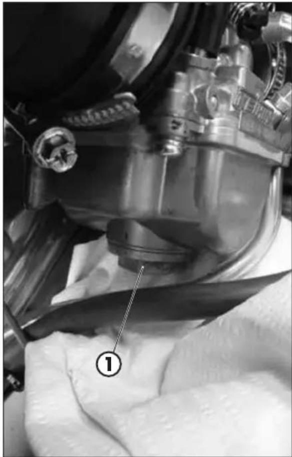
Loosen screw 1 and drain the fuel until complete emptying of the tank.
Tighten screw 1.

WARNING:
Follow action on a cold engine.

WARNING:
Fire hazard. Fuel is highly flammable.


Always stop the engine when refuelling and keep open flames and lighted cigarettes away.
Refuel in an open well ventilated area.

Immediately clean up any spilled fuel.

WARNING:
Risk of poisoning!
Fuel is poisonous liquid and a health hazard.

Wear appropriate protective clothing and protection gloves.
Fuel must not come into contact with the skin, eyes, and clothing. Do not breathe in the fuel vapours. If contact occurs with the eyes, rinse immediately with plenty of water and seek medical advice. If contact occurs with skin, immediately clean contaminated areas with soap and water. If fuel is swallowed, contact a doctor immediately. Change clothing that is contaminated with fuel.
WARNING:
Environmental pollution hazard!
The fuel must not contaminate the ground water, the ground, or the sewage system.
FLOAT LEVEL CHECK
Remove the carburetor from the vehicle after following the procedure for emptying the carburetor bowl.
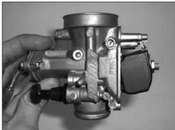
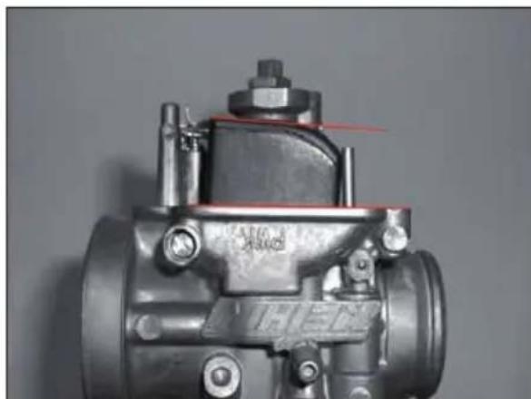
Remove the bowl and place the carburetor as in the figure.
Start turn it in anticlockwise direction and stop immediately when the float Assy closes the fuel valve needle.
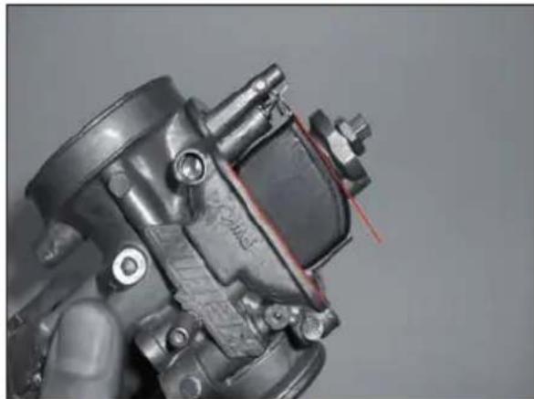
The float level is correct if the plan surface over the float assy is parallel to the float chamber division plan. See the two red lines in the picture.
ATTENTION: It's important to avoid putting carburetor in vertical position, otherwise the weight of the float assy compresses the spring into the fuel valve needle and the position will look incorrect.
Replace the bowl to the carburetor.
Reassemble the carburetor to the vehicle, making sure to tighten the metal clamps on the sleeves.
WARNING:
before starting the vehicle to check for play on the throttle (page 31).
4
FRONT BRAKE
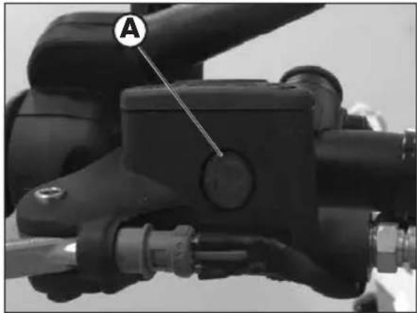
Check the level of the brake fluid through sight A. The level of the fluid should never fall below the mark in the sight.
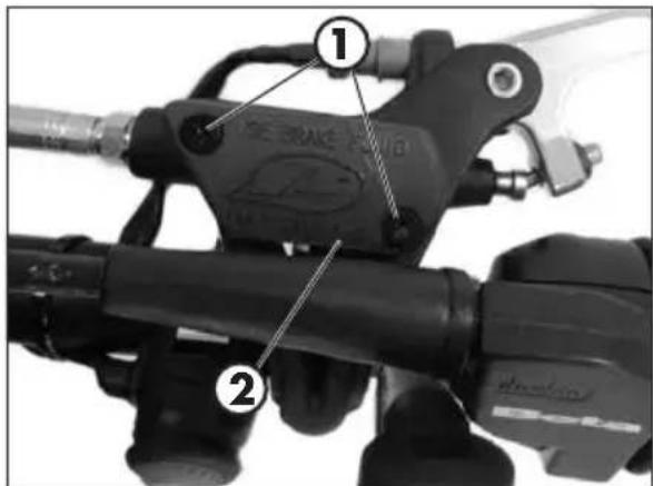
To restore the level of the brake fluid, loosen the two screws 1, lift cap 2 and add brake fluid until its level is 5mm below the upper rim of the reservoir.
Use the liquid indicated on page 16 in the "Recommended lubricants and liquids" table.

WARNING:
The clutch fluid is extremely corrosive. Take care not to spill it on the paintwork.

Wear appropriate protective clothing and protection gloves.

Keep coolant out of reach of children.

WARNING: Avoid any direct contact of the liquid with skin, eyes or clothing. If this happens:
with the eyes, rinse immediately with plenty of water and seek medical advice.
with skin, immediately clean contaminated areas with soap and water. Change clothing that is contaminated with liquid.
If liquid is swallowed, contact a doctor immediately.
BLEEDING THE FRONT BRAKE
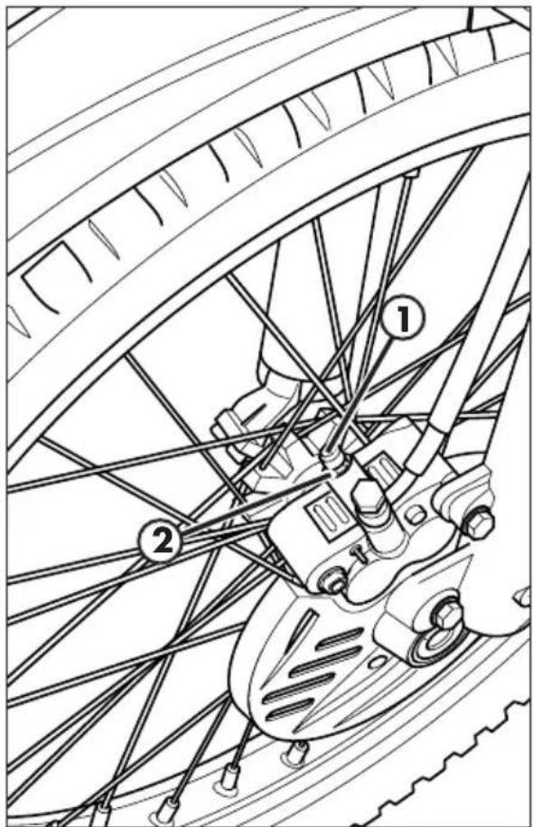
To bleed air from the front brake circuit, proceed as follows:
- Remove the rubber cap 1 from the valve 2.
- Open the sump cap.
- Insert one end of a transparent tube into a container.
- Pump with the brake lever 2/3 times and keep the lever pressed.
- Unscrew the valve and let the oil drain.
- If are still visible in the tube repeat above operation until obtaining a continuous outflow of oil within no air bubbles.
- Close the valve and release the lever.
NOTE:
During this procedure, continuously top up the brake pump thank to replace the oil that is out flowing.
- Remove the tube.
- Replace the rubber cap.
Close the oil reservoir cap.
Use the liquid indicated on page 16 in the "Recommended lubricants and liquids" table.

WARNING:
The brake fluid is extremely corrosive. Take care not to spill it on the paintwork.

Wear appropriate protective clothing and protection gloves.

Keep coolant out of reach of children.

WARNING: Avoid any direct contact of the liquid with skin, eyes or clothing. If this happens:
- with the eyes, rinse immediately with plenty of water and seek medical advice.
- with skin, immediately clean contaminated areas with soap and water. Change clothing that is contaminated with liquid.
If liquid is swallowed, contact a doctor immediately.
4
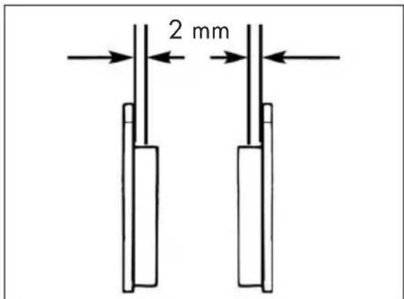
In order to verify the wear condition of front brake is enough to view the caliper from the bottom, where is possible to glimpse the brake lining tails which will have to show a brake of 2mm in thickness. If the stratum is lesser let's start replacing them.
NOTE:
Perform the check according to the times shown in the table on page 63.
To replace, contact authorised Betamotor customer service.
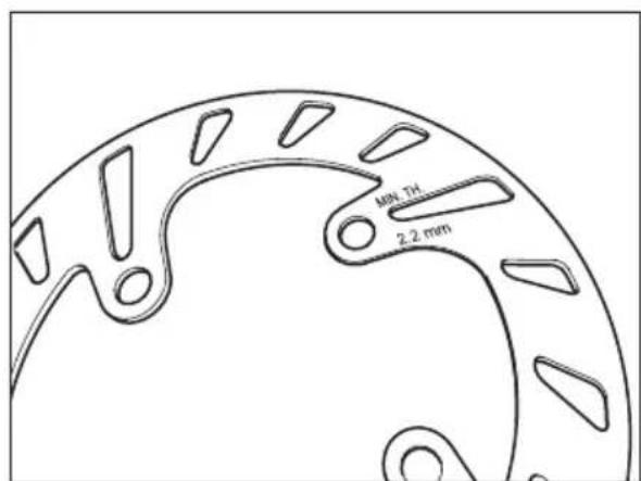
Periodically verify disc condition. In case signs of damage, veins, or deformations are present, proceed with replacement.
Verify disc thickness. The minimum thickness is engraved on the disc.
Once the limit is in proximity or has been reached, proceed with brake disc replacement.
For replacement, contact an authorised Betamotor after-sales service centre.
REAR BRAKE
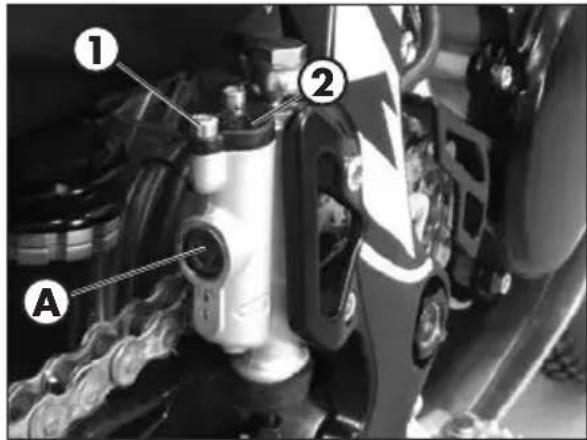
Check the level of the brake fluid through sight A. The level of the fluid should never fall below the mark in the sight.
RESTORING THE LEVEL OF THE REAR BRAKE FLUID
To restore the level of the brake fluid, loosen the two screws 1, lift cap 2 and add brake fluid until its level is 5mm below the upper rim of the reservoir.
Use the liquid indicated on page 16 in the "Recommended lubricants and liquids" table.

WARNING:
The brake fluid is extremely corrosive. Take care not to spill it on the paintwork.

Wear appropriate protective clothing and protection gloves.

Keep coolant out of reach of children.

WARNING: Avoid any direct contact of the liquid with skin, eyes or clothing. If this happens:
with the eyes, rinse immediately with plenty of water and seek medical advice.
with skin, immediately clean contaminated areas with soap and water. Change clothing that is contaminated with liquid.
If liquid is swallowed, contact a doctor immediately.
4
BLEEDING THE REAR BRAKE
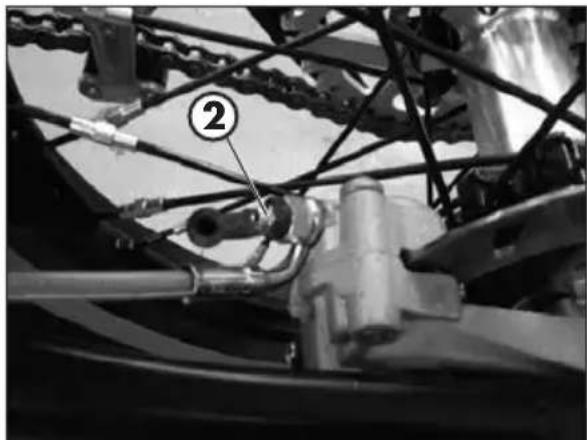
To bleed air from the rear brake circuit, proceed as follows:
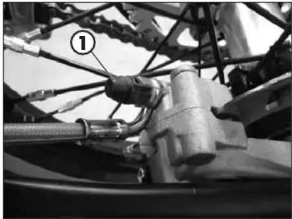
- Remove the rubber cap 1 from the valve 2.
- Open the sump cap.
- Insert one end of a transparent tube into a container.
- Place one end of a small transparent tube into the valve 2, and the other end inside a container.
- Unscrew the valve and let the oil drain.
If are still visible in the tube repeat above operation until obtaining a continuous outflow of oil within no air bubbles. - Close the valve and release the lever.
NOTE:
During this procedure, continuously top up the brake pump thank to replace the oil that is out flowing.
- Remove the tube.
- Replace the rubber cap.
Close the oil reservoir cap.
Use the liquid indicated on page 16 in the "Recommended lubricants and liquids" table.

WARNING:
The brake fluid is extremely corrosive. Take care not to spill it on the paintwork.

Wear appropriate protective clothing and protection gloves.

Keep coolant out of reach of children.

WARNING: Avoid any direct contact of the liquid with skin, eyes or clothing. If this happens:
- with the eyes, rinse immediately with plenty of water and seek medical advice.
- with skin, immediately clean contaminated areas with soap and water. Change clothing that is contaminated with liquid.
If liquid is swallowed, contact a doctor immediately.
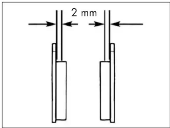
In order to verify the wear condition of rear brake is enough to view the caliper from the back side, where is possible to glimpse the brake lining tails which will have to show a brake of 2mm in thickness. If the stratum is lesser let's start replacing them.
NOTE:
Perform the check according to the times shown in the table on page 63.
To replace, contact authorised Betamotor customer service.
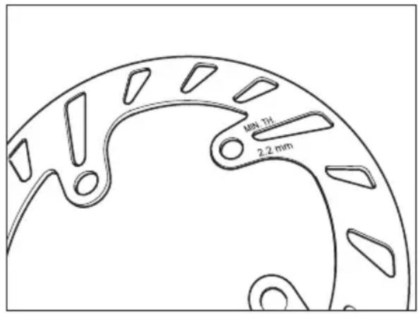
Periodically verify disc condition. In case signs of damage, veins, or deformations are present, proceed with replacement.
Verify disc thickness. The minimum thickness is engraved on the disc.
Once the limit is in proximity or has been reached, proceed with brake disc replacement.
For replacement, contact an authorised Betamotor after-sales service centre.
4
CLUTCH CONTROL CHECK OIL LEVEL
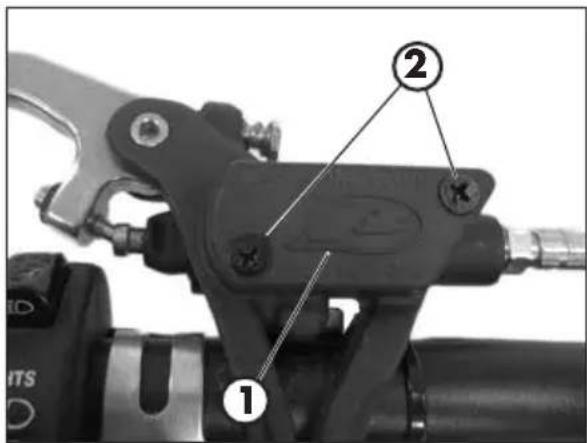
To check the oil level in the clutch pump, first remove cover 1.
Remove the two screws 2 and take off cover 1 together with the rubber bellows. With the clutch pump in a horizontal position, the level of the oil should be 5mm below the upper rim.
Use the liquid indicated on page 16 in the "Recommended lubricants and liquids" table.

WARNING:
The brake fluid is extremely corrosive. Take care not to spill it on the paintwork.

Wear appropriate protective clothing and protection gloves.

Keep coolant out of reach of children.

WARNING: Avoid any direct contact of the liquid with skin, eyes or clothing. If this happens:
with the eyes, rinse immediately with plenty of water and seek medical advice.
with skin, immediately clean contaminated areas with soap and water. Change clothing that is contaminated with liquid.
If liquid is swallowed, contact a doctor immediately.
BLEEDING CLUTCH CONTROL
- Remove the rubber cap 1 from the valve 2.
- Open the sump cap.
- Insert one end of a transparent tube into a container.
- Pump with the brake lever 2/3 times and keep the lever pressed.
- Unscrew the valve and let the oil drain.
- If are still visible in the tube repeat above operation until obtaining a continuous outflow of oil within no air bubbles.
- Close the valve and release the lever.
NOTE:
During this procedure, continuously top up the brake pump thank to replace the oil that is out flowing.
- Remove the tube.
- Replace the rubber cap.
Use the liquid indicated on page 16 in the "Recommended lubricants and liquids" table.
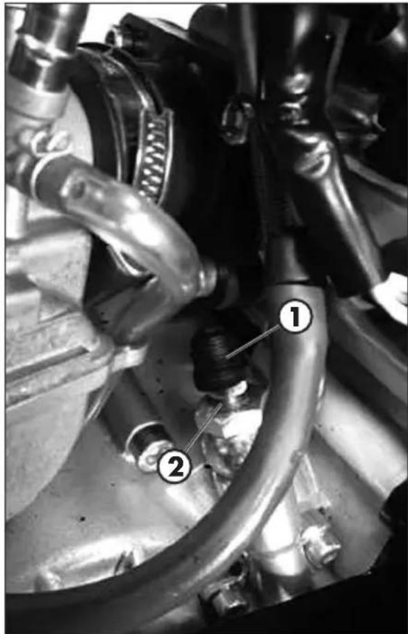

WARNING:
The clutch fluid is extremely corrosive. Take care not to spill it on the paintwork.

Wear appropriate protective clothing and protection gloves.

Keep coolant out of reach of children.

WARNING: Avoid any direct contact of the liquid with skin, eyes or clothing. If this happens:
- with the eyes, rinse immediately with plenty of water and seek medical advice.
- with skin, immediately clean contaminated areas with soap and water. Change clothing that is contaminated with liquid.
If liquid is swallowed, contact a doctor immediately.
4
CHECKS AND MAINTENANCE

CHECK OF STEERING GEAR
Periodically check the play in the steering sleeve by moving the fork back and forth as shown in the figure. Whenever you feel play, adjust as described below:
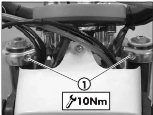
Loosen the screws 1.

Loosen the screw 2.
Take up the play by means of nut 3.
Tighten the screws to the specified torque values.
OIL FORK
The procedure for changing the oil in the forks is provided only for information. We recommend having the operation performed by a BETAMOTOR authorized workshop.
REMOVING LEGS
To replace, proceed as follows:
Position the vehicle on the central bike stand.
Remove the front wheel.
Remove the mudguard, the brake caliper and brake disc cover.
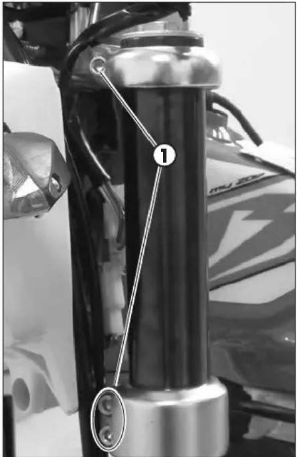
Loosen the screws! and pull off the stems.
OIL REPLACEMENT RIGHT LEG
Unscrew upper plug 2.
Unscrew fixing lock nut and take off the plug.
Unscrew the fixing screw of the cartridge positioned under the fork leg, and extract the cartridge.
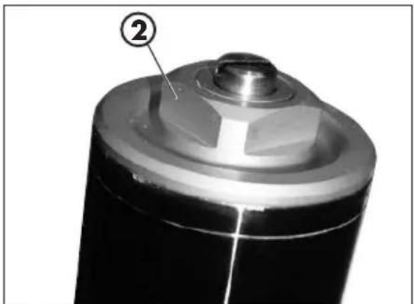
Empty the fork leg and the cartridge, draining all the oil inside.
Reassemble the cartridge on the fork leg tightening the fixing screw, then refill oil in the cartridge.
Pour in the quantity of liquid indicated on page 11.
Use the liquid indicated on page 16 in the "Recommended lubricants and liquids" table.
Reassemble the plug on the rod, tighten the lock nut and, extending the fork leg.
OIL REPLACEMENT LEFT LEG
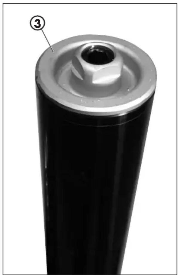
Unscrew upper plug 3.
Remove the spring and totally empty the oil.
Pour in the quantity of liquid indicated on page 11.
Reassemble the spring and extend fork leg.
Apply and tighten cap 3.
LEGS ASSEMBLY AND PARTS
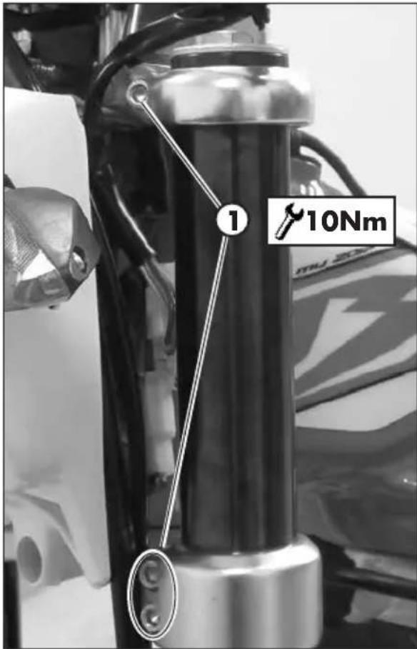
Apply the legs to the vehicle and tighten the screws 1 to the torque indicated.
ATTENTION: Tightening of the screws should be carried out by adjusting the torque wrench to the stability torque with repeated tightening until stability torque has been achieved.
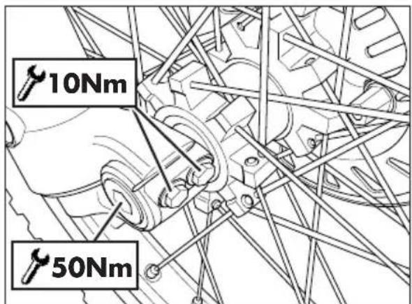
Grease the wheel bolt.
Apply wheel and wheel bolt.
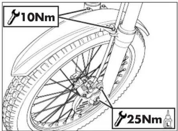
Apply brake caliper, disc cover and fender.
Tighten to the torque indicated.

ATTENTION: Tightening of the screws should be carried out by adjusting the torque wrench to the stability torque with repeated tightening until stability torque has been achieved.
Place the vehicle on the ground.
Compress and release the fork 3-4 times.
Tighten the wheel bolt and the screws of the foot.

ATTENTION: Tightening of the screws should be carried out by adjusting the torque wrench to the stability torque with repeated tightening until stability torque has been achieved.
4
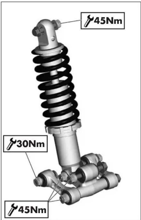
LINKAGE REAR SUSPENSION
To guarantee an optimal operation and the longest lifetime of the progressive linkage of the rear suspension, it is recommended to check after every race/run the correct tightening of the bolt.
Verify that the result of the suspension bolts to specified torque.
To access the upper fixing, remove the entire mudguard group (page 68).
NOTE: It is recommended not to wash with water jets at high pressure in the zone of the linkage.
Perform the check according to the times indicated in the table on page 63.
To verify device, contact authorised Betamotor customer service.
TYRES
Only fit tyres approved by BETAMOTOR.
Unsuitable tyres can adversely affect the road holding of the vehicle.
- To protect your safety, immediately replace any damaged tyres.
- Slick tyres adversely affect the road holding of the vehicle, especially on wet roads and in off-road riding.
Insufficient pressure results in abnormal wear and overheating of the tyres.
The front and rear tyres must have the same tread design. - Always measure the inflating pressures when the tyres are cold.
- Keep the tyre pressures within the prescribed range.
CHAIN
Checking the drive chain periodically to ensure longer chain life. Always keep it lubricated and clean of deposited dirt.
Take special care in preventing the lubricant from coming into contact with the rear tyre or brake disc, otherwise the tyre grip and the action of the brake would be greatly reduced, making it very difficult to control the vehicle.
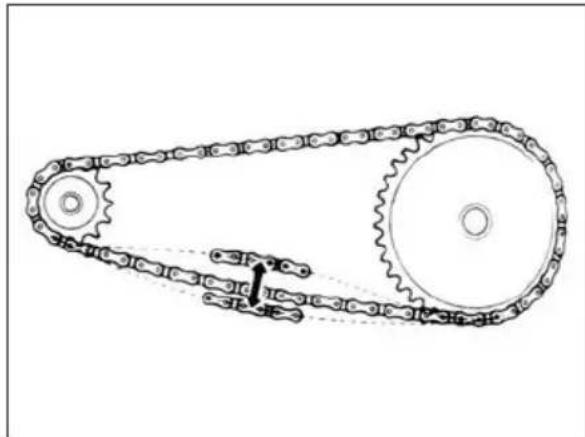
CHECK AND ADJUST TIGHTENING CHAIN
Position the vehicle on the central bike stand.
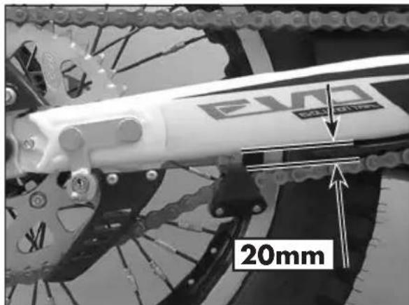
If the distance between chain and swingarm is less than 20mm proceed with adjustment.
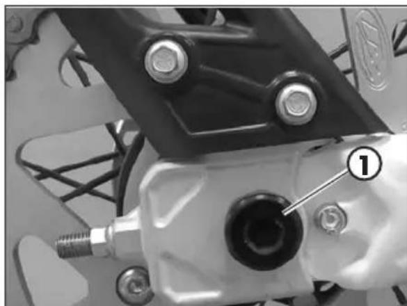
Loosen the pin 1.
4
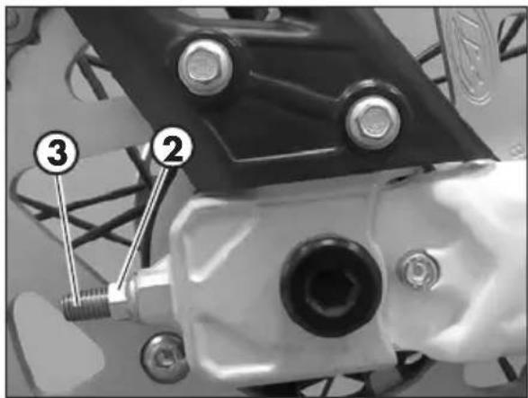
Loosen counternut 2 (one per side) and adjust register 3 until the desired tension is obtained.
CHECKS AND MAINTENANCE
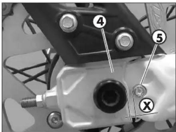
Measure distance X between number plate holder support 4 and anvil 5.
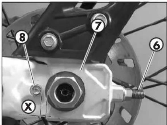
Measure distance x between number plate holder support 4 and anvil 5.
Ensure the distance between chain and swingarm is that recommended.
If the distance between chain and swingarm is not that recommended pro ceed to readjustment.
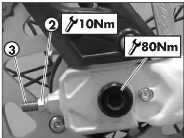
After completing adjustment, keep register 3 locked and tighten counter-nut 2 (on each side) to the specified torque.
Tighten the pin to the torque indicated.
HEADLIGHT
Keep the headlight glass clean at all times (page 61).
REPLACING THE HEADLIGHT BULBS
Dismantle the headlight mask removing the two retaining screws 1 indicated in the figure.
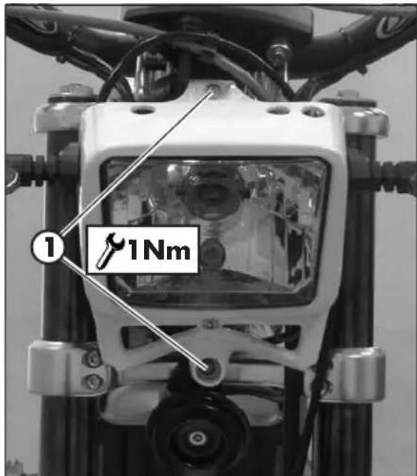
To replace the high/low beam bulb, proceed as follows: lift rubber cap 2.
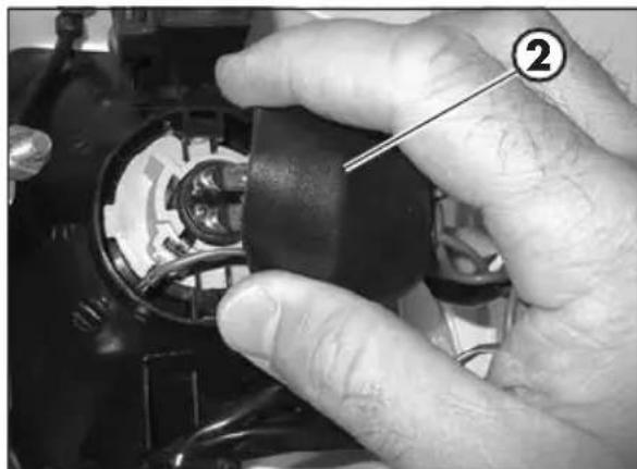
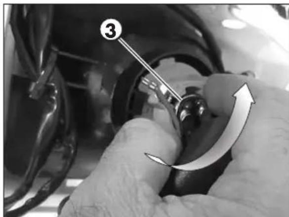
Turn bulb holder 3 anticlockwise and remove the bulb holder from the headlight body.
Turn the bulb counterclockwise with respect to the bulb holder. Replace the bulb.
To reassemble the bulb and bulb holder, proceed in reverse order with respect to disassembly.
4
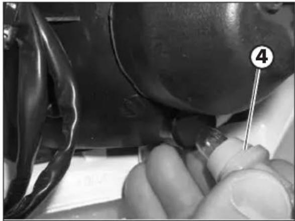
To replace the daylight bulb, proceed as follows.
Pull the whole bulb holder 4.
Take the bulb and remove it from the bulb holder.
Replace the bulb.
To reassemble the bulb and bulb holder, proceed in reverse order with respect to disassembly.
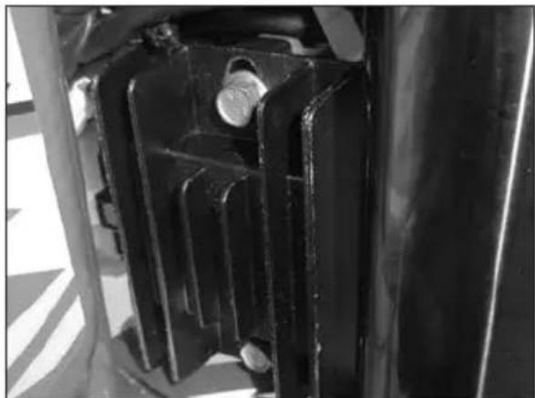
To replace the headlight group proceed in reverse order with respect to the above instructions paying attention to the instrument and regulator support fixing devices.
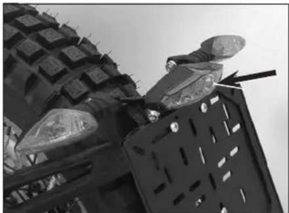
REAR TAIL LIGHT
Keep the tail light glass clean at all times (see page 61).
The LED tail light is sealed. In the case of burnout of one or more LEDs it is necessary to replace the entire group.
To replace, contact authorised Betamotor customer service.
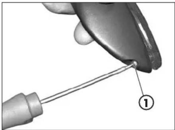
TURN INDICATORS
To reach the bulb, remove the glass cover by loosening screw 1.
Remove the bulb from the connectors and carry out replacement.
CLEANING THE VEHICLE
GENERAL PRECAUTIONS

WARNING: Do not clean your vehicle with a high-pressure device with a strong jet of water. Excessive pressure can reach electrical components, connectors, flexible cables, bearings, etc and can damage or destroy them.

WARNING: Wash motorbikes frequently with cold water that are used near the sea (salty air) and on roads subject to salt spreading in winter. Cover with a film of oil or silicone spray unpainted parts and the most exposed parts such as wheels, forks and swingarm. Do not treat rubber parts and brakes.
When cleaning, avoid direct exposure to sunlight.
Close off the exhaust system to prevent water from entering.

Avoid directing the jet of water onto the air filter box cover and the carburettor.
WASHING MODE
Use water jet to soften the dirt and mud accumulated on the paintwork, then remove them with a soft bodywork sponge soaked in water and shampoo. Subsequently rinse well with water, and dry with air and cloth or suede leather.
Detergents pollute water. Always wash the vehicle in areas equipped for collection and purification of the washing liquids.
AFTER WASHING
Proceed to the emptying of the filter box using the appropriate ventilation and drying.
After cleaning, ride a short distance until the engine reaches operating temperature.


WARNING: braking effect is reduced with wet brakes. Operate the brakes cautiously to allow them to dry.
Push back the handlebar control covers, so that water can evaporate.
When the bike is completely dry and cooled down, lubricate all moving parts.
Treat all plastic and painted components with non-aggressive detergents or products that are specific for the care of the motorcycle.
To prevent malfunction of the electrical system, treat electric contacts and switches with electrical contact spray.

ATTENTION: any oxidation of electrical contacts may result in serious malfunctioning.
PROLONGED INACTIVITY
A few simple operations should be performed to keep the vehicle in good condition whenever it is to remain inactive for a long period (e.g. during the winter):
- Thoroughly clean the vehicle.
- Reduce the tyre pressures by approximately 30 percent, and if possible raise the tyres off the ground.
- Remove the spark plug and pour a few drops of engine oil into the spark plug hole. Make the engine turn a few times by operating the kick-start (where available) and then replace the spark plug.
- Cover the unpainted parts, excepting the brakes and the rubber parts, with a film of oil or spray silicone.
- Protect the vehicle with a dust cover.
- Drain the carburetor tank as described at page 42.
AFTER PROLONGED INACTIVITY
- Restore the tyre inflating pressures.
- Check the tightening of all the screws having an important mechanical function.
SCHEDUED MAINTENANCE VEHICLE
| Vehicle | ||||||||||||||||||||||||||||||||||||||||||||||||||||||||||||||||||||||||||||||||||||||||||||||||||||||||||||||||||||||||||||||||||||||||||||||||||||||||||||||||||||||||||||||||||||||||||||||||||||||||||||||||||||||||||||||||||||||||||||||||||||||||||||||||||||||||||||||||||||||||||||||||||||||||||||||||||||||||||||||||||||||||||||||||||||||||||||||||||||||||||||||||||||||||||||||||||||||||||||||||||||||||||||||||||||||||||||||||||||||||||||||||||||||||||||||||||||||||||||||||||||||||||||||||||||
| Spark plug | End of running-in 5 hours | |||||||||||||||||||||||||||||||||||||||||||||||||||||||||||||||||||||||||||||||||||||||||||||||||||||||||||||||||||||||||||||||||||||||||||||||||||||||||||||||||||||||||||||||||||||||||||||||||||||||||||||||||||||||||||||||||||||||||||||||||||||||||||||||||||||||||||||||||||||||||||||||||||||||||||||||||||||||||||||||||||||||||||||||||||||||||||||||||||||||||||||||||||||||||||||||||||||||||||||||||||||||||||||||||||||||||||||||||||||||||||||||||||||||||||||||||||||||||||||||||||||||||||||||||||
| Clutch | PS | 55 | Cyc160 | 50km | ||||||||||||||||||||||||||||||||||||||||||||||||||||||||||||||||||||||||||||||||||||||||||||||||||||||||||||||||||||||||||||||||||||||||||||||||||||||||||||||||||||||||||||||||||||||||||||||||||||||||||||||||||||||||||||||||||||||||||||||||||||||||||||||||||||||||||||||||||||||||||||||||||||||||||||||||||||||||||||||||||||||||||||||||||||||||||||||||||||||||||||||||||||||||||||||||||||||||||||||||||||||||||||||||||||||||||||||||||||||||||||||||||||||||||||||||||||||||||||||||||||||||||||||||
Key
C Check (Clean, adjust, lubricate, replace as necessary)
S Replace/renew
R Adjust
P Clean
T Tighten
4 TIGHTENING TORQUE OVERVIEW
Here below is an overview of the tightening torque of all pieces subject to adjustment or maintenance:
| Forecarriage | ||
| Tightening torque [Nm] Threadlock | ||
| Wheel pin | 50 | |
| Fork foots - wheel pin | 10* | |
| Brake caliper - Fork | 25 | M |
| Steering head base - fork legs | 10* | |
| Steering head - fork legs | 10 | |
| Stem pin on steering head | 10 | |
| Upper handlebar u-bolt 20 | ||
| Rear axle | ||
| Tightening torque [Nm] Th | readlock | |
| Wheel pin | 80 | |
| Rear shock absorber - frame | 45 | |
| Rear shock absorber - rocker arm | 45 | |
| Connecting rod - frame | 30 | |
| Connecting rod - rocker arm | 45 | |
| Rocker arm - swinging arm | 45 | |
| Engine | ||
| Tightening torque [Nm] Th | readlock | |
| Gearbox oil drain plug 10 | ||
| Bleeding screw cooling system 10 | ||
| Superstructures | ||
| Tightening torque [Nm] | Grease | |
| Front mudguard 10 | ||
| Rear mudguard 2,5 G | ||
| Headlamps | ||
| Tightening torque [Nm] Threadlock | ||
| Headlight mask 1 | ||
M Medium strength threadlock

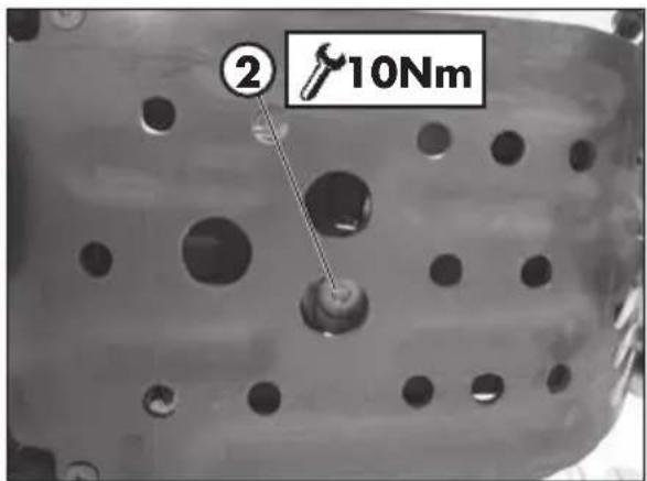
WARNING: Tijtari
Tightening of the screws should be carried out by adjusting the torque wrench to the stability torque with repeated tightening until stability torque has been achieved.
CHAPTER 5 REMOVING AND INSTALLING SUPERSTRUCTURES
CONTENTS
Removing and installing saddle-mudguard assembly. 68
5
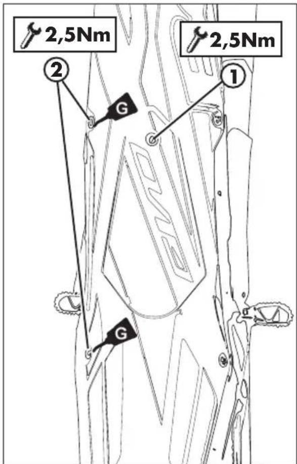
REMOVING AND INSTALLING SADDLE-MUDGUARD ASSEMBLY
Remove screws 1 and 2 (two per side). Remove the mudguard.
At the end refit the screws 1 and 2.
Tighten to the torque indicated.
CHAPTER 6 TROUBLESHOOTING
CONTENTS
Troubleshooting 70
Alphabetical index 71
| PROBLEM CAUSE | SE REMEDY | |
| The engine turns over but will not start | Fuel valve in OFF position | Move the fuel valve in ON or RES position |
| Dirty carburettor jets Contact authorised | Seted Betamotor customer service | |
| Spark plug dirty Clean or replace the spark plug | ||
| Spark gap wrongly adjusted Restore | the spark gap (page 41) | |
| Fault in the ignition system Contact | authorised Betamotor customer service | |
| The power delivered by the engine is insufficient | Tank vent obstructed Check the tank | vent |
| Fuel system dirty Contact authorised | Betamotor customer service | |
| Air filter dirty Clean the air filter | ||
| Defective ignition system Contact | authorised Betamotor customer service | |
| The motor stops or splutters | Lack of fuel Move the fuel cock to RES | |
| Refuel | ||
| Poor carburettor seal Make sure that the sleeve between carburetor and engine is intact | ||
| Loose or oxidized connector or ignition coil | Check the connector. Clean and treat with specific spray | |
| Engine overheats (liquid flows out/vapor from the vent radiator) | Radiator grill blocked Remove and clean the grill (page 39) | |
| Radiator (air side) blocked Clean the radiator | ||
| Forced ventilation absent | Check that the cooling fan is working correctly | |
| Silencer partly clogged | Contact authorised Betamotor customer service | |
| Carburation too lean | Contact authorised Betamotor customer service | |
| Front braking poor | Brake pads worn | Contact authorised Betamotor customer service |
| Air or humidity in the hydraulic circuit | Contact authorised Betamotor customer service | |
| Rear braking poor | Brake pads worn | Contact authorised Betamotor customer service |
| Air or humidity in the hydraulic circuit | Contact authorised Betamotor customer service |
ALPHABETICAL INDEX
Accelerator 31
Adjusting fork 32
Adjustment of gas clearance. 31
Air filter 39
Breaking in. 26
Carburetor 42
Chain 57
Check of steering gear. 52
Checks before and after use 26
Cleaning the vehicle 61
Clutch 30
Clutch control 50
Coolant 37
Digital rpm indicator operating instructions. 22
Electrical system 14
Engine shut-down 28
Familiarizing with the vehicle. 9
Front Brake 44
Fuelling 27
Gear oil 36
Handlebar adjustment 31
Headlight 59
Headlight adjustment 34
Key to symbols. 30
Key to symbols. 36
Main parts 18
Oil fork. 53
Operating instructions 5
Prolonged inactivity 62
Rear brake 47
Rear tail light 60
Recommended lubricants and liquids 16
Removing and installing saddle-mudguard assembly. 68
Riding safety 6
Scheduled maintenance vehicle 63
Shock absorber 32
Spark plug 41
Specifications 10
Startup 28
Suspension adjustment according to the motorcyclist's weight 34
Symbols 5
Tightening torque overview 64
Troubleshooting 70
Turn indicators 60
Tyres. 56
Vehicle identification data 8

EVO 2T EUROPE
Approvalnment carburant 27
Demarrage moteur 28
Arrêt du moteur 28
CHAP. 3 RÉGLAGES 29
Legendesymboles 30
Embrayage 30
Réglagejeugaz 31
Accélérateur 31
ESTÁ PROHIBIDO FUMAR
ESTA PROHIBIDO EL USO DEL TELEFONO MOVIL
PELIGRO DEBIDO A LA PRESENCIA DE SUSTANCIAS CORROSIVAS
HFDST. 1 ALGEMENE INFORMATIE
HFDST. 1 ALGEMENE INFORMATIE
INHOUD THEMA'S
Framenummer 8
Motoridentification 8
INSTRUCTIES WERKING DIGITALE SNELHEIDSMETER HOOFDONDERDELEN
Tijd