
RC1590 - Receiver ROTEL - Free user manual and instructions
Find the device manual for free RC1590 ROTEL in PDF.
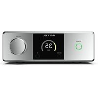
| Product type | Stereo control amplifier / Receiver |
| Brand | Rotel |
| Model | RC-1590 |
| Height | 132,6 mm (3U) |
| Net weight | 9,2 kg |
| Power supply | 120 V / 60 Hz (US) or 230 V / 50 Hz (Europe) |
| Power consumption | 45 W (operating), < 0,5 W (standby) |
| Total harmonic distortion | < 0,002 % (20 Hz - 20 kHz) |
| Signal-to-noise ratio (line inputs) | 112 dB (IHF A weighted) |
| Analog inputs | Phono (MM), CD, Tuner, Aux (RCA), 1 pair XLR balanced |
| Digital inputs | 3 coaxial, 3 optical, 1 USB PC, 1 USB Apple (front panel) |
| Wireless input | Bluetooth with APTX codec |
| Analog outputs | 2 pairs RCA preamp, 2 pairs XLR balanced, 1 line output, 1 headphone output (3.5 mm jack), 2 mono subwoofer outputs |
| Digital output | 1 coaxial (unprocessed PCM) |
| Supported audio formats | PCM up to 384 kHz/32 bit (USB Class 2.0), DSD64/128, Bluetooth APTX |
| Additional features | Tone control (bass/treble) with bypass, balance, brightness adjustment, 12 V trigger, Rotel Link, RS232, network port (firmware update) |
| Remote control | Infrared RR-AX100 (AA batteries included) |
| Maintenance | Clean with a dry cloth or vacuum; do not use liquids |
| Safety | Double insulation; do not expose to moisture; no user-serviceable parts |
| Included accessories | Driver CD, USB cable, Rotel Link cable, remote control, batteries |
Frequently Asked Questions - RC1590 ROTEL
User questions about RC1590 ROTEL
0 question about this device. Answer the ones you know or ask your own.
Ask a new question about this device
Download the instructions for your Receiver in PDF format for free! Find your manual RC1590 - ROTEL and take your electronic device back in hand. On this page are published all the documents necessary for the use of your device. RC1590 by ROTEL.
USER MANUAL RC1590 ROTEL
Important Safety Instructions
Notice
The RS232 connection should be handled by authorized persons only.
WARNING: There are no user serviceable parts inside. Refer all servicing to qualified service personnel.
WARNING: To reduce the risk of fire or electric shock, do not expose the unit to moisture or water. Do not expose the unit to dripping or splashing. Do not place objects filled with liquids, such as vases, on the unit. Do not allow foreign objects to get into the enclosure. If the unit is exposed to moisture, or a foreign object gets into the enclosure, immediately disconnect the power cord from the wall. Take the unit to a qualified service person for inspection and necessary repairs.
Read these instructions.
Keep these instructions.
Heed all warnings.
Follow all instructions.
Do not use this apparatus near water.
Clean only with dry cloth.
Do not block any ventilation openings. Install in accordance with the manufacturer's instructions.
Do not install near any heat sources such as radiators, heat registers, stoves, or other apparatus (including amplifiers) that produce heat. Do not defeat the safety purpose of the polarized or grounding-type plug. A polarized plug has two blades with one wider than the other.
A grounding type plug has two blades and a third grounding prong.
The wide blade or the third prong are provided for your safety. If the provided plug does not fit into your outlet, consult an electrician for replacement of the obsolete outlet.
Protect the power cord from being walked on or pinched particularly at plugs, convenience receptacles, and the point where they exit from the apparatus.
Only use attachments/accessories specified by the manufacturer.
Use only with the cart, stand, tripod, bracket, or table specified by the manufacturer, or sold with the apparatus. When a cart is used, use caution when moving the cart/ apparatus combination to avoid injury from tip-over.

Unplug this apparatus during lightning storms or when unused for long periods of time.
Refer all servicing to qualified service personnel. Servicing is required when the apparatus has been damaged in any way, such as power supply cord or plug is damaged, liquid has been spilled or objects have fallen into the apparatus, the apparatus has been exposed to rain or moisture, does not operate normally, or has been dropped.
The apparatus should be used in non tropical climate.
WARNING: The rear panel power cord connector is the mains power disconnect device. The device must be located in an open area that allows access to the cord connector.
The unit must be connected to a power supply only of the type and voltage specified on the rear panel. (USA: 120 V/60Hz, EC: 230V/50Hz)
Connect the component to the power outlet only with the supplied power supply cable or an exact equivalent. Do not modify the supplied cable. Do not use extension cords.
The mains plug is the disconnect of the unit. In order to completely disconnect the unit from the supply mains, remove the main plug from the unit and the AC power outlet. This is the only way to completely remove mains power from the unit.
The batteries in the remote control should not be exposed to excessive temperature such as sunshine, fire or other heat sources. Batteries should be recycled or disposed as per state and local guidelines.
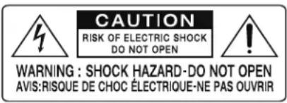
| APPLICABLE FOR USA, CANADA OR WHERE APPROVED FOR THE USAGE |
| CAUTION: TO PREVENT ELECTRIC SHOCK, MATCH WIDE BLADE OF PLUG TO WIDE SLOT. INSERT FULLY. |
| ATTENTION: POUR EVITER LES CHOCS ELECTRIQUES, INTRODUIRE LA LAME LA PLUS LARGE DE LA FICHE DANS LA BORNE CORRESPONDANTE DE LA PRISE ET POUSSER JUSQU AU FOND. |

Rotel products are designed to comply with international directives on the Restriction of Hazardous Substances (RoHS) in electrical and electronic equipment and the disposal of Waste Electrical and Electronic Equipment (WEEE). The crossed wheelie bin symbol indicates compliance and that the products must be appropriately recycled or processed in accordance with these directives.

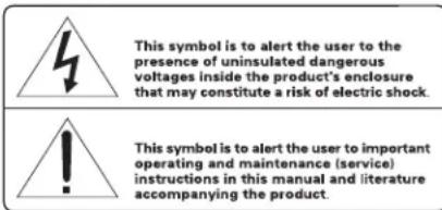
This symbol means that this unit is double insulated. An earth connection is not required.
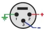
Pin Assignments
Balanced Audio (3 pole XLR):
Pin 1: Ground / Screen
Pin 2: In phase / +ve / Hot
Pin 3: Out of phase / -ve / Cold

Figure 1: Controls and Connections Commandes et Branchements Bedienelemente und Anschlüsse Controles y Conexiones
Bedieningselementen en aansluitingen
Controlli e connessioni
Kontroller och anslutningar
Органы управления и разъемы
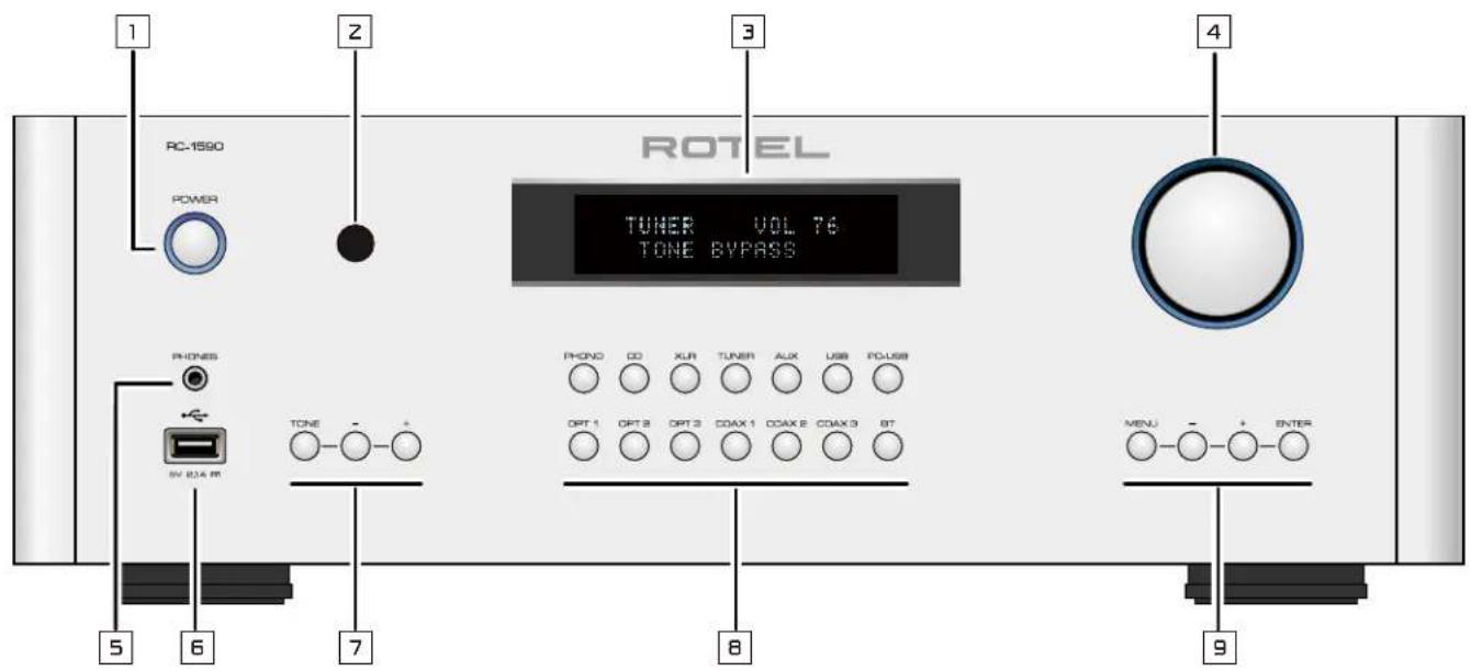
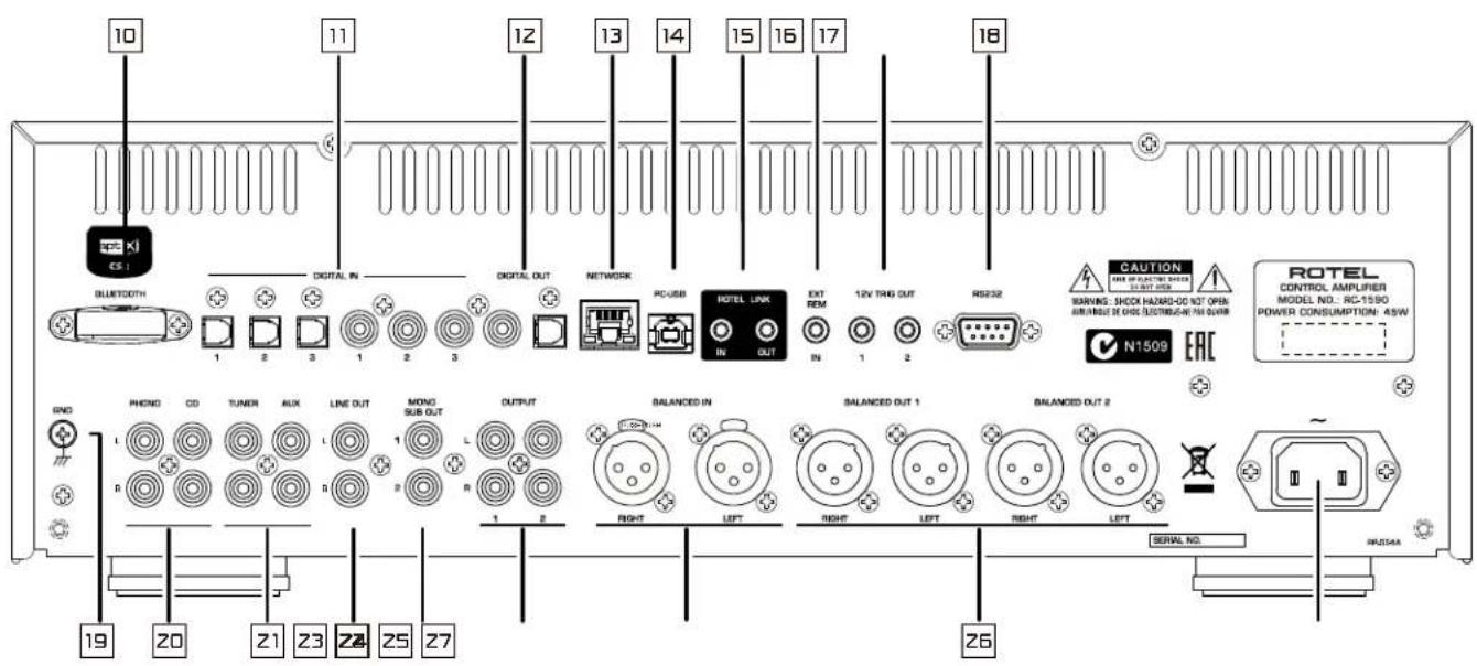
Figure 2: RR-AX100 Remote Control
Télécommande infrarouge RR-AX100
Fernbedienung RR-AX100
Mando a Distancia RR-AX100
Afstandsbediening RR-AX100
Telecomando RR-AX100
RR-AX100 fjärrkontroll
Пульт ДУ RR-AX100
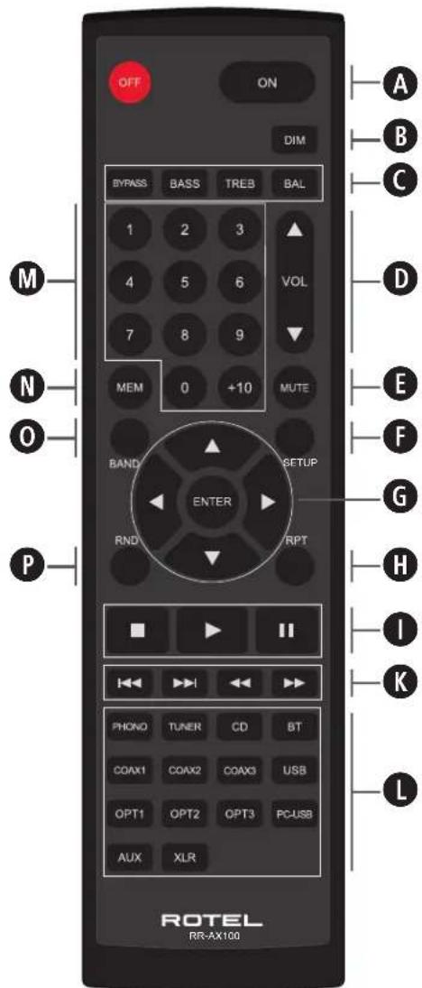
Figure 3: Analog Input and Output Connections
Branchements des entrées et sorties analogiques
Analoge Ein- und Ausgangsanschlüsse
Entradas y Salidas Analógicas
Analoge ingangen en uitgangen
Collegamenti ingressi ed uscite analogici
Anslutningar för analoga in- och utgångar
Аналоговые входы и выходы
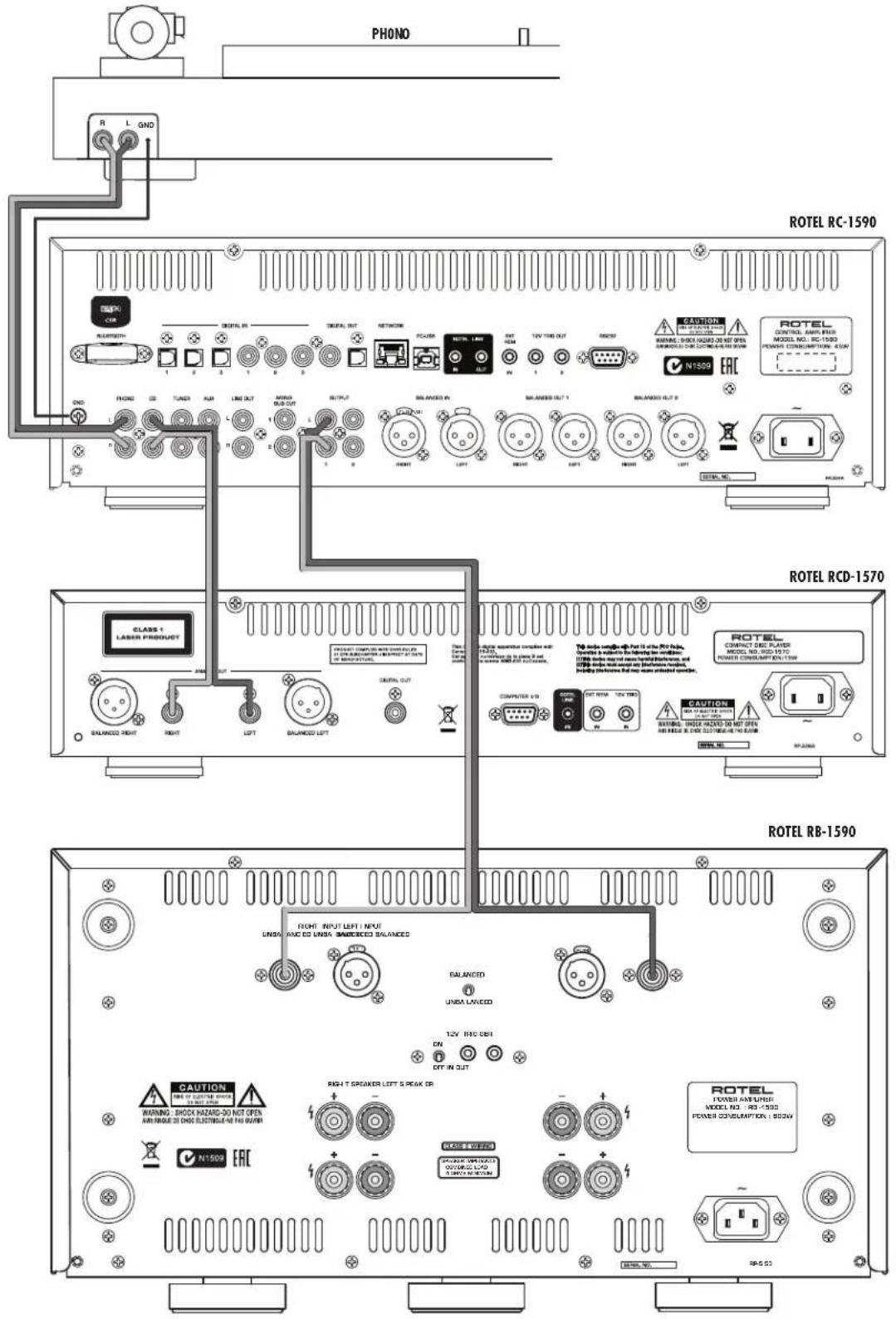
Figure 4: Balanced (XLR) Input and Output Connections
Branchements des entrées et sorties symétriques (XLR)
Symmetrische Ein- und Ausgangsanschlüsse (XLR)
Entradas y Salidas Balanceadas (XLR)
Gebalanceerde ingangen (XLR) en uitgangen
Collegamenti ingressi ed uscite bilanciati (XLR)
Balanserade in- och utgångar (XLR)
Балансные (XLR) входы и выходы
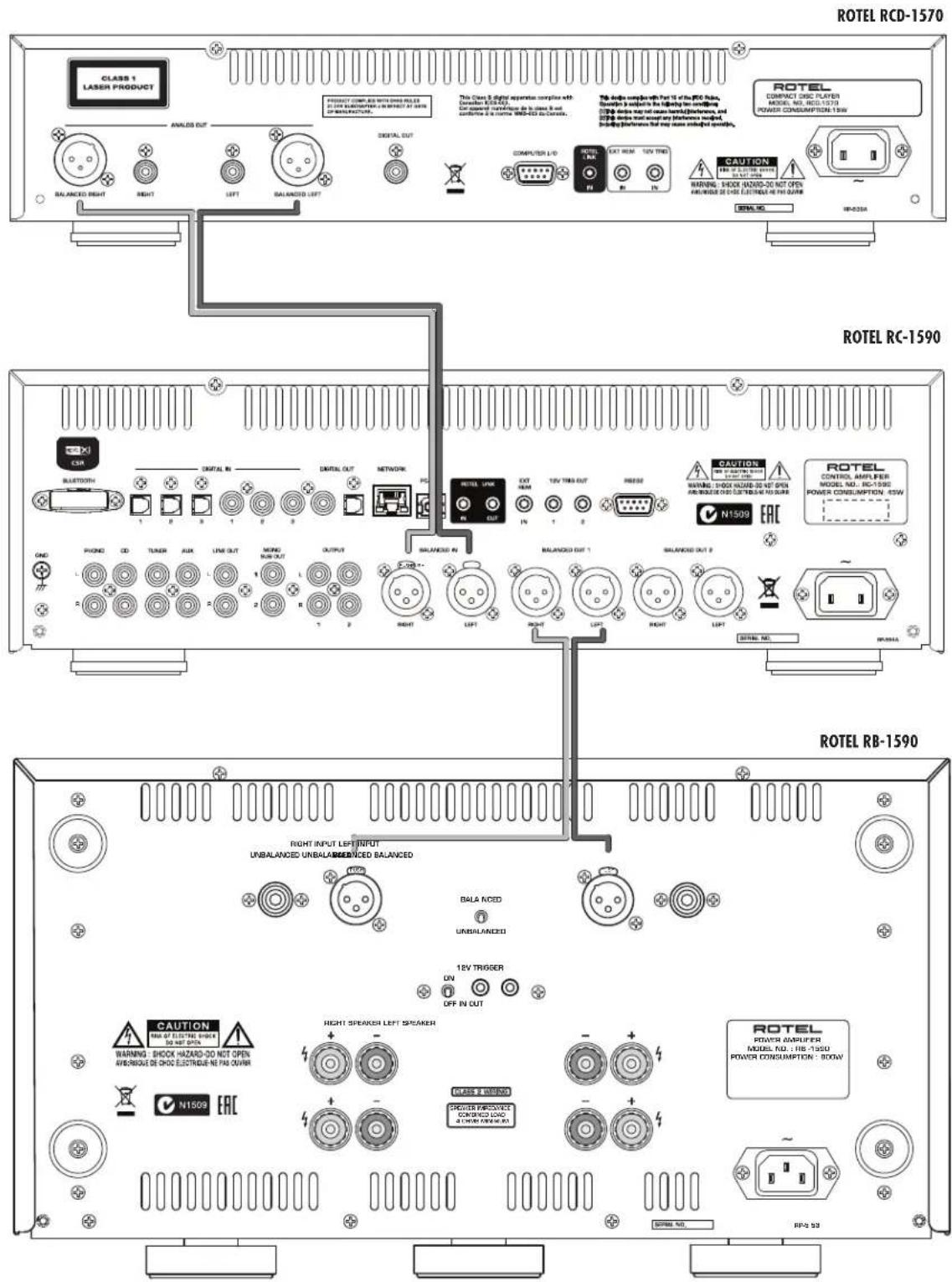
Figure 5: Digital Inputs and 12V Trigger Output
Entrées numériques et Branchements des sorties trigger 12 V
Digitaleingänge und 12V TRIG-Ausgang
Entradas Digitales y Salida para Señal de Disparo de 12V
Digitale ingangen en 12V trigger-uitgang
Collegamenti ingressi digitali e segnali Trigger 12 V
Anslutningar för digitala ingångar och 12-volts styrsignaler
Цифровые входы и 12-В триггерный выход
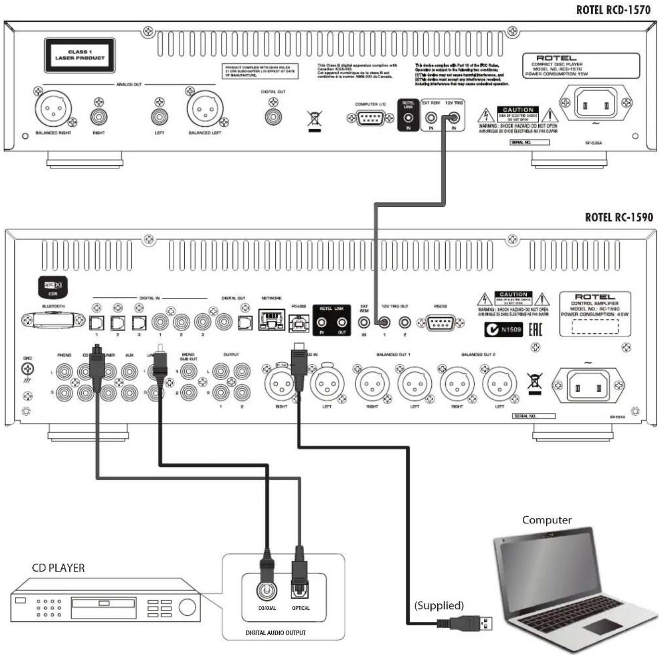
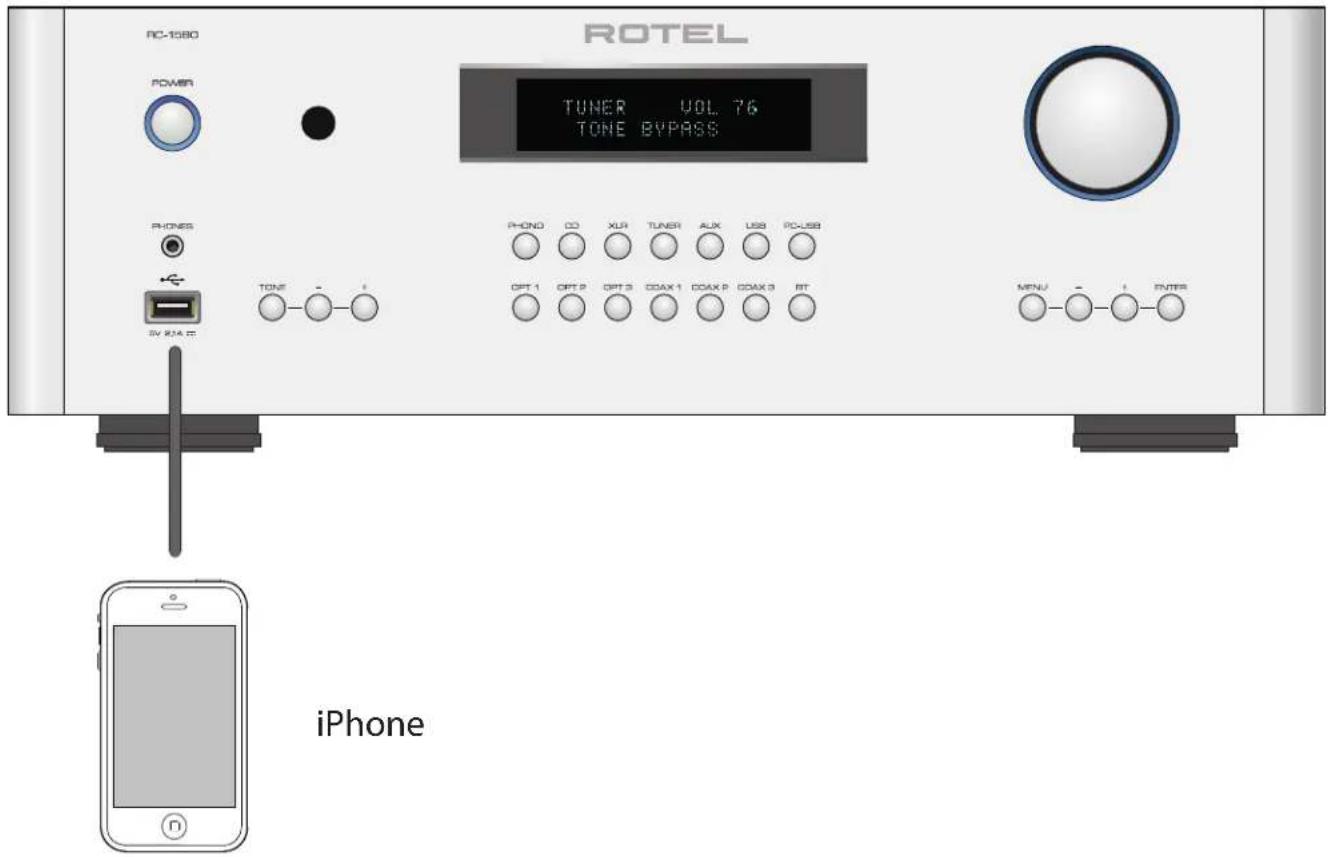
Figure 6: Front USB Input
Entrée USB en face avant
Frontseitiger USB-Eingang
Entrada USB Frontal
USB-ingang op het voorpaneel
Ingresso USB frontale
USB-port på fronten
USB вход на передней панели
Important Notes
When making connections be sure to:
√ Turn off all the components in the system before hooking up any components, including loudspeakers.
√ Turn off all components in the system before changing any of the connections to the system.
It is also recommended that you:
√ Turn the volume control of the amplifier all the way down before the amplifier is turned on or off.
Remarques importantes
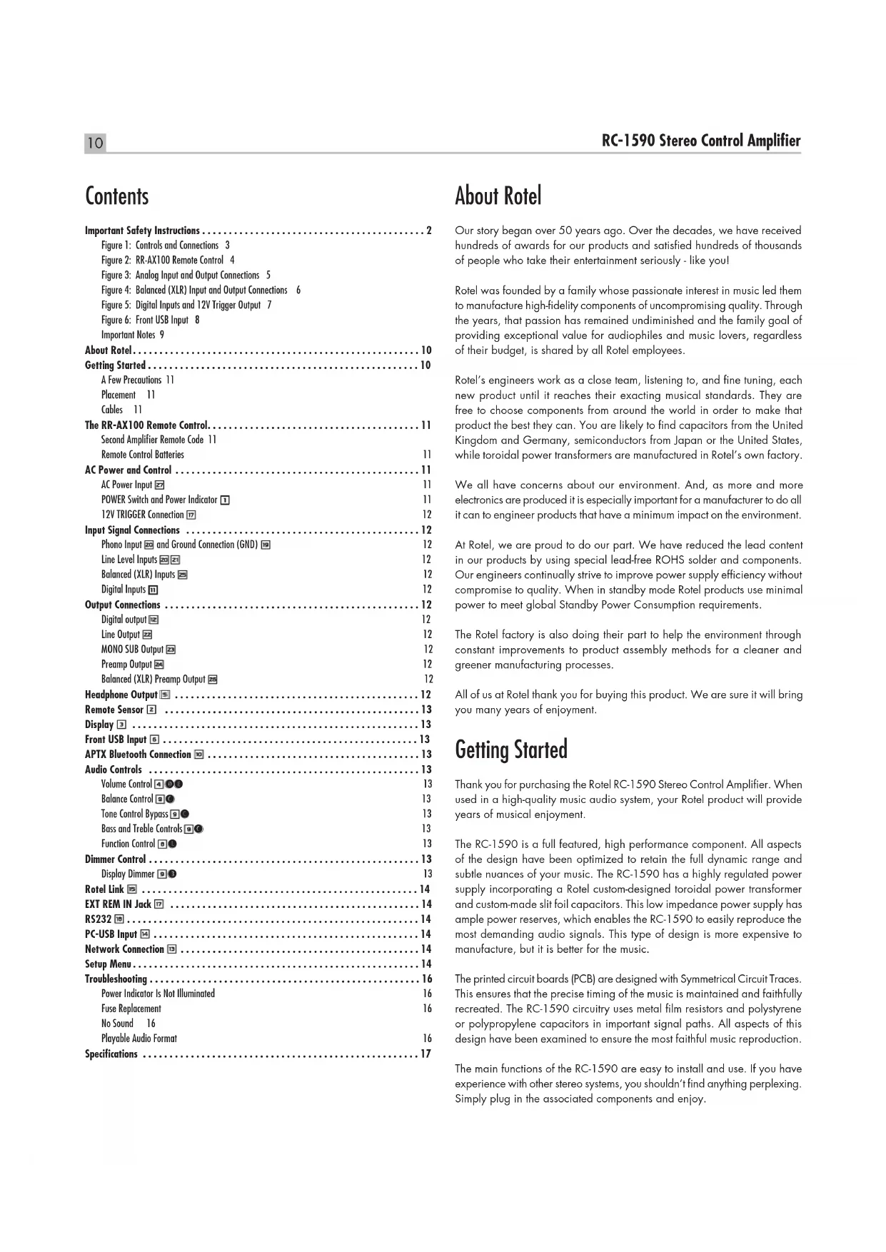
Important Safety Instructions 2
Figure 1: Controls and Connections 3
Figure 2: RR-AX100 Remote Control 4
Figure 3: Analog Input and Output Connections 5
Figure 4: Balanced (XLR) Input and Output Connections 6
Figure 5: Digital Inputs and 12V Trigger Output 7
Figure 6: Front USB Input 8
Important Notes 9
About Rotel....10
Getting Started....10
A Few Precautions 11
Placement 11
Cables 11
The RR-AX100 Remote Control....11
Second Amplifier Remote Code 11
Remote Control Batteries 11
AC Power and Control 11
AC Power Input 27 11
POWER Switch and Power Indicator 11
12V TRIGGER Connection 17 12
Input Signal Connections 12
Phono Input 20 and Ground Connection (GND) 19 12
Line Level Inputs 20 21 12
Balanced (XLR) Inputs 12
Digital Inputs 12
Output Connections 12
Digital output 12 12
Line Output 22 12
MONO SUB Output 23 12
Preamp Output 24 12
Balanced (XLR) Preamp Output 25 12
Headphone Output 12
Remote Sensor 2 13
Display 3 13
Front USB Input 13
APTX Bluetooth Connection 10 13
Audio Controls 13
Volume Control 4 13 13
Balance Control 13
Tone Control Bypass 13
Bass and Treble Controls 13
Function Control 13
Dimmer Control 13
Display Dimmer 13
Rotel Link 14
EXT REM IN Jack 17 14
RS232 18 14
PC-USB Input 14 14
Network Connection 13 14
Setup Menu....14
Troubleshooting 16
Power Indicator Is Not Illuminated 16
Fuse Replacement 16
No Sound 16
playable Audio Format 16
Specifications 17
About Rotel
Our story began over 50 years ago. Over the decades, we have received hundreds of awards for our products and satisfied hundreds of thousands of people who take their entertainment seriously - like you!
Rotel was founded by a family whose passionate interest in music led them to manufacture high-fidelity components of uncompromising quality. Through the years, that passion has remained undiminished and the family goal of providing exceptional value for audiophiles and music lovers, regardless of their budget, is shared by all Rotel employees.
Rotel's engineers work as a close team, listening to, and fine tuning, each new product until it reaches their exacting musical standards. They are free to choose components from around the world in order to make that product the best they can. You are likely to find capacitors from the United Kingdom and Germany, semiconductors from Japan or the United States, while toroidal power transformers are manufactured in Rotel's own factory.
We all have concerns about our environment. And, as more and more electronics are produced it is especially important for a manufacturer to do all it can to engineer products that have a minimum impact on the environment.
At Rotel, we are proud to do our part. We have reduced the lead content in our products by using special lead-free ROHS solder and components. Our engineers continually strive to improve power supply efficiency without compromise to quality. When in standby mode Rotel products use minimal power to meet global Standby Power Consumption requirements.
The Rotel factory is also doing their part to help the environment through constant improvements to product assembly methods for a cleaner and greener manufacturing processes.
All of us at Rotel thank you for buying this product. We are sure it will bring you many years of enjoyment.
Getting Started
Thank you for purchasing the Rotel RC-1590 Stereo Control Amplifier. When used in a high-quality music audio system, your Rotel product will provide years of musical enjoyment.
The RC-1590 is a full featured, high performance component. All aspects of the design have been optimized to retain the full dynamic range and subtle nuances of your music. The RC-1590 has a highly regulated power supply incorporating a Rotel custom-designed toroidal power transformer and custom-made slit foil capacitors. This low impedance power supply has ample power reserves, which enables the RC-1590 to easily reproduce the most demanding audio signals. This type of design is more expensive to manufacture, but it is better for the music.
The printed circuit boards (PCB) are designed with Symmetrical Circuit Traces. This ensures that the precise timing of the music is maintained and faithfully recreated. The RC-1590 circuitry uses metal film resistors and polystyrene or polypropylene capacitors in important signal paths. All aspects of this design have been examined to ensure the most faithful music reproduction.
The main functions of the RC-1590 are easy to install and use. If you have experience with other stereo systems, you shouldn't find anything perplexing. Simply plug in the associated components and enjoy.
A Few Precautions
WARNING: To avoid potential damage to your system, turn off ALL the components in the system when connecting or disconnecting the loudspeakers or any associated components. Do not turn the system components back on until you are sure all the connections are correct and secure. Pay particular attention to the speaker wires. There must be no loose strands that could contact the other speaker wires, or the chassis of the amplifier.
Please read this manual carefully. In addition to basic installation and operating instructions, it provides valuable information on various RC-1590 system configurations as well as general information that will help you get optimum performance from your system. Please contact your authorized Rotel dealer for answers to any questions you might have. In addition, all of us at Rotel welcome your questions and comments.
Save the RC-1590 shipping carton and all enclosed packing material for future use. Shipping or moving the RC-1590 in anything other than the original packing material may result in severe damage to your amplifier.
If included in the box please fill out and send in the owner's registration card. Also be sure to keep the original sales receipt. It is your best record of the date of purchase, which you will need in the event warranty service is ever required.
Placement
Like all audio components that handle low-level signals, the RC-1590 can be affected by its environment. Avoid placing the RC-1590 on top of other components. Also avoid routing audio signal cables near power cords. This will minimize the chance it will pick up hum or interference.
The RC-1590 is supplied with an RR-AX100 remote control and must be placed where the infrared signal from the remote can reach the front panel Remote Sensor.
Cables
Be sure to keep the power cords, digital signal cables and regular audio signal cables in your installation away from each other. This will minimize the chance of the regular audio signal cables picking up noise or interference from the power cords or digital cables. Using only high quality, shielded cables will also help to prevent noise or interference from degrading the sound quality of your system. If you have any questions see your authorized Rotel dealer for advice about the best cable to use with your system.
The RR-AX100 Remote Control
Some functions can be done with either the front panel controls, or the supplied RR-AX100 remote control. When these operations are described, the square call out numbers refer to the main unit, while the encircled letters refer to the remote control.
Second Amplifier Remote Code
The factory setting is remote code 1. If you find that the remote is conflicting with other Rotel amplifiers, you can change to remote code 2 with the following steps.
-
From the remote control press Tuner L and 2 M at the same time to set the remote control to send Audio Code 2.
-
Point the remote at the unit and press 2 Ⓜ key for 8 seconds. The unit will show "Audio Custom Code 1 -> 2".
- Repeat the above procedure and press "1" key instead of "2" to change the unit back to Code 1.
NOTE: The remote control can be used to operate the basic functions of Rotel tuners and CD players. Remote control buttons labeled I K M N can be used to operate CD or Tuner functions in your system. For the remote control to operate properly, make sure both the remote control and the CD or Tuner are both in same remote code. For more information please contact your authorized Rotel dealer.
Remote Control Batteries
Two AA size batteries (supplied) must be installed before the remote control can be used. To install the batteries, remove the cover on the back of the RR-AX100. Install the batteries as shown in the illustration in the battery well. Test the control for proper operation, then replace the cover. When the batteries become weak the remote control won't operate the RC-1590 consistently. Installing fresh batteries should eliminate the problem.
AC Power and Control
AC Power Input 27
Your RC-1590 is configured at the factory for the proper AC line voltage in the country where you purchased it (either 120 volts AC or 230 volts AC with a line frequency of either 50 Hz or 60 Hz). The AC line configuration is noted on a decal on the back panel.
NOTE: Should you move your unit to another country, it may be possible to reconfigure it for use on a different line voltage. Do not attempt to perform this conversion yourself. Opening the enclosure of the unit exposes you to dangerous voltages. Consult a qualified service person or the Rotel factory service department for information.
NOTE: Some products are intended for sale in more than one country and as such are supplied with more than one AC cord. Please only use the one appropriate for your country/region.
The RC-1590 should be plugged directly into a 2-pin polarized wall outlet. Do not use an extension cord. A heavy duty multi-tap power outlet strip may be used if it (and the wall outlet) is rated to handle the current demanded by the RC-1590 and all the other components connected to it.
If you are going to be away from home for an extended period of time such as a month long vacation, it is a sensible precaution to unplug the RC-1590 (as well as other audio and video components) while you are away.
POWER Switch and Power Indicator ☐
Press the front panel Power Switch button to turn the unit on. The Power Indicator light is illuminated when the unit is on. Press the Power Switch button again to turn the unit off.
When the power switch is in the ON position, the remote control ON and OFF buttons may be used to activate the RC-1590. In Standby mode the power LED remains illuminated, but the display is turned OFF.
NOTE: Place the self adhesive ring over the light surrounding the power switch if the blue light is too bright.
12V TRIGGER Connection 17
Some audio components can be turned on automatically when they receive a 12V turn on "signal". The two 12V Trigger Outputs on the RC-1590 provide the required signal. Connect compatible components to the RC-1590 with a conventional 3.5mm mini mono plug cable. When the RC-1590 is in standby mode, the trigger signal is disabled, so the components controlled by it will be turned off.
NOTE: Do not connect both the Rotel Link and 12V trigger cables at the same time. The 12V trigger's power on or off features will override the Rotel Link features.
Input Signal Connections
See Figure 3
NOTE: To prevent loud noises that neither you nor your speakers will appreciate, make sure the system is turned off when you make any signal connections.
Phono Input 20 and Ground Connection (GND) 19
See Figure 3
Plug the cable from the turntable into the appropriate left and right phono inputs. If the turntable has a "ground" wire, connect it to the screw terminal to the left of the Phono inputs. This will help prevent hum and noise.
Line Level Inputs 20 21
See Figure 3
The CD, Tuner, and Aux inputs of the amplifier are analog "line level" inputs. These inputs are for connecting components such as CD players or other audio playback devices with an analog audio output.
The left and right channels are clearly labeled and should be connected to the corresponding channels of the source component. The Left connectors are white, the Right connectors are red. Use high quality RCA cables for connecting input source components to the RC-1590. Ask your authorized Rotel dealer for advice about cables.
Balanced (XLR) Inputs 25
See Figure 4
A pair of balanced XLR inputs accept audio signals from CD player, Blu-ray player or other source components with XLR outputs.
NOTE: You should choose only one method of analog connection from a source component to RC-1590. Do not connect both the RCA and XLR outputs of a source component to the RC-1590 at the same time.
Digital Inputs 11
See Figure 5
There are three sets of digital inputs labeled 1, 2 and 3, for COAXIAL and OPTICAL respectively. Connect the COAXIAL or OPTICAL PCM outputs of your source component into these sockets. The digital signals will be decoded and played by the RC-1590. The unit is capable of decoding PCM signals up to 24 bit, 192kHz.
Output Connections
Digital output 12
If you are using an outboard D/A converter or other digital processor, you will need an unprocessed digital data stream from the RC-1590. Using a standard 75 ohm coax/optical digital cable, connect the RC-1590's digital output to the digital input connector on the outboard D/A converter.
Line Output zz
The line output connectors can be used to send the analog audio to a separate processor device. These outputs bypass the volume encoder and are full line level output. They should be connected to the analog inputs of the processor. As with other sources be sure to connect the Left and Right channels of each device to the proper channels on the associated components. Use high quality connecting cables to prevent loss of sound quality.
MONO SUB Output 23
There are 2 connectors for mono subwoofer output to connect to a subwoofer. These mono outputs are summed with both the left and right audio signal. They are parallel outputs allowing 2 subwoofers to be connected to the RC-1590.
Preamp Output 24
See Figure 3
The RC-1590 RCA-type output connectors are compatible with most power amplifiers. As always, select high quality audio interconnect cables. Connect the left and right channel outputs of the RC-1590 to the corresponding inputs on the amplifier or other component.
NOTE: There are two sets of RCA outputs on the RC-1590. The second set of outputs may be used in custom system configurations to drive a second power amplifier or to supply a signal to a special signal processor.
Balanced (XLR) Preamp Output 26
See Figure 4
Two pairs of XLR balanced connectors supply an analog output signal from the RC-1590 to a power amplifier with XLR balanced input connectors.
NOTE: Do not connect both the RCA and XLR to the same amplifier at the same time.
Headphone Output 5
The headphone output allows you to connect headphones for private listening. This output accepts a standard 3.5mm (1/8") mini stereo headphone connector. Plugging in a set of headphones does not cut off the signal to the preamp outputs. In most instances you should turn off the power amplifier when listening to headphones.
NOTE: Because the sensitivity of speakers and headphones can vary widely, always reduce the volume level before connecting or disconnecting headphones.
Remote Sensor z
This remote sensor window receives IR commands from the remote control. Please do not block this sensor.
Display 3
The front panel display shows the source selected, volume level and tone settings. The display can be dimmed using the RC-1590 setup menu or the IR remote controller. See the Dimmer Control section of this manual for details.
Front USB Input 6
See Figure 6
The front USB input can be connected to an iPod or iPhone. With iPod or iPhones, simply plug the device into the front USB and select USB function from the source selector. The iPod and iPhone remain active allowing search and play functions.
APTX Bluetooth Connection 10
The Bluetooth Antenna 10 on the RC-1590's back panel is for wireless streaming via Bluetooth, from your device (i.e. mobile phones). From your mobile device, look for "Rotel Bluetooth" and connect to it. Connection is normally automatic, but if prompted for a password, please press "0000" on your device. The RC-1590's supports both traditional Bluetooth and APTX Bluetooth audio streaming.
Audio Controls
Volume Control 4 D E
Turn the knob clockwise to increase the volume, or counter clockwise to decrease the volume. From the remote control press the volume + or - D button to turn the volume up or down. Press the MUTE E button to completely mute the volume.
Balance Control 9 C
The Balance Control adjusts the left-to-right balance of the sound output. The factory default is the center position or "0". To change the balance from the front panel, press the MENU button to toggle the front display to BALANCE SETTING mode. Then press the - or + buttons on the front panel to change the value to LEFT or RIGHT. The value can change from L15 to R15.
NOTE: This setting is saved permanently including after powering off the RC-1590.
To make temporary changes not saved after power off, from the remote control press the BAL C button to access the BALANCE setting, then press the left/right G arrow buttons to adjust. When finished, press the ENTER G button to exit the menu.
Tone Control Bypass 9 C
Bass and Treble Control (Tone Control) circuits are bypassed at factory default to ensure the purest possible sound. The front display will show TONE BYPASS. To turn on the tone control from the front panel, press the MENU button to toggle to the Bypass control then press the - or + buttons on the front panel to turn bypass on or off.
NOTE: This setting is saved permanently including after powering off the RC-1590.
To temporarily change the Tone Control Bypass, press the TONE button on the front panel, then press the - or + button on the front panel to turn the Bypass on or off, or press the BYPASS button on the remote control.
Bass and Treble Controls 9 C
Set the Bass or Treble controls from the front panel by pressing the MENU button to toggle to either the Bass or Treble Setting menu. Then press the - or + button on the front panel to adjust the value. The Bass and Treble values range from -10 to +10.
NOTE: These settings are saved permanently including after powering off the RC-1590.
To temporarily change the Bass and Treble settings, press the TONE button on the front panel to toggle to the Bass or Treble Setting, then press the - or + button on the front panel to adjust the value. Or from the remote control, press the BASS or TREBLE button, then press the left/right arrow buttons on the remote control.
NOTE: When Tone Bybass is disabled, Bass and Treble settings can not be changed by the Tone button 7 or the BASS/TREBLE buttons C.
A properly setup high-performance audio system produces the most natural sound with little or no adjustment of the tone controls. Use these controls sparingly. Be particularly careful when turning the controls up as this increases the power output in the bass or treble range, increasing the load on the amplifier and speakers.
NOTE: Setting the Bass and Treble controls do not automatically turn on the tone control. To turn on tone control, refer to previous section Tone Control Bypass.
NOTE: Tone Bypass, Bass, Treble and Balance settings are only saved permanently from within the Menu. Adjustments made using the 7 button are temporary only and not saved after power off.
Function Control ☐ L
The Function control selects the input signal source. From the front panel or remote control press the corresponding input button to select the source to listen to.
Dimmer Control
Display Dimmer 9 B
To change the brightness of the front display, press the MENU button to toggle to the Display Settings. Then press the - or + buttons on the front panel to change the display brightness.
NOTE: This setting is saved permanently including after powering off the RC-1590.
To temporarily change the display brightness, press the DIM B button on the remote control.
NOTE: Display Dimmer setting is only saved permanently from within the Menu. Adjustment made using the Ⓑ button is temporary only and not saved after power off.
Rotel Link 15
The ROTEL LINK OUT connection can be made with the stereo 3.5 mm cable (supplied) to a Rotel integrated amplifier and CD player. While the ROTEL LINK IN can optionally attach to Rotel network enabled products with ROTEL LINK OUT connections.
These allow the attached Rotel products to communicate with each other and be controlled via the Rotel Remote App (available for download on the iTunes ^® store).
NOTE: Only the Rotel Link cables supplied with this product should be used. These 3.5 mm cables have WHITE connector ends and should not be confused with the 12 Volt Trigger cables that have BLACK connector ends.
EXT REM IN Jack 17
This 3.5mm mini-jack receives command codes from industry-standard infrared receivers via hard-wired connections. This feature could prove useful when the unit is installed in a cabinet and the front-panel sensor is blocked. Consult your authorized Rotel dealer for information on these external repeaters and the proper wiring of a jack to fit the mini-jack receptacle.
RS232 18
The RC-1590 can be controlled via RS232 for integration with automation systems. The RS232 input accepts a standard straight DB-9 Male-to-Female cable.
For additional information on the connections, software, and operating codes for computer control of the RC-1590, contact your authorized Rotel dealer.
PC-USB Input 14
See Figure 5
Connect this input using the supplied USB cable to the PC-USB socket of your computer.
The RC-1590 supports both USB Audio Class 1.0 and USB Audio Class 2.0 modes. Windows computers do not require installation of a driver for USB Audio Class 1.0 and support playback of audio up to 96kHz sampling rates. The Factory Default setting is USB Audio Class 1.0.
To take advantage of USB Audio Class 2.0 audio playback supporting up to 384kHz sampling rates you will need to install the Windows driver supplied on CD included with the RC-1590. You will also need to switch the RC-1590 to USB Audio Class 2.0 playback mode with the following:
- Press MENU on the front panel until "PC-USB AUDIO CLASS" appears on the display.
- Select "2.0" using the "-" button then press "ENTER".
- Power cycle the RC-1590 and reboot your PC after changing the USB Audio mode to ensure both units are properly configured.
Many audio playback applications do not support 384kHz sampling rate. Please confirm your audio player supports 384kHz audio and you have 384kHz audio files to properly playback this sample rate. Also, you may need to configure the audio driver in your PC to output 384kHz or your computer may "down sample" to a lower audio sample rate. For more information please refer to your audio player or operating system information.
NOTE: USB Audio Class 2.0 requires installation of the Windows PC driver on the CD ROM included with the RC-1590.
NOTE: MAC computers do not require a driver to support PC-USB 1.0 or 2.0 audio.
NOTE: Upon successful installation of the driver, you may need to select the ROTEL audio driver from the audio/speaker setup of your computer.
NOTE: The RC-1590 supports both DSD and DOP audio playback in 1X and 2X formats. Consult your audio player to confirm proper operation for playback of these audio formats.
Network Connection 13
The RC-1590 can be attached to a network using the rear panel NETWORK socket. The NETWORK configurations allow both static and DHCP IP addressing. See the Network Setup section of this manual under Setup Menu for IP address configuration information.
The NETWORK connections allows software updates to be downloaded from the Internet. The Network connection also allows IP control for integration with automation systems.
For additional information on the IP connection please contact your authorized Rotel dealer.
Setup Menu
You can access the settings menu from the front panel by pressing the MENU button or the SETUP button on the remote control. You can change the value of the selected option by pressing the +/- button on the front panel or the left/right arrow buttons on the remote control. Step through the sub-menus by pressing the MENU button on the front panel or SETUP button on the remote control.
- TONE Control: TONE BYPASS ON/OFF, BASS level and TREBLE levels can be changed to desired settings. Press the ENTER button on the front panel or on the remote control to toggle between the tone setup options. (For more information on Tone Control refer to the Tone Control Bypass, Bass and Treble control sections.)
NOTE: These settings are stored permanently even after the RC-1590 is powered off.
- BALANCE: Changes left/right balance. (For more information on Balance sections.)
NOTE: This setting is stored permanently even after the RC-1590 is powered off.
- DIMMER: Dims the display.
NOTE: This setting is stored permanently even after the RC-1590 is powered off.
- ROTEL LINK RCD: Selects how the CD player is connected to the amplifier, either CD (analog), COAX1, COAX2 and BAL-XLR. CD is the factory default.
- POWER ON MAX VOLUME: This sets the maximum volume level when the unit is turned ON. "45" is the factory default.
NOTE: Power On Max Volume settings do not apply to sources configured with Fixed Gain.
- POWER OPTION: Enables the RC-1590 to be controlled via the network port when attached to an automation system. The power consumption is higher in Quick Power mode. If network control is not required select the Normal Power mode. "Normal" is the factory default.
Valid settings include: Normal, Quick.
NOTE: When the POWER OPTION is configured to Quick, the RC-1590 will consume additional power in standby mode.
NOTE: Some regions limit the amount of Standby Power Consumption allowed and the POWER OPTION function will not be available. To control the Rotel product in this case use the RS232 connection. For questions on the availability of the Power Option please contact your authorized Rotel dealer.
- AUTO POWER OFF: The RC-1590 can be configured to automatically power off if unused for a specified period. If no changes are made to the unit within the specified "Auto Power Off" timer the unit will automatically go to STANDBY mode. The Auto Power Off timer will be restarted if changes are made to the volume, source or playback. The default for Auto Power Off is set to DISABLE.
Valid settings include: DISABLE, 1 HOUR, 2 HOURS, 5 HOURS, 12 HOURS.
NOTE: Some regions require the AUTOMATIC POWER OFF timer default setting to be 20 minutes. This can be changed in the SETUP MENU to any of the available options. For questions about the Automatic Power Off settings please contact your authorized Rotel dealer.
NOTE: Some products cannot detect ANALOG signal inputs and the unit may power off if there is no digital audio source detected or user action with the remote control or front panel. Analog input signal detection is not available in all models which may cause the unit to inadvertently power off. In this case the Automatic Power Off timer should be set to DISABLED.
- FIXED GAIN: Configures a Fixed Volume level for a specified input. To enable this feature press the +/- buttons on the front panel to select the desired fixed volume level for Aux, FUSB, PC-USB, Coax 1, Coax 2, Optical 1, Optical 2 or Bluetooth. When enabled and the input with a
Fixed Volume is selected, the Volume level will immediately be set to the specified level.
Valid settings include: VARIABLE, FIXED 01-95, FIXED MAX.
- AUX VOL: VARIABLE (disabled) is factory default.
- FUSB VOL: VARIABLE (disabled) is factory default.
• PC-USB VOL: VARIABLE (disabled) is factory default. - OPT1 VOL: VARIABLE (disabled) is factory default.
- OPT2 VOL: VARIABLE (disabled) is factory default.
• COAX1 VOL: VARIABLE (disabled) is factory default.
• COAX2 VOL: VARIABLE (disabled) is factory default. - BLUETOOTH VOL: VARIABLE (disabled) is factory default.
NOTE: The Volume knob on the front panel and Volume +/- buttons on the IR remote are disabled when the volume is Fixed. To disable this feature set the Fixed Volume level to "Variable".
- PC-USB AUDIO CLASS: Changes supported PC-USB Audio Class of the attached device.
NOTE: Some computers attached to the PC-USB do not support USB Audio Class 2.0 and do not support 32/384 audio playback. If needed the PC-USB can be configured for USB Audio Class 1.0. Please consult your computer operating system for details.
- NETWORK: Shows the network connection status and to view/configure the network settings. If the network is properly configured and attached "Connected" will be displayed. To view or modify the network settings press the ENTER button.
The RC-1590 supports both DHCP and STATIC IP addressing. Select the desired IP address method and press ENTER.
If DHCP is selected you can refresh IP address by pressing ENTER or press MENU to view IP address information. Press the MENU button to toggle through IP address settings. If the IP address is renewed the network will be tested and connection status reported.
If STATIC IP address mode is selected you must configure all settings for the network including IP Address, Subnet Mask, Gateway and DNS Server. Use the left/right or +/- buttons to adjust the values and press ENTER to move to the next value. When the proper IP information is configured press MENU to go to the next setting. After entering the STATIC IP address information the network will be tested and connection status reported.
NOTE: For more information regarding network connection please contact your authorized Rotel dealer.
NOTE: A network connection is not required for the RC-1590 to operate.
- MAIN: This shows the current software version loaded into the RC-1590. The software can be updated if the RC-1590 is properly connected to the Internet.
- Press ENTER to check if a new software version is available.
- If a new software version is available press the + button on the front panel or the right button on the remote control to select YES then press ENTER button to begin the software update process.
- The new software will be downloaded from the Internet. The RC-1590 will power cycle when the software update is complete.
NOTE: Do NOT power off the RC-1590 during the software update process.
NOTE: It is recommended to Reset Factory Defaults after the software update is complete.
- PC-USB: This shows current loaded software version for PC-USB processor.
- FACTORY DEFAULT: This sets the unit back to the original state as when it left the factory. Press the + button on the front panel or the Right button on the remote control to select
NOTE: All previously configured options will be erased and reset to the factory default settings.
Troubleshooting
Most difficulties in audio systems are the result of incorrect connections, or improper control settings. If you encounter problems, isolate the area of the difficulty, check the control settings, determine the cause of the fault and make the necessary changes. If you are unable to get sound from the RC-1590, refer to the suggestions for the following conditions:
Power Indicator Is Not Illuminated
The Power Indicator ring around the power button and the basic items in the Display window should be illuminated whenever the RC-1590 is plugged into the wall power outlet and the POWER switch is pushed in. If it does not light, test the power outlet with another electrical device, such as a lamp. Be sure the power outlet being used is not controlled by a switch that has been turned off.
Fuse Replacement
If another electrical device works when plugged into the power outlet, but the Power Indicator still will not light when the RC-1590 is plugged into the wall outlet, it indicates that the internal power fuse may have blown. If you believe this has happened, contact your authorized Rotel dealer to get the fuse replaced.
No Sound
Check the signal source to see if it is functioning properly. Make sure the cables from the signal source to the RC-1590 inputs are connected properly. Check all the wiring between the RC-1590 and the power amplifier, and the speakers.
playable Audio Format
USB Apple (iPhone, iPod, iPad)
| Format Notes | |
| Any supported file loaded to Apple device. | Any supported file loaded to Apple device. Phone may resample depending on stored format. May exclude Apps designed to play formats not originally supported by the sending device. |
APTX Bluetooth
| Format Notes | |
| Any format supported by the sending device. | May exclude Apps designed to play formats not originally supported by the sending device. |
PC-USB
| Format Notes | |
| Format determined by the Media Player/Server software that you use. | Any supported format by the PC softwarePCM Audio: 44.1k, 48k, 88.2k, 96k, 176.4k, 192k, 384k (16 bit, 24 bit and 32 bit)DSD64 and DSD128 |
Coax/Optical
| Format Notes | |
| SPDIF LPCM | 44.1k, 48k, 88.2k, 96k, 176.4k, 192k16 bit, 24 bit |
Specifications
Total Harmonic Distortion (20 Hz - 20kHz) < 0.002%
Input Sensitivity / Impedance
Phono Input (MM) 2.5 mV / 47k ohms Line Level Inputs (RCA) 150 mV / 100k ohms Line Level Inputs (XLR) 250 mV / 100k ohms
Output Level
Line Level (RCA) 1 V Balanced (XLR) 2 V
Frequency Response:
Phono Input 20 Hz · 20k Hz, 0 ± 0.2 dB Line Level Inputs 10 Hz · 100k Hz, 0 ± 0.1 dB
Signal to Noise Ratio (A weighting)
Phono Input 80 dB Line Level Inputs 112 dB
Channel Separation
Phono Input >75 dB Line Level Inputs >75 dB
Digital Section
Frequency Response 20Hz - 20kHz (±0.5 dB, Max)
Signal to Noise Ratio (A weighting) 108 dB
Digital Inputs SPDIF LPCM
| PCUSB | (up to 192kHz 24 bit)USB Audio Class 1.0(up to 96kHz 24 bit)USB Audio Class 2.0(up to 384kHz 32bit)**Driver installation required |
General
Power Requirements:
| USA: | 120 Volts, 60 Hz |
| EC: | 230 Volts, 50 Hz |
| Power Consumption 45 watts | |
| Standby Power Consumption | < 0.5 watts |
| BTU | 78 BTU/h |
| Dimensions (W x H x D) | 431 x 144 x 348 mm(17 x 5 ^11/_16 x 13 ^7/_9 ins) |
| Front Panel Height | 3U (132.6 mm, 5 ^1/_4 ins) |
| Weight (net) | 9.2 kg, 20.28 lbs. |
All specifications are accurate at the time of printing.
Rotel reserves the right to make improvements without notice.
Rotel and the Rotel Hi-Fi logo are registered trademarks of The Rotel Co., Ltd, Tokyo, Japan.
"Made for iPod," and "Made for iPhone," means that an electronic accessory has been designed to connect specifically to iPod or iPhone, respectively, and has been certified by the developer to meet Apple performance standards. Apple is not responsible for the operation of this device or its compliance with safety and regulatory standards. Please note that the use of this accessory with iPod, or iPhone may affect wireless performance.
iPhone, iPod, iPod classic, iPod nano, and iPod touch are trademarks of Apple Inc., registered in the U.S. and other countries.
Made for

iPod

iPhone
Ajustements Graves/Aigus
PC-USB USB Audio Class 1.0
Dimensions (L, H, P)
431×144×348 mm
(17" × 5
^11/16'' × 13^7/9''
Ausgangsanschlüsse....31
Control VOLUME 4 D E
PC-USB USB Audio Class 1.0
(hasta 24 bits/96 kHz) USB Audio Class 2.0 (hasta 32 bits/384 kHz)*
Line Level (RCA) 1 V
Balanced (XLR) 2 V
Frequentiebereik:
Phono-ingang 20 Hz - 20 kHz, 0 ± 0.2 dB
Lijningangen 10 Hz - 100 kHz, 0 ± 0,1 dB
PC-USB USB Audio Class 1.0
(tot 192kHz, 24 bits)
(tot 96kHz, 24 bits)
USB Audio Class 2.0
(tot 384 kHz 32 bits)*
Controlli audio....60
Volume 4 16 60
Bilanciamento 60
PC-USB USB Audio Class 1.0
(fino a 96 kHz, 24 bit)
USB Audio Class 2.0
(fino a 384 kHz, 32bit)*
PC-USB USB Audio Class 1.0
(upp till 24/96)
USB Audio Class 2.0
(upp till 32/384)*
* Kräver installerad drivrutin
Allmänt:
Strömförsörjning
| Europa | 230 volt, 50 Hz |
| USA | 120 volt, 60 Hz |
Strömförbrukning
2-11-4, Nakane, Meguro-ku,
Tokyo, 152-0031
Japan
Rotel of America
54 Concord Street
North Reading, MA 01864-2699
USA
Phone: +1 978-664-3820
Fax: +1 978-664-4109
Rotel Europe
Dale Road
Worthing, West Sussex BN11 2BH
England
Phone: +44 (0)1903 221 763
Fax: +44 (0)1903 221 525
Rotel Deutschland
- Important Safety Instructions
- Notice
- Important Notes
- When making connections be sure to:
- It is also recommended that you:
- Remarques importantes
- About Rotel
- Getting Started
- A Few Precautions
- Placement
- Cables
- The RR-AX100 Remote Control
- Second Amplifier Remote Code
- Remote Control Batteries
- AC Power and Control
- AC Power Input 27
- POWER Switch and Power Indicator ☐
- 12V TRIGGER Connection 17
- Input Signal Connections
- Phono Input 20 and Ground Connection (GND) 19
- Line Level Inputs 20 21
- Balanced (XLR) Inputs 25
- Digital Inputs 11
- Output Connections
- Digital output 12
- Line Output zz
- MONO SUB Output 23
- Preamp Output 24
- Balanced (XLR) Preamp Output 26
- Headphone Output 5
- Remote Sensor z
- Display 3
- Front USB Input 6
- APTX Bluetooth Connection 10
- Audio Controls
- Volume Control 4 D E
- Balance Control 9 C
- Tone Control Bypass 9 C
- Bass and Treble Controls 9 C
- Function Control ☐ L
- Dimmer Control
- Display Dimmer 9 B
- Rotel Link 15
- EXT REM IN Jack 17
- RS232 18
- PC-USB Input 14
- Network Connection 13
- Setup Menu
- Troubleshooting
- Power Indicator Is Not Illuminated
- Fuse Replacement
- No Sound
- playable Audio Format
- Specifications
- Input Sensitivity / Impedance
- Output Level
- Frequency Response:
- Signal to Noise Ratio (A weighting)
- Channel Separation
- Digital Section
- General
- Made for
- Ajustements Graves/Aigus
- Control VOLUME 4 D E
- Frequentiebereik:
- Allmänt:
- Strömförsörjning
- Strömförbrukning
- Rotel of America
- Rotel Europe
- Rotel Deutschland
Brand : ROTEL
Model : RC1590
Category : Receiver