BWS 02 - Washing machine MIELE - Free user manual and instructions
Find the device manual for free BWS 02 MIELE in PDF.
User questions about BWS 02 MIELE
0 question about this device. Answer the ones you know or ask your own.
Ask a new question about this device
Download the instructions for your Washing machine in PDF format for free! Find your manual BWS 02 - MIELE and take your electronic device back in hand. On this page are published all the documents necessary for the use of your device. BWS 02 by MIELE.
USER MANUAL BWS 02 MIELE
PW6163,PW6243,PW6323
| de | MontageanweisungBWS02Schaumkompensator(Bausatz Wrasen-undSchaumableitung)Reine-Unreine-Seite | en | Fittinginstructions-BWS02foomcompensator(vapourandfoamissipationkit),clean/soiledside | fr | NoticedemontagedérivateurdemousseBWS02(jeud'adaptationdérivationbuéesetmousse)côtépropre-côtécontaminé |
| ni | Montage-instructieBWS02Schuimcompensator(onderdeelwasm-enschuimafvoer)schone-vuile-zijde | da | MonteringsanvisingBWS02skumkompensator(ombygnings-sætem-ogskumafledning)ren-uren-side | sv | MonteringsanvisingBWS02skumkompensator(byggsatsforäng-ochskumavledning)renresp.orensida |
| it | IstruzionidimontaggioBWS02compensatoreschiuma(setdi montaggioscaricofumanee schiuma)latoasettico-infetto | es | InstruccionesdemontajedelscompensadordeespumabWS02(Juegodemontajedelaconducciónvahosyespuma)ladocomtaminado/ descontaminado. | el | ÖbnyiaTOnoθετηηçBWS02ποεναιμετρουαφρου(σεTtoTOnoθετηηçγιατηναποχετευημηūρατμωκαίαφρου)καθαρή-ακαθαρτη-πλερά |
| am | InstallationInstructions-BWS02FoamCompensator(VaporandFoamDissipationKit),Clean/SoiledSide |
2
3
4
5
6
7
9
8
10
This service and repair work should only be carried out by a suitably qualified electrician (with specialist training, knowledge and experience, and recent related work experience) in accordance with all appropriate local and national safety regulations.
Servicing, modification, testing and maintenance of electrical appliances should only be carried out in accordance with all appropriate legal requirements, accident prevention regulations and valid standards. All regulations of the appropriate utility supply companies and standardsrelatingtosafety(notlimitedtoelectricalsafety)aretobecompliedwith.
Danger!
Evenwiththemachineswitchedoff,mainsvoltagemaybeappliedtosomecomponents.
Before any service work is commenced, the machine must be disconnected from the mains. Suitable measurements must be made to ensure that this is the case.
Ageneralsualcheckshouldalwaysbocarriedout.
Incorrectconversionorserviceworkcouldleadtoariskoffire.
Note
Thekit,Mat.no.07555850,forPW6163,PW6243andPW6323,containsthefollowing:
-1branchpipe75x50,45°
-1pipebend50x45°
4hoseclipsSGL50-70
-1hosel
-1hosell
-1connectionpiece
· 1 pipebendDN50x45°(pipebendhosefastening)
-1 ring(reinforcingringforpipebendhosefastening)
-1connectionpiece1
-1connectionpiece2
-1 holdingplate
-2raised-headscrewsCEM6x16
-1adapterforvapour/foamdissipation
2raised-headscrews4x15
-1foamadhesivetape0.5m
-1pipe110x500
-1pipe110x50
1sleeve110
-3bends50x87
-1pipe50x100
Fitting instructions - BWS 02 foam compensator (vapour and foam dissipation kit), Mat. no. 07553950.
Listofillustrations:
Fig.1:Sidecasingremoval
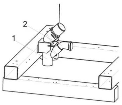
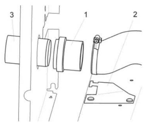
Fig.2: Branchpiecefitting, viewfromright
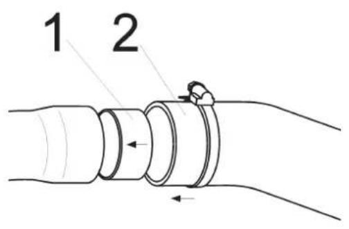
Fig.3:Hoselandhosellpreassembly
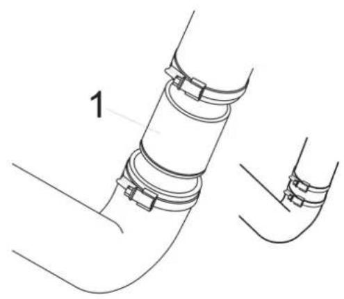
Fig.4:Pipebendhosefixingpreassembly
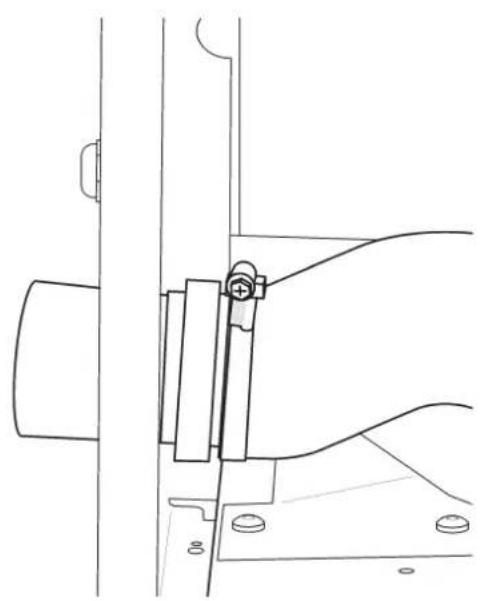
Fig.5:Drainconnection/viewfromright
-Fig.6:Sidecasingthrough-feedfitting
Fig.7:Sidecasingfitting
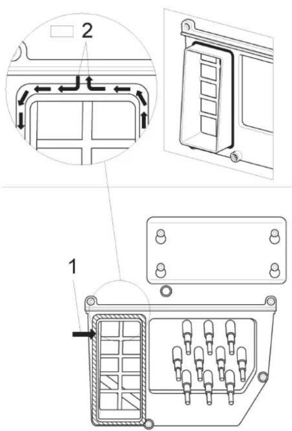
-Fig.8:Fittingfoamadhesivetape
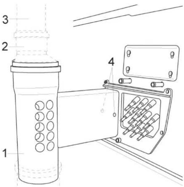
-Fig.9:Fitting,drillingandfasteningthevapourandfoamdissipationadapter
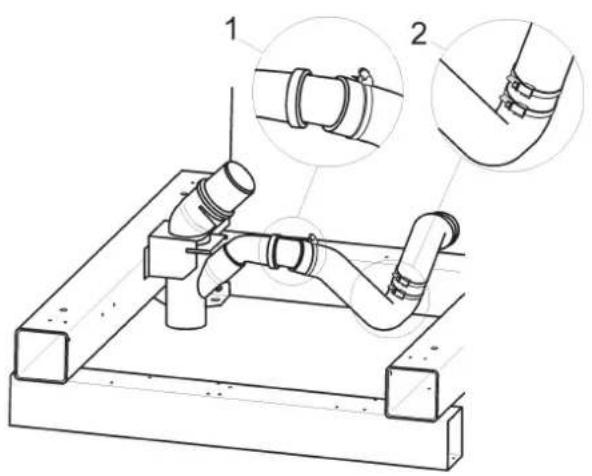
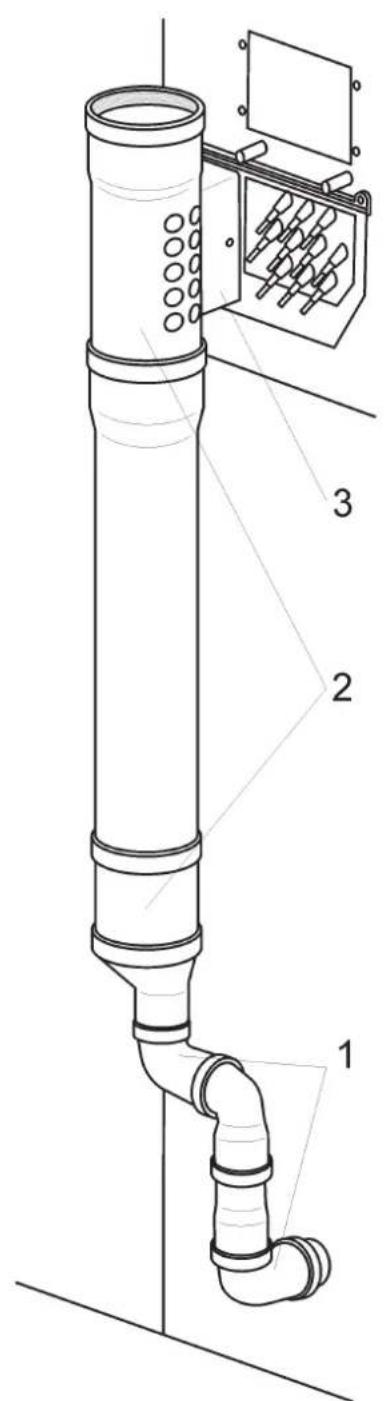
-Fig.10:Pipecombination
- Disconnect the machine from the electrical mains and ensure power cannot be switched on again in error.
-Removethesoiledsidecasingandtheleftsidecasingpanels.
Connect the branch pipe 75 × 50, 45^ , Fig. 2, Pos. 1, with the pipe bend 50 × 45^ , Fig. 2, Pos. 2, and slide them into position on the fixingbracketonthemachinedrainpipe.
Fit hose I and hose II on the connection piece, Fig. 3, Pos. 1, slide the parts fully together and fit the hose clips SGL 50-70. For the finalfittingposition,seeFig.5.
Note
Tosimplifydrainremoval/fitting,ensurethatthehoseclipsSGL50-70facetowardstheleftsidecasing.
-Fittthereinforcingring.Fig.4,Pos.1,inthepipebendhosefixing.
Fit the pre assembled hose I and II assembly, Fig. 4, Pos. 2, on the pipe bend hose fixing and fit a hose clip SGL 50-70. For the final fittingposition,seeFig.5.
Note
Tosimplifydrainremoval/fitting,ensurethatthehoseclipsSGL50-70facetowardstheleftsidecasing.
-Slidethepipebendhosefasteningintothepipebend50x45°,Fig.5,Pos.1.
-Fitconnectionpiece1,Fig.6,Pos.1,inhosel.
- Attach the holding plate, Fig. 6, Pos. 2, to the chassis with 2 raised-head screws CE M6 x 16. Use the existing holes in the chassis.
Screwconnectionpiece1andhoselwithahoseclipSGL50-70totheholdingplate.
-Fitconnectionpiece2,Fig.6,Pos.3,intoconnectionpiece1.
-Breakoutthepre-cutpieceinthesidecasing.
-Deburrthehole.
-Fitheleleftsidecasing.Fig.7.
Carefully clean and dry the mixer box around the vent, Fig. 8, Pos. 1, (hatched area) before fitting the foam adhesive tape to ensure thatitisattachedsecurely.
- When sticking the adhesive tape in place, start at the top in the middle, Fig. 8, Pos. 2. Then apply the tape in the direction of the arrowaroundtheventcollar.
Depending on the on-site conditions, prepare the existing vent system. For example cut the pipe pieces to size and fit them together, Fig.9,Pos.2,Pos.3.
-Fittheadapter,Fig.9,Pos.1,onthecollarofthesudscontainervent.
- Through the holes in the adapter, drill 2.5 mm dia. holes on the left and right in the suds container vent collar, Fig. 9, Pos. 4.
Pre assemble the pipe bend combination, Fig. 10, Pos. 1, consisting of 3 × bend 50 × 87 and 1 × bend 50 × 100 and fit it on connection2onthesidepanel.
Pre assemble the pipe combination, Fig. 10, Pos. 2, consisting of 1 x sleeve 110, 1 x pipe 110 x 50, 1 x pipe 110 x 500 and adapter for vapour/foamdissipation.
Fit the pre assembled pipe combination, Fig. 10, Pos. 2, on the pipe bend combination, Fig. 10, Pos. 1, and the suds container vent collar, Fig.10,Pos.3.
- Fasten the adapter to the vent collar with the two 4 × 15 ~mm raised-head screws provided, Fig. 9, Pos. 4.
Connect the adapter to the on-site vent system. If the vent connection, Fig. 9, Pos. 2, is not being used, the appropriate opening must be closed with a stopper. Thesmal openings (10 eachontherighttandleaf) in the headaptemust remain open.
-Carryoutatestrunandcheckthevapour/foamdissipationsystemforleaks.
-Refitthesidecasingonthesoiledside
-Carryoutappropriateelectricalsafetychecks.
-Reconnectthemachinetotheelectricmainssupply.
en
fr
Piècesnecessaires
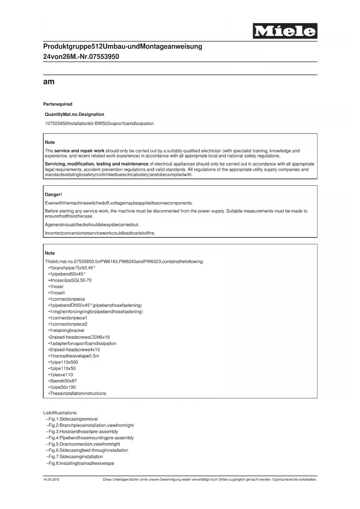
This service and repair work should only be carried out by a suitably qualified electrician (with specialist training, knowledge and experience, and recent related work experience) in accordance with all appropriate local and national safety regulations.
Servicing, modification, testing and maintenance of electrical appliances should only be carried out in accordance with all appropriate legal requirements, accident prevention regulations and valid standards. All regulations of the appropriate utility supply companies and standardsrelatingto safety(notlimitedtoelectricalsafety)aretobecompliedwith.
Danger!
Evenwiththemachineswitchedoff,voltagemaybeappliedtosomecomponents.
Before starting any service work, the machine must be disconnected from the power supply. Suitable measurements must be made to ensure that this is the case.
Ageneralvisualcheckshouldalwaysbocarriedout.
Incorrectconversionorserviceworkcouldleadtoriskoffire.
Note
Thiskit,mat.no.07555850,forPW6163,PW6243andPW6323,containsthe following:
-1branchpipe75x50,45°
-1pipebend50x45°
4hoseclipsSGL50-70
-1hosel
-1hosell
-1connectionpiece
· 1 pipebendDN50x45°(pipebendhosefastening)
-1 ring(reinforcingringforpipebendhosefastening)
-1connectionpiece1
-1connectionpiece2
-1retainingbracket
-2raised-headscrewsCEM6x16
-1adapterforvapor/foamdissipation
2raised-headscrews4x15
-1foamadhesivetape0.5m
-1pipe110x500
-1pipe110x50
1sleeve110
-3bends50x87
-1pipe50x100
Theseinstallationinstructions
Listofillustrations:
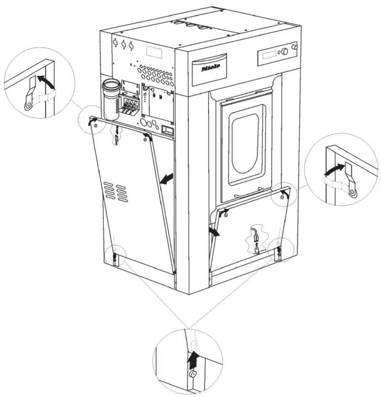
Fig.1:Sidecasingremoval
Fig.2: Branchpieceinstallation, viewfromright
Fig.3:Hoselandhosellpre-assembly
Fig.4:Pipebendhosemountingpre-assembly
Fig.5:Drainconnection,viewfromright
Fig.6:Sidecasingfeed-throughinstallation
Fig.7:Sidecasingsinstallation
-Fig.8:Installingfoamadhesivetape
-Fig.9:Installing,drillingandfasteningthevaporandfoamdissipationadapter
-Fig.10:Pipecombination
- Disconnect the machine from the electrical supply and ensure that power cannot be switched on again in error.
-Removethesoiled-sidecasingandtheleftsidecasingpanels.
Connect the branch pipe 75 × 50, 45^ (Fig. 2, Pos. 1) to the pipe bend 50 × 45^ (Fig. 2, Pos. 2) and slide them into position on the mountingbracketonthemachinedrainpipe.
Install hose I and hose II on the connection piece (Fig. 3, Pos. 1), slide the parts fully together and install the SGL 50-70 hose clips. Forthefinalinstallationposition,seeFig.5.
Note
Tosimplifydrainremoval/installation,ensurethatthehoseclipsfacetowardstheleftsidecasing.
-Installthereinforcingring(Fig.4,Pos.1)inthepipebendhoseassembly.
Install the hose I and II assembly (Fig. 4, Pos. 2) on the pipe bend hose assembly and install a hose clip0. For the final installation position,seeFig.5
Note
Tosimplifydrainremoval/installation,ensurethatthehoeseclipsfacetowardstheleftsidecasing.
-Slidethepipebendhosefasteningintothepipebend50x45°,Fig.5,Pos.1.
-Installconnectionpiece1(Fig.6,Pos.1)inhosel.
- Attach the mounting bracket (Fig. 6, Pos. 2) to the chassis with 2 raised-head screws. Use the existing holes in the chassis.
-Screwconnectionpiece1andhoseltothemountingbracketwithahoseclip.
-Installconnectionpiece2(Fig.6,Pos.3)inconnectionpiece1.
-Breakoutthepre-cutpieceinthesidecasing.
-Deburrthehole.
-Installthelefteasidecasing,Fig.7
Carefully clean and dry the mixer box around the vent (Fig. 8, Pos. 1, hatched area) before installing the foam adhesive tape to ensure that it is attached securely.
- When sticking the adhesive tape in place, start at the top in the middle, Fig. 8, Pos. 2. Then apply the tape in the direction of the arrowaroundtheventcollar.
Depending on the on-site conditions, prepare the existing vent system. For example, cut the pipe pieces to size and fit them together, Fig.9,Pos.2,Pos.3.
-Installheadapter(Fig.9,Pos.1)onthecollarofthesudscostainervent.
- Through the holes in the adapter, drill 2.5 mm dia. holes on the left and right in the suds container vent collar, Fig. 9, Pos. 4.
Pre-assemble the pipe bend combination (Fig. 10, Pos. 1), consisting of three 50 × 87 bends and one 50 × 100 bend and install it on connection2onthesidepanel.
Pre-assemble the pipe combination (Fig. 10, Pos. 2), consisting of one 110 sleeve, one 110 × 50 pipe, one 110 × 500 pipe and adapter forvapor/foamdissipation.
Install the pre-assembled pipe combination (Fig. 10, Pos. 2) on the pipe bend combination (Fig. 10, Pos. 1) and the suds container ventcollar(Fig.10,Pos.3).
- Fasten the adapter to the vent collar with the two 4 × 15 ~mm raised-head screws provided, Fig. 9, Pos. 4.
Connect the adapter to the on-site vent system. If the vent connection (Fig. 9, Pos. 2) is not being used, the appropriate opening must be closed with a stopper. Thesmal openings (10 eachontherighttandleft) in the headapter must remain open.
-Carryoutatestrunandcheckthevapor/foamdissipationsystemforleaks.
-Reinstallthesidecasingonthesoiledside.
-Carryoutappropriateelectricalsafetychecks.
-Reconnectthemachinetotheelectricalsupply.