
DJN161 - Scissors MAKITA - Free user manual and instructions
Find the device manual for free DJN161 MAKITA in PDF.

| Product Type | Cordless Nibbler |
| Brand | Makita |
| Model | DJN161 |
| Cutting capacities (steel 400 N/mm²) | 1.6 mm max |
| Cutting capacities (steel 600 N/mm²) | 1.2 mm max |
| Cutting capacities (aluminum 200 N/mm²) | 2.5 mm max |
| Minimum cutting radius (outer edge) | 50 mm |
| Minimum cutting radius (inner edge) | 45 mm |
| Number of strokes per minute | 1,900 min⁻¹ |
| Total length | 313 mm |
| Net weight | 1.9 - 2.3 kg |
| Nominal voltage | 18 V DC |
| Compatible batteries | BL1815N, BL1820, BL1820B, BL1830, BL1830B, BL1840, BL1840B, BL1850, BL1850B, BL1860B |
| Compatible chargers | DC18RC, DC18RD, DC18RE, DC18SD, DC18SE, DC18SF |
| Sound pressure level | 96 dB(A) |
| Sound power level | 104 dB(A) |
| Vibration emission (sheet metal cutting) | 6.5 m/s² |
| Main applications | Cutting of sheet metal and stainless steel sheet |
| Power supply | 18 V lithium-ion battery |
| Maintenance | Brush replacement, lubrication of punch and die |
| Safety | Overload protection, accidental restart prevention, safety instructions provided |
| Spare parts available | Die, punch, hex key, 32 mm wrench, brushes, authentic Makita batteries and chargers |
Frequently Asked Questions - DJN161 MAKITA
User questions about DJN161 MAKITA
0 question about this device. Answer the ones you know or ask your own.
Ask a new question about this device
Download the instructions for your Scissors in PDF format for free! Find your manual DJN161 - MAKITA and take your electronic device back in hand. On this page are published all the documents necessary for the use of your device. DJN161 by MAKITA.
USER MANUAL DJN161 MAKITA
GB Cordless Nibbler Instruction Manual
natural_image
Technical line drawing of a handheld electric drill bit (no text or symbols)
013273 012128
1
015659 013275 4
3
004775 013276
5
7
013277 004779
8
9
013274
10
004781
11 12
004782
natural_image
Line drawing of a hand using a power drill to press or install a flat sheet on a workbench (no text or symbols)013278
natural_image
Illustration of a hand using a power tool to lift a circular object on a surface (no text or symbols)13
013279
flowchart
graph TD
    A["Component 23"] --> B["Component 24"]
    B --> C["Component 25"]
    C --> D["Bottom Diagram"]
    style A fill:#f9f,stroke:#333
    style B fill:#f9f,stroke:#333
    style C fill:#f9f,stroke:#333
    style D fill:#ccf,stroke:#333
14
013280
15 16
001145004791
17 18
013281 013282
ENGLISH (Original instructions)
| Explanation of general view | ||
| 1 Button | 12 Gauge for cutting mild steel: | 24 Cutting at an angle to grooves |
| 2 Red indicator | 1.6 mm (1/16") | 25 Cutting perpendicular to grooves |
| 3 Battery cartridge | 13 Notch | |
| 4 Star marking | 14 Slide switch | 26 From the side view |
| 5 Indicator lamps | 15 Indicating lamp | 27 Corrugated or trapezoidal sheet metal |
| 6 Check button | 16 Die | |
| 7 Die holder | 17 Bolts | 28 Cutting head should be at a right angle (90°) to cutting surface. |
| 8 Lock nut | 18 Hex wrench | |
| 9 Loosen | 19 Punch | |
| 10 Wrench | 20 Punch holder | 29 Limit mark |
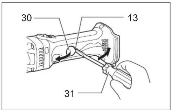
| 11 Gauge for cutting stainless: | 21 Screw | 30 Holder cap cover |
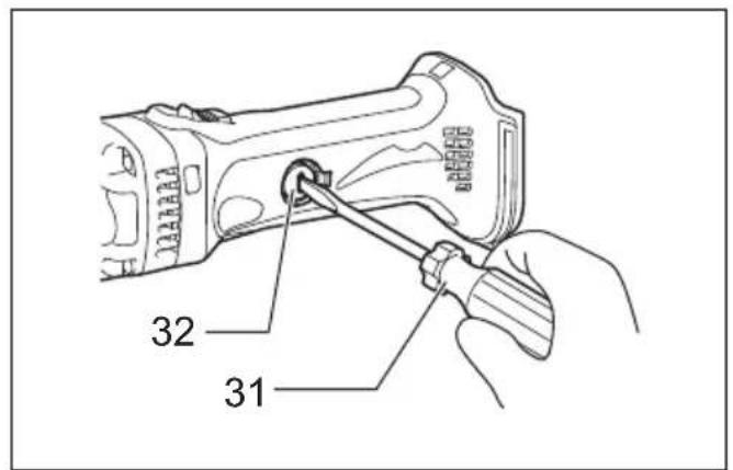
| 1.2 mm (3/64") | 22 Tighten | 31 Screwdriver |
| 23 From the top view | 32 Brush holder cap |
SPECIFICATIONS
| Model DJN161 | ||
| Max. cutting capacities | Steel up to 400 N/mm2 | 1.6 mm/16 ga |
| Steel up to 600 N/mm2 | 1.2 mm/18 ga | |
| Aluminum up to 200 N/mm2 | 2.5 mm/12 ga | |
| Min. cutting radius | Outside edge 50 mm | |
| Inside edge 45 mm | ||
| Strokes per minute (min-1) | 1 | |
| Overall length 313 mm | ||
| Net weight 1.9 – 2.3 kg | ||
| Rated voltage D.C. 18 V | ||
- Due to our continuing program of research and development, the specifications herein are subject to change without notice.
- Specifications may differ from country to country.
- The weight may differ depending on the attachment(s), including the battery cartridge. The lightest and heaviest combination, according to EPTA-Procedure 01/2014, are shown in the table.
Applicable battery cartridge and charger
| Battery cartridge | BL1815N / BL1820 / BL1820B / BL1830 / BL1830B / BL1840 / BL1840B / BL1850 / BL1850B / BL1860B |
| Charger | DC18RC / DC18RD / DC18RE / DC18SD / DC18SE / DC18SF |
- Some of the battery cartridges and chargers listed above may not be available depending on your region of residence.
WARNING: Only use the battery cartridges and chargers listed above. Use of any other battery cartridges and chargers may cause injury and/or fire.
ENE037-1
GEA010-2
Intended use
The tool is intended for cutting sheet steel and stainless sheet steel.
General Power Tool Safety Warnings
WARNING Read all safety warnings, instructions, illustrations and specifications provided with this power tool. Failure to follow all instructions listed below may result in electric shock, fire and/or serious injury.
Save all warnings and instructions for future reference.
The term “power tool” in the warnings refers to your mains-operated (corded) power tool or battery-operated (cordless) power tool.
NIBBLER SAFETY WARNINGS
- Hold the tool firmly.
- Secure the workpiece firmly.
- Keep hands away from moving parts.
- Edges and chips of the workpiece are sharp. Wear gloves. It is also recommended that you put on thickly bottomed shoes to prevent injury.
- Do not put the tool on the chips of the workpiece. Otherwise it can cause damage and trouble on the tool.
- Do not leave the tool running. Operate the tool only when hand-held.
- Always be sure you have a firm footing. Be sure no one is below when using the tool in high locations.
- Do not touch the punch, die or the workpiece immediately after operation; they may be extremely hot and could burn your skin.
- Avoid cutting electrical wires. It can cause serious accident by electric shock.
SAVE THESE INSTRUCTIONS.
WARNING:
DO NOT let comfort or familiarity with product (gained from repeated use) replace strict adherence to safety rules for the subject product. MISUSE or failure to follow the safety rules stated in this instruction manual may cause serious personal injury.
ENC007-12
IMPORTANT SAFETY INSTRUCTIONS FOR BATTERY CARTRIDGE
- Before using battery cartridge, read all instructions and cautionary markings on (1) battery charger, (2) battery, and (3) product using battery.
- Do not disassemble battery cartridge.
- If operating time has become excessively shorter, stop operating immediately. It may result in a risk of overheating, possible burns and even an explosion.
- If electrolyte gets into your eyes, rinse them out with clear water and seek medical attention right away. It may result in loss of your eyesight.
- Do not short the battery cartridge:
(1) Do not touch the terminals with any conductive material.
(2) Avoid storing battery cartridge in a container with other metal objects such as nails, coins, etc.
(3) Do not expose battery cartridge to water or rain.
A battery short can cause a large current flow, overheating, possible burns and even a breakdown.
- Do not store the tool and battery cartridge in locations where the temperature may reach or exceed 50^ C ( 122^ F).
- Do not incinerate the battery cartridge even if it is severely damaged or is completely worn out. The battery cartridge can explode in a fire.
- Be careful not to drop or strike battery.
-
Do not use a damaged battery.
-
The contained lithium-ion batteries are subject to the Dangerous Goods Legislation requirements.
For commercial transports e.g. by third parties, forwarding agents, special requirement on packaging and labeling must be observed.
For preparation of the item being shipped, consulting an expert for hazardous material is required. Please also observe possibly more detailed national regulations.
Tape or mask off open contacts and pack up the battery in such a manner that it cannot move around in the packaging.
- Follow your local regulations relating to disposal of battery.
- Use the batteries only with the products specified by Makita. Installing the batteries to non-compliant products may result in a fire, excessive heat, explosion, or leak of electrolyte.
SAVE THESE INSTRUCTIONS.
CAUTION: Only use genuine Makita batteries. Use of non-genuine Makita batteries, or batteries that have been altered, may result in the battery bursting causing fires, personal injury and damage. It will also void the Makita warranty for the Makita tool and charger.
Tips for maintaining maximum battery life
- Charge the battery cartridge before completely discharged. Always stop tool operation and charge the battery cartridge when you notice less tool power.
- Never recharge a fully charged battery cartridge. Overcharging shortens the battery service life.
- Charge the battery cartridge with room temperature at 10^ C - 40^ C ( 50^ F - 104^ F). Let a hot battery cartridge cool down before charging it.
- Charge the battery cartridge if you do not use it for a long period (more than six months).
FUNCTIONAL DESCRIPTION
CAUTION:
- Always be sure that the tool is switched off and the battery cartridge is removed before adjusting or checking function on the tool.
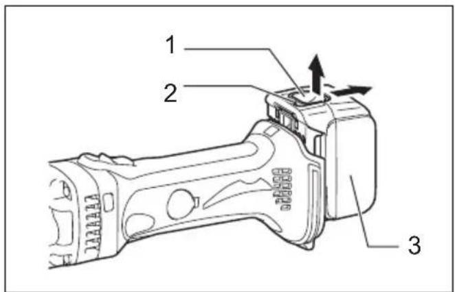
Installing or removing battery cartridge (Fig. 1)
CAUTION:
- Always switch off the tool before installing or removing of the battery cartridge.
- Hold the tool and the battery cartridge firmly when installing or removing battery cartridge. Failure to hold the tool and the battery cartridge firmly may cause them to slip off your hands and result in damage to the tool and battery cartridge and a personal injury.
To remove the battery cartridge, slide it from the tool while sliding the button on the front of the cartridge.
To install the battery cartridge, align the tongue on the battery cartridge with the groove in the housing and slip it into place. Insert it all the way until it locks in place with a little click. If you can see the red indicator on the upper side of the button, it is not locked completely.

CAUTION:
• Always install the battery cartridge fully until the red indicator cannot be seen. If not, it may accidentally fall out of the tool, causing injury to you or someone around you.
- Do not install the battery cartridge forcibly. If the cartridge does not slide in easily, it is not being inserted correctly.
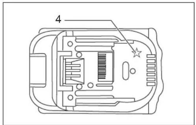
Battery protection system (Fig. 2)
The tool is equipped with a battery protection system. This system automatically cuts off power to the motor to extend battery life.
The tool will automatically stop during operation if the tool and/or battery are placed under one of the following conditions:
• Overloaded:
The tool is operated in a manner that causes it to draw an abnormally high current.
In this situation, turn the tool off and stop the application that caused the tool to become overloaded. Then turn the tool on to restart.
If the tool does not start, the battery is overheated. In this situation, let the battery cool before turning the tool on again.
- Low battery voltage:
The remaining battery capacity is too low and the tool will not operate. In this situation, remove and recharge the battery.
NOTE:
- The overheat protection works only with a battery cartridge with a star mark.
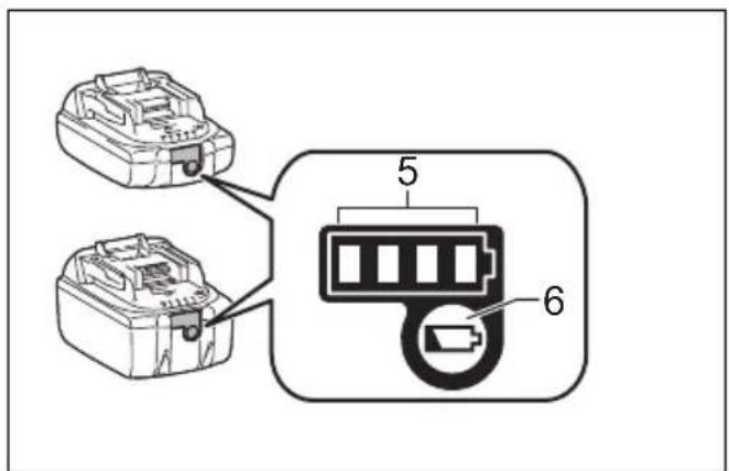
Indicating the remaining battery capacity (Fig. 3) Only for battery cartridges with the indicator
Press the check button on the battery cartridge to indicate the remaining battery capacity. The indicator lamps light up for few seconds.
| Indicator lamps | Remaining Capacity | ||
| Lighted Off Blinking | |||
| 75% to 100% | |||
| 50% to 75% | |||
| 25% to 50% | |||
| 0% to 25% | |||
| Charge the battery. | |||
| The battery may have malfunctioned. | |||
015658
NOTE:
- Depending on the conditions of use and the ambient temperature, the indication may differ slightly from the actual capacity.
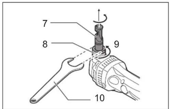
Changing the die position (Fig. 4)
The die holder position can be changed 360°. To change it, proceed as follows.
- Loosen the lock nut with the wrench provided.
- Pull the die holder slightly and turn it to the desired position for operation.
- Tighten the lock nut to secure the die holder in the desired position.
There are four positive stops at 90^ each: 0^ , 90^ left and right and 180^ . To position the die to any of these positive stops:
-
Loosen the lock nut with the wrench provided.
-
Pull the die holder slightly and depress lightly while turning it to the desired position. The die holder will lock into one of the positive stop positions as desired.
-
Turn the die holder slightly to make sure that it is positively locked into position.
-
Tighten the lock nut to secure the die holder.
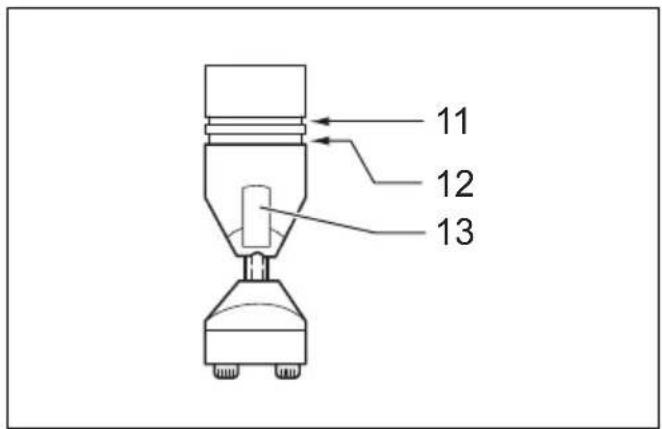
Permissible cutting thickness (Fig. 5)
The thickness of material to be cut depends upon the tensile strength of the material itself. The groove on the die holder acts as a thickness gauge for allowable cutting thickness. Do not attempt to cut any material which will not fit into this groove.
Cutting line
The notch in the die holder indicates your cutting line. Its width is equal to the cutting width. Align the notch to the cutting line on the workpiece when cutting.
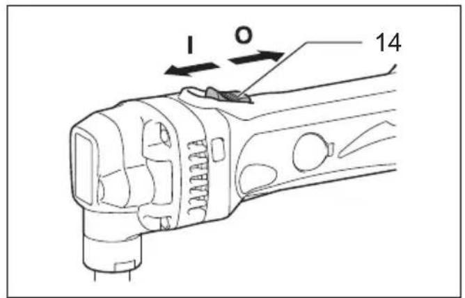
Switch action (Fig. 6)

CAUTION:
- Before inserting the battery cartridge into the tool, always check to see that the slide switch actuates properly and returns to the "OFF" position when the rear of the slide switch is depressed.
- Switch can be locked in "ON" position for ease of operator comfort during extended use. Apply caution when locking tool in "ON" position and maintain firm grasp on tool.
To start the tool, slide the slide switch toward the "I (ON)" position. For continuous operation, press the front of the slide switch to lock it.
To stop the tool, press the rear of the slide switch, then slide it toward the "O (OFF)" position.
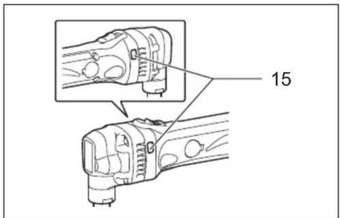
Indication lamp with multi function (Fig. 7)
Indication lamps are located in two positions.
- Battery cartridge replacing signal
- When the battery power is almost used up during operation, the red lamp lights up and the tool stops immediately. Replace the battery with fully charged one when the red lamp lights up.
- Accidental re-start preventive function
- Even if the battery cartridge is inserted on the tool with the slide switch in the "I (ON)" position, the tool does not start. At this time, the lamp flickers slowly and this shows that the accidental re-start preventive function is at work.
- To start the tool, first slide the slide switch toward the "O (OFF)" position and then slide it toward the "I (ON)" position.
ASSEMBLY
CAUTION:
- Always be sure that the tool is switched off and the battery cartridge is removed before carrying out any work on the tool.
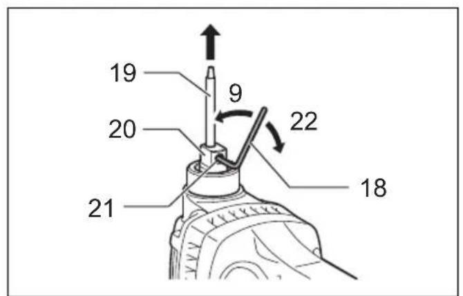
Removing or installing the punch and die (Fig. 8, 9, 10 & 11)
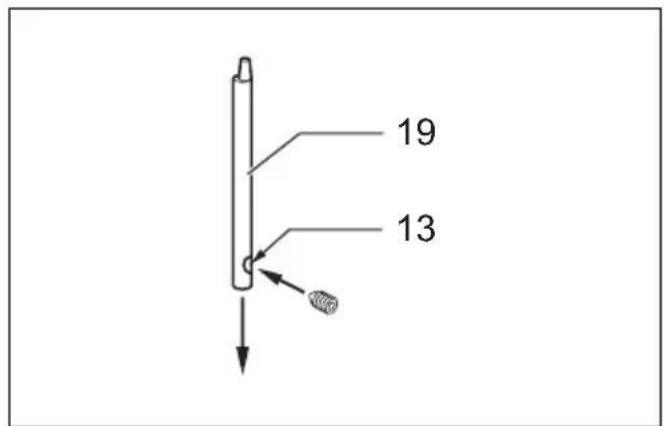
Always replace the punch and die as a set. To remove the punch and die, loosen the lock nut with the wrench. Remove the die holder from the tool. Use the hex wrench to loosen the bolts which secure the die. Remove the die from the die holder.
Use the hex wrench to loosen the screw which secures the punch. Pull the punch out of the punch holder.
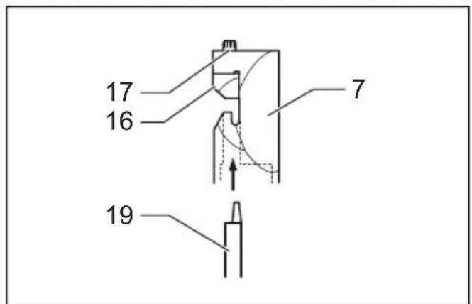
To install the punch and die, insert the punch into the punch holder so that the notch in the punch faces toward the screw. Tighten the screw to secure the punch. Install the die on the die holder. Tighten the bolts to secure the die.
Then install the die holder on the tool so that the punch is inserted through the hole in the die holder. Tighten the lock nut to secure the die holder. After replacing the punch and die, lubricate them with machine oil and run the tool for a while.
OPERATION
Pre-lubrication
Coat the cutting line with machine oil to increase the punch and die service life. This is particularly important when cutting aluminum.
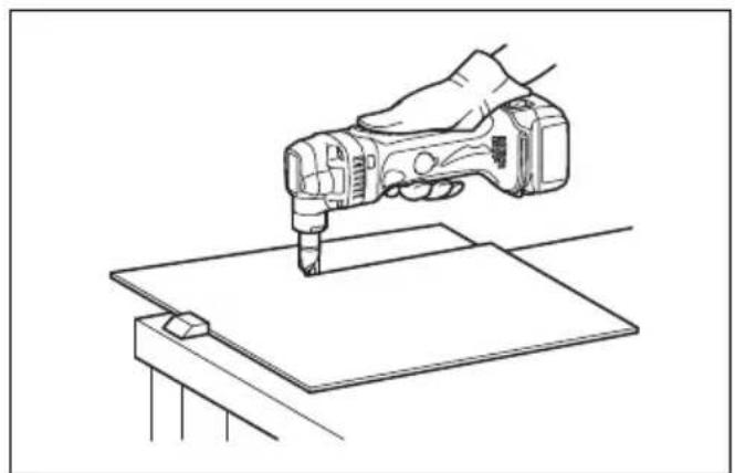
Cutting method (Fig. 12)
Hold the tool so that the cutting head is at a right angle (90°) to the workpiece being cut. Move the tool gently in the cutting direction.
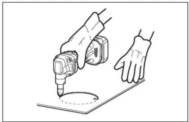
Cutouts (Fig. 13)
Cutouts can be done by first opening a round hole over 21 mm in diameter which the cutting head can be inserted into.
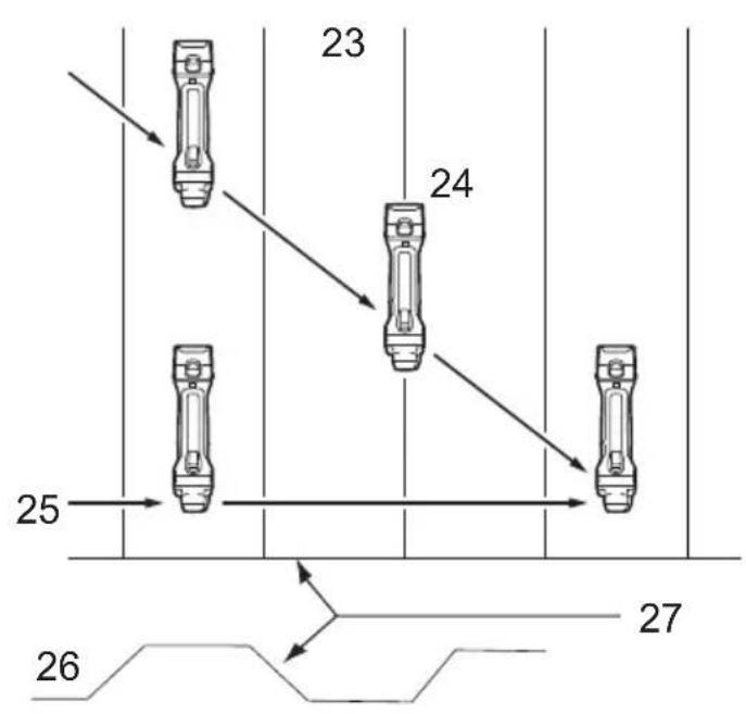
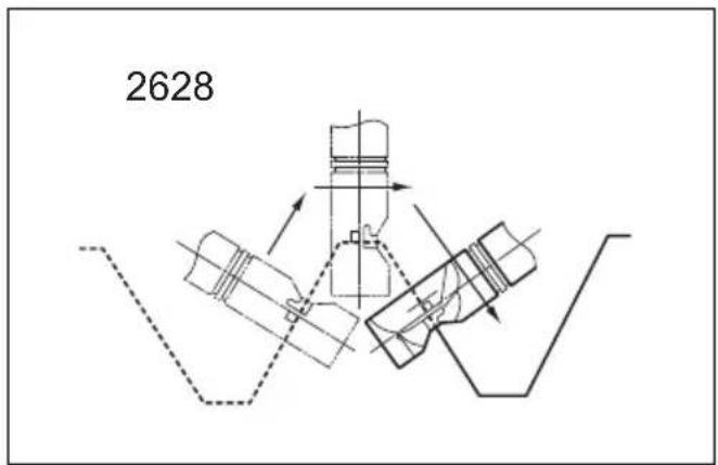
Cutting the corrugated or trapezoidal sheet metals (Fig. 14 & 15)
Set the die position so that the die faces the cutting direction either when cutting at an angle or perpendicular go grooves in corrugated or trapezoidal sheet metals.
Always hold the tool body parallel to the grooves with the cutting head at a right angle (90°) to the cutting surface as shown in the figure.
MAINTENANCE
CAUTION:
- Always be sure that the tool is switched off and the battery cartridge is removed before attempting to perform inspection or maintenance.
- Never use gasoline, benzine, thinner, alcohol or the like. Discoloration, deformation or cracks may result.
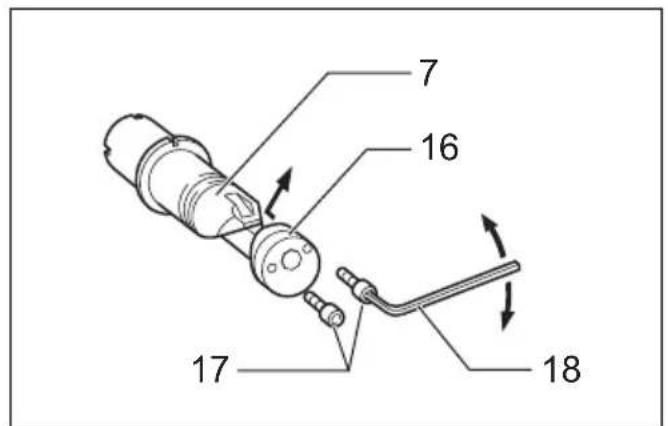
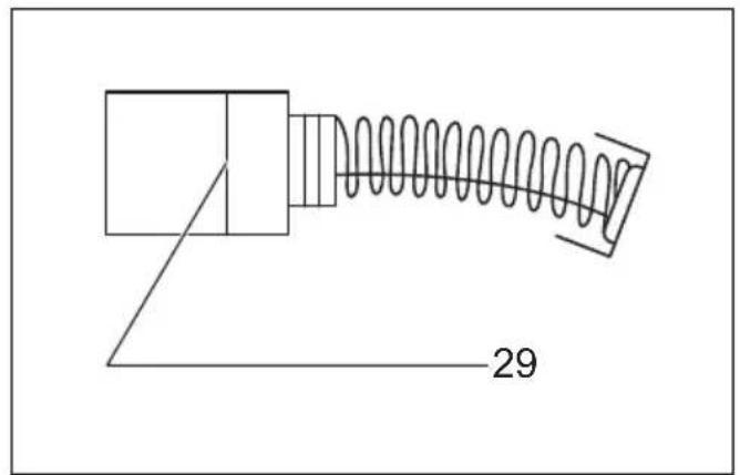
Replacing carbon brushes (Fig. 16, 17 & 18)
Remove and check the carbon brushes regularly. Replace when they wear down to the limit mark. Keep the carbon brushes clean and free to slip in the holders. Both carbon brushes should be replaced at the same time. Use only identical carbon brushes.
Insert the top end of slotted bit screwdriver into the notch in the tool and remove the holder cap cover by lifting it up.
Use a screwdriver to remove the brush holder caps. Take out the worn carbon brushes, insert the new ones and secure the brush holder caps.
Reinstall the holder cap cover on the tool.
To maintain product SAFETY and RELIABILITY, repairs, any other maintenance or adjustment should be performed by Makita Authorized Service Centers, always using Makita replacement parts.
OPTIONAL ACCESSORIES
CAUTION:
- These accessories or attachments are recommended for use with your Makita tool specified in this manual. The use of any other accessories or attachments might present a risk of injury to persons. Only use accessory or attachment for its stated purpose.
If you need any assistance for more details regarding these accessories, ask your local Makita Service Center.
• Die
- Punch
• Hex wrench
- Wrench 32
- Makita genuine battery and charger
NOTE:
- Some items in the list may be included in the tool package as standard accessories. They may differ from country to country.
ENG905-1
Noise
The typical A-weighted noise level determined according to EN62841-2-8:
Sound pressure level ( L_pA ): 96 dB(A)
Sound power level ( L_WA ): 104 dB(A)
Uncertainty (K): 3 dB(A)
ENG907-1
NOTE:
- The declared noise emission value(s) has been measured in accordance with a standard test method and may be used for comparing one tool with another.
- The declared noise emission value(s) may also be used in a preliminary assessment of exposure.
WARNING:
- Wear ear protection.
- The noise emission during actual use of the power tool can differ from the declared value(s) depending on the ways in which the tool is used especially what kind of workpiece is processed.
- Be sure to identify safety measures to protect the operator that are based on an estimation of exposure in the actual conditions of use (taking account of all parts of the operating cycle such as the times when the tool is switched off and when it is running idle in addition to the trigger time).
Vibration
The vibration total value (tri-axial vector sum) determined according to EN62841-2-8:
Work mode: cutting sheet metal
Vibration emission ( a_h ): 6.5 m/s ^2
Uncertainty (K): 1.5 m/s²
ENG901-2
NOTE:
- The declared vibration total value(s) has been measured in accordance with a standard test method and may be used for comparing one tool with another.
- The declared vibration total value(s) may also be used in a preliminary assessment of exposure.

WARNING:
- The vibration emission during actual use of the power tool can differ from the declared value(s) depending on the ways in which the tool is used especially what kind of workpiece is processed.
- Be sure to identify safety measures to protect the operator that are based on an estimation of exposure in the actual conditions of use (taking account of all parts of the operating cycle such as the times when the tool is switched off and when it is running idle in addition to the trigger time).
DECLARATIONS OF CONFORMITY
For European countries only
The Declarations of conformity are included in Annex A to this instruction manual.
Descriptif
DÉCLARATIONS DE CONFORMITÉ
OPTIONELE ACCESSOIRES
LET OP:

- Intended use
- General Power Tool Safety Warnings
- Save all warnings and instructions for future reference.
- NIBBLER SAFETY WARNINGS
- SAVE THESE INSTRUCTIONS.
- WARNING:
- IMPORTANT SAFETY INSTRUCTIONS FOR BATTERY CARTRIDGE
- Tips for maintaining maximum battery life
- FUNCTIONAL DESCRIPTION
- CAUTION:
- Installing or removing battery cartridge (Fig. 1)
- Battery protection system (Fig. 2)
- NOTE:
- Indicating the remaining battery capacity (Fig. 3) Only for battery cartridges with the indicator
- 015658
- Changing the die position (Fig. 4)
- Permissible cutting thickness (Fig. 5)
- Cutting line
- Switch action (Fig. 6)
- Indication lamp with multi function (Fig. 7)
- - Battery cartridge replacing signal
- - Accidental re-start preventive function
- ASSEMBLY
- Removing or installing the punch and die (Fig. 8, 9, 10 & 11)
- OPERATION
- Pre-lubrication
- Cutting method (Fig. 12)
- Cutouts (Fig. 13)
- Cutting the corrugated or trapezoidal sheet metals (Fig. 14 & 15)
- MAINTENANCE
- Replacing carbon brushes (Fig. 16, 17 & 18)
- OPTIONAL ACCESSORIES
- Noise
- Vibration
- DECLARATIONS OF CONFORMITY
- For European countries only
- DÉCLARATIONS DE CONFORMITÉ
- OPTIONELE ACCESSOIRES
- LET OP:
Brand : MAKITA
Model : DJN161
Category : Scissors