BJS130RFJ - Scissors MAKITA - Free user manual and instructions
Find the device manual for free BJS130RFJ MAKITA in PDF.

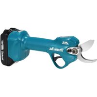
| Product Type | Cordless metal shear |
| Brand | Makita |
| Model | BJS130RFJ |
| Max cutting capacity (steel up to 400 N/mm²) | 1.3 mm (18 ga.) |
| Max cutting capacity (stainless steel up to 600 N/mm²) | 1.0 mm (20 ga.) |
| Strokes per minute (min⁻¹) | 2800 |
| Overall length | 350 mm |
| Net weight | 2.4 kg |
| Rated voltage | 18 V DC |
| Battery type | Lithium-ion (compatible with Makita 18 V) |
| Main applications | Cutting metal sheets and stainless steel |
| Routine maintenance | Blade lubrication, replacement of carbon brushes |
| Recommended safety | Wear gloves, safety glasses, dust mask |
| Common spare parts | Center blade, side blades D and G, carbon brushes, hex key |
| Sound pressure level (LpA) | 74 dB(A) |
| Vibration level (metal cutting) | 5.5 m/s² (uncertainty 1.5 m/s²) |
Frequently Asked Questions - BJS130RFJ MAKITA
User questions about BJS130RFJ MAKITA
0 question about this device. Answer the ones you know or ask your own.
Ask a new question about this device
Download the instructions for your Scissors in PDF format for free! Find your manual BJS130RFJ - MAKITA and take your electronic device back in hand. On this page are published all the documents necessary for the use of your device. BJS130RFJ by MAKITA.
USER MANUAL BJS130RFJ MAKITA
GB Cordless Metal Shear
Instruction Manual
Explanation of general view
| 1 Red part | 11 Side blade R | 21 Hex socket head bolt |
| 2 B u t t o n | 12 Sleeve | 22 Barrel |
| 3 Battery cartridge | 13 Tighten | 23 Front cover |
| 4 Trigger-lock button | 14 Hook | 24 Spring |
| 5 Switch trigger | 15 Side blade | 25 Arm |
| 6 Cutting head | 16 Side blade surface | 26 Recessed part |
| 7 Screws | 17 Workpiece | 27 Carbon brush cap |
| 8 Hex wrench | 18 Lubricate | 28 Hole |
| 9 Side blade L | 19 Limit mark | |
| 10 Center blade | 20 Holder |
SPECIFICATIONS
Model BJS130
| Max. cutting capacities Steel up to 400 N/mm2 | 1.3 mm (18 ga.) |
| Stainless Steel up to 600 N/mm2 | 1.0 mm (20 ga.) |
| Strokes per minute (min-1) | 2,800 |
| Overall length | 350 mm |
| Net weight | 2.4 kg |
| Rated voltage | D.C. 18 V |
- Due to our continuing program of research and development, the specifications herein are subject to change without notice.
- Note: Specifications may differ from country to country.
Intended use
The tool is intended for cutting sheet metal and stainless sheet steel.
Safety hints
For your own safety, please refer to the enclosed safety instructions.
SPECIFIC SAFETY RULES
GEB032-1
DO NOT let comfort or familiarity with product (gained from repeated use) replace strict adherence to cement shear safety rules. If you use this power tool unsafely or incorrectly, you can suffer serious personal injury.
- Hold the tool firmly.
- Secure the workpiece firmly.
- Keep hands away from moving parts.
- Edges and chips of the workpiece are sharp. Wear gloves. It is also recommended that you put on thickly bottomed shoes to prevent injury.
- Do not put the tool on the chips of the workpiece. Otherwise it can cause damage and trouble on the tool.
- Do not leave the tool running. Operate the tool only when hand-held.
- Always be sure you have a firm footing. Be sure no one is below when using the tool in high locations.
- Do not touch the blade or the workpiece immediately after operation; they may be extremely hot and could burn your skin.
- Avoid cutting electrical wires. It can cause serious accident by electric shock.
-
Some material contains chemicals which may be toxic. Take caution to prevent dust inhalation and skin contact. Follow material supplier safety data.
-
Always use the correct dust mask/respirator for the material and application you are working with.
SAVE THESE INSTRUCTIONS.
WARNING:
MISUSE or failure to follow the safety rules stated in this instruction manual may cause serious personal injury.
IMPORTANT SAFETY INSTRUCTIONS
FOR BATTERY CARTRIDGE
ENC007-2
- Before using battery cartridge, read all instructions and cautionary markings on (1) battery charger, (2) battery, and (3) product using battery.
- Do not disassemble battery cartridge.
- If operating time has become excessively shorter, stop operating immediately. It may result in a risk of overheating, possible burns and even an explosion.
- If electrolyte gets into your eyes, rinse them out with clear water and seek medical attention right away. It may result in loss of your eyesight.
- Do not short the battery cartridge:
(1) Do not touch the terminals with any conductive material.
(2) Avoid storing battery cartridge in a container with other metal objects such as nails, coins, etc.
(3) Do not expose battery cartridge to water or rain.
A battery short can cause a large current flow, overheating, possible burns and even a breakdown.
- Do not store the tool and battery cartridge in locations where the temperature may reach or exceed 50^ (122^) .
- Do not incinerate the battery cartridge even if it is severely damaged or is completely worn out. The battery cartridge can explode in a fire.
- Be careful not to drop or strike battery.
SAVE THESE INSTRUCTIONS.
Tips for maintaining maximum battery life
- Charge the battery cartridge before completely discharged. Always stop tool operation and charge the battery cartridge when you notice less tool power.
- Never recharge a fully charged battery cartridge. Overcharging shortens the battery service life.
- Charge the battery cartridge with room temperature at 10^ - 40^ (50^ - 104^) . Let a hot battery cartridge cool down before charging it.
FUNCTIONAL DESCRIPTION
CAUTION:
- Always be sure that the tool is switched off and the battery cartridge is removed before adjusting or checking function on the tool.
Installing or removing battery cartridge (Fig. 1)
- Always switch off the tool before insertion or removal of the battery cartridge.
- To remove the battery cartridge, withdraw it from the tool while sliding the button on the front of the cartridge.
- To insert the battery cartridge, align the tongue on the battery cartridge with the groove in the housing and slip it into place. Always insert it all the way until it locks in place with a little click. If you can see the red part on the upper side of the button, it is not locked completely. Insert it fully until the red part cannot be seen. If not, it may accidentally fall out of the tool, causing injury to you or someone around you.
- Do not use force when inserting the battery cartridge. If the cartridge does not slide in easily, it is not being inserted correctly.
Switch action (Fig. 2)
CAUTION:
- Before inserting the battery cartridge into the tool, always check to see that the switch trigger actuates properly and returns to the "OFF" position when released.
- When not operating the tool, depress the trigger-lock button from B side to lock the switch trigger in the OFF position.
To prevent the switch trigger from accidentally pulled, the trigger-lock button is provided.
To start the tool, depress the trigger-lock button from A side and pull the switch trigger.
Release the switch trigger to stop. After use, always press in the trigger-lock button from B side.
ASSEMBLY
CAUTION:
- Always be sure that the tool is switched off and the battery cartridge is removed before adjusting or checking function on the tool.
Replacement of blades
CAUTION:
- Never remove the blades with bare hands. Wear gloves. Otherwise it can cause injury.
Removing cutting head (Fig. 3)
Use the hex wrench to loosen the three screws which secure the cutting head. Pull the cutting head straight out to remove it with turning it left and right alternately.
Removing shear blades (Fig. 4)
Remove the three screws which hold the cutting head. When removing the second screw, be careful not to fall the sleeve. Then the blades can be removed easily. When removing the blades, hold the blades and the sleeve so that they do not fall from the cutting head.
Installing shear blades (Fig. 5)
Install the sleeve and tighten the three screws after inserting the center blade, side blade L & R into the cutting head. In this process, the screw heads should be protruding 2 - 3mm from the cutting head surface.
If you will tighten the screws excessively, the cutting heads cannot be installed to the tool.
Installing cutting head (Fig. 6)
CAUTION:
- Secure the cutting head firmly. Otherwise it can rotate during operation and can cause serious injury.
Insert the cutting head into the tool with turning it left and right alternately. Then tighten the three screws with the hex wrench.
Hex wrench storage (Fig. 7)
When not in use, store the hex wrench as shown in the figure to keep it from being lost.
Carry hook (Fig. 8)
The carry hook is convenient for temporarily hooking the tool. It can be installed on either side of the tool.
When removing the carry hook, widen it by pressing its right ends ON BOTH SIDES in the directions of arrow (1) and raise it in the direction of the arrow (2).
OPERATION
CAUTION:
- Edges and chips of the workpiece are sharp. Wear gloves. Otherwise it can cause injury.
Secure the workpiece firmly. Move the tool forward keeping the side blades flush with the workpiece surface. (Fig. 9 & 10)
Adjusting shear blade (Fig. 11)
Adjust the side blade L so that the curl of waste material does not contact the cutting head or the workpiece. Use the hex wrench to loosen the three screws which hold the cutting head. Move the side blade L back and forth to adjust it. Then tighten the three screws with the hex wrench.
MAINTENANCE
CAUTION:
- Always be sure that the tool is switched off and the battery cartridge is removed before attempting to perform inspection or maintenance.
Lubrication (Fig. 12)
Before operation, lubricate the contact point of the center blade and the side blades R/L. And, also lubricate the point of the center blade near the cutting head. To keep good cutting performance, use lubricant from time to time during operation.
Replacing carbon brushes
Replace when they wear down to the limit mark. Keep the carbon brushes clean and free to slip in the holders.
Both carbon brushes should be replaced at the same time. Use only identical carbon brushes. (Fig. 13)
First remove the holder by unscrewing the hex socket head bolt. (Fig. 14)
Then loosen the hex socket head bolt that fastens the barrel and turn the barrel counterclockwise. (Fig. 15)
Use a screwdriver to remove two screws then remove the front cover. (Fig. 16)
Raise the arm part of the spring and then place it in the recessed part of the housing with a slotted bit screwdriver of slender shaft or the like. (Fig. 17)
Use pliers to remove the carbon brush caps of the carbon brushes. Take out the worn carbon brushes, insert the new ones and replace the carbon brush caps in reverse. (Fig. 18)
Make sure that the carbon brush caps have fit into the holes in brush holders securely. (Fig. 19)
Reinstall the front cover and tighten two screws securely.
To maintain product SAFETY and RELIABILITY, repairs, carbon brush inspection and replacement, any other maintenance or adjustment should be performed by Makita Authorized Service Centers, always using Makita replacement parts.
ACCESSIONS
CAUTION:
- These accessories or attachments are recommended for use with your Makita tool specified in this manual. The use of any other accessories or attachments might present a risk of injury to persons. Only use accessory or attachment for its stated purpose.
If you need any assistance for more details regarding these accessories, ask your local Makita service center.
Centerblade
- Side blade R
Sideblade L
- Hex wrench
- Various type of Makita genuine batteries and chargers
Descriptif
Lubrification (Fig. 12)
Nominate spanning. DC 18 V
Enavatoono0eTnoTe to npooTivo kaLumau KaU ophiTe kala tic duo biEc.
Tia Tnv diatnpnon Tnc A2AFAEIAZ kai AEIONIETIAZ TOU npoiovTOc, ENIOKeUc, EeYxoc KAI avtikataoTaon twv pKtpwv avtheta, onoiadnote aan ouvtponn npuOmuon, npenla va ekteLouvta ano Kevtpa EEuunpctnonc Epyoostaoiou n Kevtpa EeouioDOnueva ano Tnv MaKita, naVTOE tnv xpnouonoiOn avtaaakTuKwv MaKita.
EAPTMATA
PPOEOXH:
Auta ta eApntnata n npoaaptnata ouviotwvta yia xpno n e To epyaieio Makita nou nepiyapntke otic obnyies autc. H xpno ontodnone aawv eApntmuatwv n npoaaptnpatwv mnpoei va npokaleoi kivduvo tpaumatiou o atoua. Xpnoonoiite Ta eApntnata n npoaaptnata movo yia tvx npoon nou npoopizovtal.
Eav xpeiaeote onoiabnnote bontheia yia nepiooatepc nnpoopiec o oxenmu auta ta eapntmuata, anotavtheta oto tonkoac kevtpo eunnpetnonc Makita.
Kevtpkiλaμa
-ⅡεuρικηλαμaR
-Πευρικήλαμa L
EgaywviKkεiδi
- Δiαφορι τύποι αὐθεντικών μηαταριών και φορτιστών Makiṭalm
ENGLISH
EC-DECLARATION OF CONFORMITY
Model; BJS130
We declare under our sole responsibility that this product is in compliance with the following standards of standardized documents,
EN60745, EN55014
in accordance with Council Directives, 2004/108/EC and 98/37/EC.
FRANÇAISE
DECLARATION DE CONFORMITE CE
Modèle:BJS130
Responsible manufacturer: Produtlore responsable:
Authorized Representative in Europe:
Michigan Drive, Tongwell, Milton Keynes, Bucks MK15 8JD, ENGLAND
PORTUGUES
DECLARACAO DE CONFORMIDADE DA CE
Modelo; BJS130
Declaramos sob inteira responsabilitad que este produits obedece as segunte normas de documents normalizados.
EN60745, EN55014
de accordo com as directivas 2004/108/CE e 98/37/CE do Conselho.
DANSK
EU-DEKLARATION OM KONFORMITET
Model; BJS130
Michigan Drive, Tongwell, Milton Keynes, Bucks MK15 8JD, ENGLAND
ENGLISH
For European countries only
Noise
The typical A-weighted noise level determined according to EN60745-2-8:
Sound pressure level (L_pA) : 74 dB (A)
Uncertainty (K): 3 dB (A)
The noise level under working may exceed 85 dB (A).
Wear ear protection.
Valibration
The vibration total value (tri-axial vector sum) determined according to EN60745-2-8:
Work mode: cutting sheet metal
Vibration emission (a_i) .. 5.5m / s^2
Uncertainty (K): 1.5m / s^2