5012014 - Network card / adapter AXIS - Free user manual and instructions
Find the device manual for free 5012014 AXIS in PDF.

| Product Type | PoE Midspan (network adapter) |
| Brand | AXIS |
| Model | 5012014 |
| Dimensions (L x W x H) | 438 x 228 x 44.5 mm |
| Weight | 4.08 kg |
| Input Power | 100-240 V AC, 47-63 Hz, 5.5 A max |
| Output Power per Port | 15.4 W max |
| Number of Ports | 8 or 16 (depending on version) |
| Output Voltage | 44-57 V DC |
| Operating Temperature | 0 to 40 °C |
| Operating Relative Humidity | 5 to 90% (non-condensing) |
| Approvals | cUL/UL, TUV, CE |
| Connectors | RJ-45 (data and data+power) |
| Compatibility | IEEE 802.3af PoE (Mode A) |
| Function | Power and Ethernet data transmission over a single cable |
| Installation | 19-inch rack mounting (brackets included) |
| Safety | IEC 60950, AS/NZS 3260 compliance |
| Maintenance | Disconnect before cleaning; do not expose to moisture |
| Warranty | AXIS warranty statement included |
Frequently Asked Questions - 5012014 AXIS
User questions about 5012014 AXIS
0 question about this device. Answer the ones you know or ask your own.
Ask a new question about this device
Download the instructions for your Network card / adapter in PDF format for free! Find your manual 5012014 - AXIS and take your electronic device back in hand. On this page are published all the documents necessary for the use of your device. 5012014 by AXIS.
USER MANUAL 5012014 AXIS
AXIS PoE MIDSPAN 8-Port / AXIS PoE Midspan 16-Port
User's Manual
About this Document
This manual includes instructions for using and managing the AXIS PoE MIDSPAN 8-Port/ AXIS PoE Midspan 16-Port on your network. Later versions of this document will be posted to the Axis Website.
Safety Notices Used In This Manual
Caution! - Indicates a potential hazard that can damage the product.
Important! - Indicates a hazard that can seriously impair operation.
Do not proceed beyond any of the above notices until you have fully understood the implications.
Intellectual Property Rights
Axis AB has intellectual property rights relating to technology embodied in the product described in this document. In particular, and without limitation, these intellectual property rights may include one or more of the patents listed at http://www-axis.com/patent.htm and one or more additional patents or pending patent applications in the US and other countries.
Electromagnetic Compatibility (EMC)
This equipment generates, uses and can radiate radio frequency energy and, if not installed and used in accordance with the instructions, may cause harmful interference to radio communications. However, there is no guarantee that interference will not occur in a particular installation.
If this equipment does cause harmful interference to radio or television reception, which can be determined by turning the equipment off and on, the user is encouraged to try to correct the interference by one or more of the following measures:
Re-orient or relocate the receiving antenna.
Increase the separation between the equipment and receiver.
Connect the equipment to an outlet on a different circuit to the receiver.
Consult your dealer or an experienced radio/TV technician for help.
Shielded (STP) network cables must be used with this unit to ensure compliance with EMC standards.
USA. This equipment has been tested and found to comply with the limits for a Class B computing device
pursuant to Subpart B of Part 15 of FCC rules, which are designed to provide reasonable protection against such interference when operated in a commercial environment. Operation of this equipment in a residential area is likely to cause interference, in which case the user at his/her own expense will be required to take measures required to correct the interference.
Canada. This Class B digital apparatus complies with Canadian ICES-003.
Europe. This digital equipment fulfills the requirements for radiated emission according to limit B of EN55022/1998, and the requirements for immunity according to EN55024/1998 residential, commercial, and light industry.
Japan. This is a class B product based on the standard of the Voluntary Control Council for Interference from Information Technology Equipment (VCCI). If this is used near a radio or television receiver in a domestic environment, it may cause radio interference. Install and use the equipment according to the instruction manual.
Australia. This electronic device meets the requirements of the Radio communications (Electromagnetic Compatibility) Standard AS/NZS CISPR22:2002.
Equipment Modifications
This equipment must be installed and used in strict accordance with the instructions given in the user documentation. This equipment contains no user-serviceable components. Unauthorized equipment changes or modifications will invalidate all applicable regulatory certifications and approvals.
Every care has been taken in the preparation of this manual. Please inform your local Axis office of any inaccuracy or omission. Axis Communications AB cannot be held responsible for any technical or typographical errors and reserves the right to make changes to the product and manuals without prior notice. Axis Communications AB makes no warranty of any kind with regard to the material contained within this document, including, but not limited to, the implied warranties of merchantability and fitness for a particular purpose. Axis Communications AB shall not be liable nor responsible for incidental or consequential damages in connection with the furnishing, performance or use of this material.
Support
Should you require any technical assistance, please contact your Axis reseller. If your questions cannot be answered immediately, the reseller will forward your
queries through the appropriate channels to ensure a rapid response. If you are connected to the Internet, you can:
- Download user documentation and firmware updates
Find answers to resolved problems in the FAQ database
Search by product, category, or phrases
Report problems to Axis support by logging in to your private support area - Visit Axis Support at www-axis.com/techsup/
RoHS
This product complies with both the European RoHS directive, 2002/95/EC, and the Chinese RoHS regulations, ACPEIP.

WEEE Directive
The European Union has enacted a Directive 2002/96/EC on Waste Electrical and Electronic Equipment (WEEE Directive). This directive is applicable in the European Union member states.

The WEEE marking on this product or its documentation indicates that the product must not be disposed of together with household waste. To prevent possible harm to human health and/or the environment, the product must be disposed of in an approved and environmentally safe recycling process. For further information on how to dispose of this product correctly, contact the product supplier, or the local authority responsible for waste disposal in your area.
Business users should contact the product supplier for information on how to dispose of this product correctly. This product should not be mixed with other commercial waste.
AXIS PoE MIDSPAN 8-Port/AXIS PoE Midspan
16-Port is identical to the Phihong
PoE370U-480-8/PoE370U-480-16.
AXIS PoE MIDSPAN 8-Port/AXIS PoE Midspan
16-Port User's Manual Rev.1.0
Dated: December 2007
Part No: 30081
Copyright© Axis Communications AB, 2007
Package Contents
- PoE Midspan
- Ma i n s c a b l e
- Two 19-inch rack mounting brackets
- Four M4 x 8mm Philips flat head screws
- AXIS warranty statement
Four rubber feet - M a n u a l
Safety Information
Please read the following carefully before installing and connecting the system to a power source.
Note: Only qualified and trained service personnel (in accordance with IEC 60950 and AS/NZS 3260) should install, replace, or service the equipment. Install the system in accordance with Country, National, or the U.S. National Electric Code if you are in the United States.
Precautions
- The building where this product is used requires a fuse or circuit breaker no larger than 15 A for 120 VAC (U.S.A.) or 10 A, 230 VAC (international). The building facility must protect the AXIS PoE Midspans 8P/16P from over current or short-circuits.
- Read the Midspan Hardware Setup procedure before connecting the AXIS PoE Midspans 8P/16P to a power source (including power cord requirements).
- Do not operate the product in an area that exceeds the maximum recommended ambient temperature of 104~F / 40~C to avoid overheating the AXIS PoE Midspans 8P/16P. Allow at least 3 to 4 inches/7.6 to 10.2~cm clearance around all ventilation openings.
- Do not stack the chassis on any other equipment to support its weight. Shelf mounted equipment requires a stable and durable surface. Do not push or pull on the Midspan while installing.
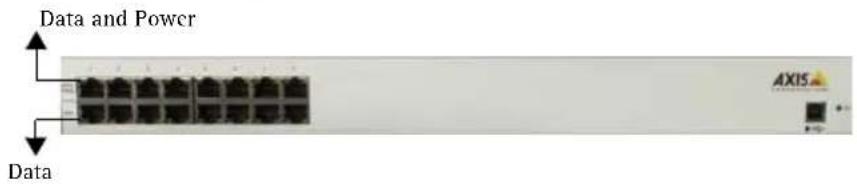
- The AXIS PoE Midspans 8P/16P consists of two rows of "Data" and "Data & Power" ports. The ports use RJ-45 data sockets. Connect only RJ-45 data cables to these sockets. Do not connect telephone cables into these ports.
- Do not work on the AXIS PoE Midspans 8P/16P system or connect or disconnect cables, when there is lightning.
-
The AC or DC plug/socket combination must be accessible at all times, as it is the main disconnect device to the product.
-
Before servicing the product, always disconnect the product from its AC source.
- Abide by appropriate National laws and regulations when it comes to discarding this product.
Power Cord Requirements
Power cords must meet the requirements for the country they are used in.
USA and Canada · The cord must have a minimum of 10A rated current competence.
The cord must be CSA or UL approved.
- The minimum requirement for the flexible cord is:
18AWG(10A)
- Three-conductor (line, neutral, ground)
- Type SV (Stranded Vacuum Rubber Jacketed) or SJ (Stranded Junior Rubber Jacketed) or SVT (Stranded Vacuum Rubber Jacketed Thermoplastic) or SJT (Stranded Junior Thermoplastic)
- The plug must be earth-grounded with a NEMA 5-15P (15A, 125 V) or NEMA 6-15P (15A, 250 V) configuration.
Europe and South America Switzerland: The supply plug must comply with SEV/ASE 1011.
Denmark: The supply plug must comply with section 107-2-D1, standard DK2-1a or DK2-5a.
United Kingdom: The Midspan is covered by General Approval (section 16.16.060), NS/G/12345/J100003, for indirect connection to a public telecommunication system
France and Peru: IT equipment cannot power this device. In the case of an IT powered device, the unit needs to be powered by 230V through an isolation transformer with a ratio of 1:1 and the secondary connection (Neutral) is properly grounded.
- The Midspan must have access to a power outlet. Disconnect the power cord from the outlet, to eliminate power from the device.
- The flexible cord that connects to the Midspan must have a configuration to connect with an EN60320/IEC320 inlet connector.
- According to the EN60950/IEC 950 specifications, this device functions under SELV (Safety Extra Low Voltage) conditions. The conditions are true if the equipment and the connected device functions under SELV conditions.
- The AXIS PoE Midspans 8P/16P meet the UL/cUL per EN60950 safety standard. This is displayed in the back side of the product.
Hardware Setup
Appearance
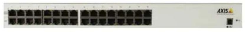
Front side of AXIS PoE 16P Midspan
AC Power Connector at the back

Data Input Ports
The AXIS PoE Midspans 8P/16P have 10Base-T/100Base-TX data input ports, that have straight-wired configuration. These ports carry Ethernet data (Tx/Rx) over the standard 2-wire pairs (pins 1/2 and 3/6).
Data and Power Output Ports
The AXIS PoE Midspans 8P/16P Data and Power ports have straight-wire configuration. They are designed to carry Ethernet data and DC power over the standard 2-wire pairs (pins 1/2 and 3/6; PoE mode A).

Installation
Connecting Power Cables
The AC power cable is connected to the AC power connector located in the rear side of the AXIS PoE Midspans 8P/16P and the power outlet.
Connecting Ethernet Cables
The ports in the product's front panel are configured as 'route through' ports for all the eight/ sixteen RJ-45 connectors. Use Category 5 cabling in making connections.
- Connect cables from the ethernet switch to the data ports - on the bottom row of the AXIS PoE Midspans 8P/16P.
- Connect the cables from the IEEE 802.3af powered devices to the corresponding Data and Power ports on the top row of the AXIS PoE Midspans 8P/16P.
Powering Up
AXIS PoE Midspans 8P/16P are powered by the power cord. In order to apply or remove power to or from the Midspan, connect or disconnect the AC power cable to or from the AC power connector on the rear side of the unit.
With AC power the unit starts-up and the internal fans are active. The device runs through a quick power-on test, which takes less than 10 seconds. During this period, all ports are initially disabled and the port indicators light up. The sequence of the port LEDs are shown in the section below - LED Indicator. Ports now operate under normal conditions.
LED Indicator
| Indicators | Conditions | ||||
| Off Green Orange | |||||
| static blinking | static blinking | ||||
| Power LED | Midspan not powered | Midspan powered | n/a n/a n/a | ||
| Data & Power | Port disabled | Port connected | Port connected; data port disconnected | Port has an error | Port is disconnected, but enabled |
Rack-Mounting Installation
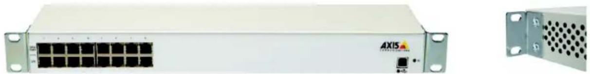
Position the Midspan on the rack. Arrange the mounting bracket to the corresponding screw holes in the Midspan. Keep the screw area visible to insert screws, and then tighten them.

Technical Specifications
| Parameters Specifications | |
| Mechanical Specifications | |
| Dimensions 17.25 inch (438 mm) length 8.98 inch (228 mm) width 1.75 inch (44.5 mm) height 9lbs (4.08 Kg) weight | |
| Environmental Specifications | |
| Temperature Operating: 32°F to 104°F (0°C to +40°C) Non-Operating: -77°F to 149°F (-25°C to +65°C) | |
| Relative Humidity Operating: 5% to 90% Non-Operating: 5% to 90% | |
| Maximum heat dissipation of the AXIS PoE Mid-spans 8P/16P | AC mode =125W |
| Electrical Specifications | |
| AC Input voltage rating 100V AC to 240VAC | |
| AC Input voltage range 90V AC to 264VAC | |
| AC Input current 5.5A (rms) at Max. load | |
| AC Input frequency 47Hz to 63H | |
| Max. In-rush current 30A for 115VAC at Max. load 60A for 230VAC at Max. load | |
| AC Output voltage 480: 50VDC 56VDC: 56VDC | |
| Max. load current 480: 0.32A 56VDC: 0.275A | |
| Output Power, per port 15.4W (not to exceed total output power) | |
| Total Output Power No. of ports: 8 - 125W max, 16 - 250W max | |
| Nominal Output Voltage | 44VDC to 57VDC |
| Approvals | • cUL/UL • TUV • CE |
Troubleshooting
If problems occur with the Midspan, please refer to the table below. The troubleshooting solutions provided can only solve minor problems. If your problem is not listed, please contact our local office for further technical assistance.
| Problem Possible Solutions | |
| Midspan does not power up 1. Ensure that AC power cord is connected. 2. Ensure that AC power cord is in good condition. 3. If neither of the above is the problem, disconnect the AC power cord and reconnect. Observe Port LEDs to verify proper power up. | |
| AC LED unlit Verify if the Midspan is properly connected to an AC power source. | |
| Data and Power Port LED do not light 'green' | Ensure Ports are connected to a Network. Verify the following: 1. Power is applied to the Midspan 2. Network Ethernet cable is connected to the Data port 3. Powered device Ethernet cable is connected to the Data &t Power port 4. The right kind of Ethernet cable is used; do not use crossover-type Ethernet cable 5. Cable pairs are connected to corresponding ports. |