
T8123 HIGH - Network card / adapter AXIS - Free user manual and instructions
Find the device manual for free T8123 HIGH AXIS in PDF.

| Product Type | 1-port Power over Ethernet (PoE) Injector |
| Brand | Axis |
| Model | T8123 High PoE |
| Input Power | 100-240 V AC, 50-60 Hz, 1.5 A max |
| Output Voltage | 52-56 V DC |
| Maximum Output Power | 30 W |
| Input Ethernet Interface | 10/100/1000Base-T, female RJ45 connector |
| Output Ethernet Interface | 10/100/1000Base-T with 55 V DC, female RJ45 connector |
| Wiring | Data on pairs 1/2 and 3/6 (10/100) or 4 pairs (Gigabit); voltage on pairs 4-5 and 7-8 |
| Recommended Cable | Category 5e or higher, shielded (FTP) recommended |
| LED Indicators | Green: camera connected; blinking: overload; off: no camera; steady green: AC power |
| Operating Temperature | -10 °C to 55 °C |
| Storage Temperature | -40 °C to 70 °C |
| Operating Humidity | 10% to 90% (non-condensing) |
| Estimated Dimensions (L x W x H) | 130 x 75 x 35 mm |
| Estimated Weight | 0.6 kg |
| Mounting | Wall mounting via rear holes, screw spacing: 9.17 cm |
| PoE Standard | IEEE 802.3af compliant, doubled power (High PoE) |
| Intended Use | Powering Axis PTZ cameras and other PoE devices |
| Included Accessories | Power cord, printed documentation, warranty document |
| Maintenance and Safety | Keep away from heat, humidity, and dust; do not block ventilation; use an approved power cord |
Frequently Asked Questions - T8123 HIGH AXIS
User questions about T8123 HIGH AXIS
0 question about this device. Answer the ones you know or ask your own.
Ask a new question about this device
Download the instructions for your Network card / adapter in PDF format for free! Find your manual T8123 HIGH - AXIS and take your electronic device back in hand. On this page are published all the documents necessary for the use of your device. T8123 HIGH by AXIS.
USER MANUAL T8123 HIGH AXIS
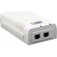
AXIS T8123 High PoE Midspan 1-port
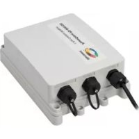
AXIS T8126 High PoE Splitter 12V
AXIS T8128 High PoE Splitter 24V

Safety information (for AXIS High PoE Midspan only)
Installation and removal of the AXIS High PoE Midspan must be carried out by qualified
personnel only.
- AC Power Cable Set:
The power cable must have regulatory agency approval for the specific country in which it is used (for example, UL, CSA, VDE).
- The power cable must be a three-conductor type (two current carrying conductors; one ground conductor) terminated on one end by an IEC 60320 appliance coupler (for connection to the AXIS High PoE Midspan), and on the other end by a plug containing a ground (earthing) contact.
- The power cable must be rated for a minimum of 250Vac RMS operation, with a minimum rated current capacity of 5 amps (or a minimum wire gauge of 18 AWG (0.75mm^2)
Note:AXIS High PoE Midspans installed in Australia require power cables with a minimum wire gauge of 16 AWG (1.0mm^2)
- The AC wall socket-outlet must be near the AXIS High PoE Midspan and easily accessible. You can remove AC power from the AXIS High PoE Midspan by disconnecting the AC power cable from either the wall socket-outlet or the AXIS High PoE Midspan appliance coupler.
- The AXIS High PoE Midspan data and data/power interfaces are qualified as SELV (Safety Extra-Low Voltage) circuits according to IEC 60950. These interfaces can only be connected to SELV interfaces on other equipment.
WARNING!
- Read the installation instructions before connecting the AXIS High PoE Midspan to its power source.
- Follow basic electricity safety measures whenever connecting the AXIS High PoE Midspan to its power source.
- A voltage mismatch can cause equipment damage and may pose a fire hazard. If the voltage indicated on the label is different from the power outlet voltage, do not connect the AXIS High PoE Midspan to this power outlet.
- This product relies on the building installation for short-circuit (over current) protection. Ensure that a fuse or circuit breaker no larger than 120 VAC, 3A. U.S. (240 VAC, 1.5A international) is used on the phase conductor.
- The AXIS High PoE Midspan "Data In" and "Data & Power Out" ports are shielded RJ-45 data sockets. They cannot be used as Plain Old Telephone Service (POTS) telephone sockets. Only RJ-45 data connectors may be connected to these sockets.
Notice:
In keeping with its policy to improve products, as new technology, components, software, and firmware become available, Axis reserves the right to change specifications without prior notice.
Technical support (for AXIS High PoE Midspan and Splitters)
Should you require technical assistance, please contact your Axis reseller. If your questions cannot be answered immediately, the reseller will forward your queries through the appropriate channels to ensure rapid response. If you are connected to the Internet, you can:
- Download user documentation
- Find answers to resolved problems in the FAQ database
Search by product, category, or phrases
Report problems to Axis support by logging in to your private support area - Visit Axis Support at www-axis.com/techsup/
Electromagnetic Compatibility (EMC)
This equipment generates, uses and can radiate radio frequency energy and, if not installed and used in accordance with the instructions, may cause harmful interference to radio communications. However, there is no guarantee that interference will not occur in a particular installation.
If this equipment does cause harmful interference to radio or television reception, which can be determined by turning the equipment off and on, the user is encouraged to try to correct the interference by one or more of the following measures: Re-orient or relocate the receiving antenna. Increase the separation between the equipment and receiver. Connect the equipment to an outlet on a different circuit to the receiver. Consult your dealer or an experienced radio/TV technician for help. Shielded (STP) network cables must be used with this unit to ensure compliance with EMC standards.
USA - This equipment has been tested and found to comply with the limits for a Class B computing device pursuant to Subpart B of Part 15 of FCC rules, which are designed to provide reasonable protection against such interference when operated in a commercial environment. Operation of this equipment in a residential area is likely to cause interference, in which case the user at his/her own expense will be required to take whatever measures may be required to correct the interference.
Canada - This Class B digital apparatus complies with Canadian ICES-003.
Europe - C E This digital equipment fulfills the requirements for radiated emission according to limit B of EN55022, and the requirements for immunity according to EN55024 residential and commercial industry.
Japan - This is a class B product based on the standard of the Voluntary Control Council for Interference from Information Technology Equipment (VCCI). If this is used near a radio or television receiver in a domestic environment, it may cause radio interference. Install and use the equipment according to the instruction manual.
Australia - This electronic device meets the requirements of the Radio communications
(Electromagnetic Compatibility) Standard AS/NZS CISPR22.
WEEE Directive
The European Union has enacted a Directive 2002/96/EC on Waste Electrical and Electronic Equipment (WEEE Directive). This directive is applicable in the European Union member states.

The WEEE marking on this product (see right) or its documentation indicates that the product must not be disposed off together with household waste. To prevent possible harm to human health and/or the environment, the product must be disposed off in an approved and environmentally safe recycling process. For further information on how to dispose off this product correctly, contact the product supplier, or the local authority responsible for waste disposal in your area.
Business users should contact the product supplier for information on how to dispose off this product correctly. This product should not be mixed with other commercial waste. For more information, visit www-axis.com/techsup/
AXIS T8123 High PoE Midspan 1-port is identical to the Microsemi PD-9001G-40 (1-port High Power over Ethernet Midspan).
AXIS T8126 High PoE Splitter 12V and AXIS T8128 High PoE Splitter 24V are identical to the Microsemi PD-AS-701/12 and PD-AS-701/24 (Power over Ethernet Active Splitter).
AXIS T8123
Package contents
| AXIS High PoE Midspan AXIS T81 | 23 High PoE Midspan 1-port |
| Power cable (region specific) Europe | UPE UK USA Japan Australia |
| Printed material Installation guide | Warranty document |
Functions and features
The AXIS T8123 High PoE Midspan 1-port injects 55V DC power into the spare pairs of the Ethernet cabling. It maintains IEEE802.3af specification parameters while doubling the output power. These power levels allowed a new range of Ethernet-based applications such as PTZ Cameras to use the High PoE Midspan.
Preliminary steps
- Ensure AC power is applied to the AXIS T8123, using an operational AC cable with appropriate ground connection.
- Ensure that output Ethernet cable is connected to the Data & Power Out port.
- Verify that a power ready Ethernet compatible device or splitter is connected.
Note:
Do not use a cross over cable between the AXIS T8123 output port and the powered device.
Installation
- Connect the AXIS T8123 to an AC outlet (100-240 VAC), using a standard power cable.
- Connect the unit Data In jack (input) to your remote Ethernet network switch using an Ethernet cable.
- Connect the Data & Power Out jack (output) to your Axis splitter or camera, using an Ethernet cable.
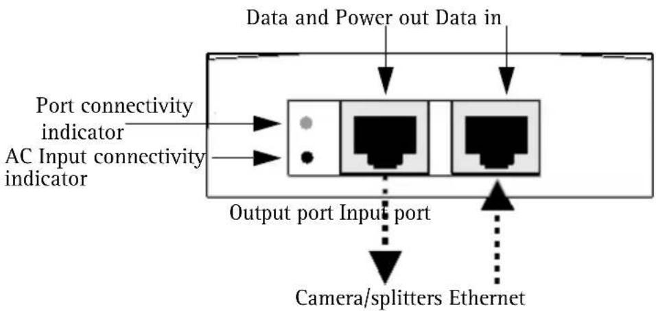
Indicators
| LED Color Indication | ||
| Port Unlit No camera connected | ||
| Green 1 Hz blinking Over current or short circuit condition on the port | ||
| AC input Steady | green AC power connected | |
Specifications
Environmental
| Mode Temperature Humidity | ||
| Operating -10 to 55°C | 14 to 131°F | 10 to 90% (no condensation allowed) |
| Storage -40 to 70°C | -24 to 158°F |
Electrical
| Input voltage 100 -240VAC (50-60 Hz) | |
| Input current 1.5A (max) | |
| Maximum Available Output Power 30W | |
| Nominal Output Voltage 55V DC |
Ethernet interface
| Input (Data In): RJ45 female socket Ethernet 10/100/1000Base-T | |
| Output (Data & Power Out): RJ45 female socket Ethernet 10/100/1000Base-T, plus 55 VDC | |
| Wiring Data provided over pairs 1/2 and 3/6 for 10/100 Ethernet, over all four pairs for Gigabit Ethernet Power provided over spare pairs 4/5(+) and 7/8(-). | |
| Network cable Category 5 (or higher), foiled twisted-pair (FTP) cable recommended. |
Troubleshooting
| Symptom Corrective steps | |
| Midspan does not power up 1. Verify | that an approved power cable is used. 2. Verify that the voltage at the power inlet is between 100 and 240V AC. 3. Remove and re-apply power to the device and check the indicators during power up sequence. |
| A port indicator is not lit and the PD (powered device) does not operate | 1. The Midspan did not detect a PD; and the port is not enabled. 2. Verify that the PD is designed for PoE operation. 3. Verify that you are using a standard Category 5/5e/6, straight-wired cable, with four pairs. 4. If there is an external PoE device is connected, replace it to verify that it is functioning properly. 5. Ensure that the input Ethernet cable is connected to the Data In port. 6. Verify that the PD is connected to the Data & Power port. 7. Try to reconnect the same PD into a different Midspan. If it works, there is probably a faulty port or RJ-45 connection. 8. Verify that there is no shortcut over any of the twisted pair cables or over the RJ45 connectors. |
| The end device operates, but there is no data link | 1. Verify that the port indicator on the front panel is continuously lit. 2. If an external PoE device is in use, replace it with a known good PoE device. 3. Verify that for this link, you are using standard UTP/FTP Category 5 straight (non-crossover) cabling, with all four pairs. 4. Verify that the Ethernet cable length is less than 100 meters (333 feet) from the Ethernet source to the powered device. 5. Try to reconnect the same PD into a different Midspan. If it works, there is probably a faulty port or RJ-45 connection. |
Mounting instructions
The AXIS T8123 may be wall or bench mounted using the rear side holes.
Note the following before mounting the AXIS T8123 to a fixed location:
- Do not cover the midspan or block the airflow to the product with any foreign object. Keep the midspan away from excessive heat and humidity, and free from vibration and dust.
- Ensure that the cable length from the Ethernet network source to your Axis video product does not exceed 100 meters (333 feet). The midspan is not a repeater and does not amplify the Ethernet data signal.
- Use a splitter if desired, but ensure that the splitter is connected close to your Axis video product and not to the Midspan.
- There is no "on-off" switch; simply plug the AXIS T8123 into an AC power outlet.
To mount:
- Install two screws vertically at a distance of 9.17cm (3.61") on the wall or shelf.
- Align the AXIS T8123 mounting slots to capture the surface screws.
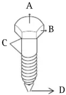
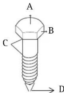
A 5.8 to 7.0 ~mm (0.23" to 0.27" )
B 2.0mm (0.08")
C 1.5mm to 2.5 mm (0.059" to 0.098")
D 3.0 mm (0.12")
AXIS T8126 High PoE Splitter 12V and AXIS T8128 High PoE Splitter 24V
Package contents
| AXIS High PoE Splitter AXIS T8 | 126 High PoE Splitter 12V AXIS T8128 High PoE Splitter 24V |
| Power adapter cable AXIS T8126 | 126 High PoE Splitter 12V: ·1 x cable for AXIS 213 PTZ, AXIS 214 PTZ, AXIS 215 PTZ ·1 x cable for AXIS 225FD ·1 x cable for AXIS cameras with PS-K connector ·length for each cable - 1m / 3.33 feet AXIS T8128 High PoE Splitter 24V: ·1 x cable for AXIS 231D+, AXIS 232D+, AXIS 233D ·length: 5m / 16.65 feet |
| Printed material Installation guide | |
Installation
- Place the High PoE splitter as close as possible to the Axis video product.
- Connect the Ethernet cable from the Data Out port to the Ethernet input of the Axis video product.
- Connect the power adapter cable to the DC Out port of the splitter to the power input of your Axis video product.
Note:
For AXIS 225FD, AXIS 231D + / AXIS 232D+ , and AXIS 233D, follow the Installation Guide of the product (also available at www-axis.com/techsup)
- Connect the Ethernet cable from the AXIS T8123 High PoE Midspan to the PoE In port of the splitter.
- Verify that PWR IN LED turns green.
- Verify that PWR Out LED turns green and that your Axis network camera is powered up.
Specifications
Environmental
| Mode Temperature Humidity | ||
| Operating 0 - 40°C | 32 to 104°F | 10 to 90% (no condensation allowed) |
| Storage -20 to 70°C | -4 to 158°F |
Electrical
| Input voltage 44-57 VDC | |
| Output voltage 12 VDC for | AXIS T8126 24 VDC for AXIS T8128 |
| Output current 2 A max for | AXIS T8126 1 A max for AXIS T8128 |
| Output power 24 W max | |
| Output connector | DC barrel connector 6.4x2.5 mm (0.252x0.098"); with "+" centered |
Ethernet interface
| Input (Data In): RJ45 female socket, with DC voltage | on wire pairs 7/8 and 4/5. Ethernet 10/100/1000Base-T, plus 48 VDC |
| Output (Data &t Power Out): RJ45 female socket | Ethernet 10/100/1000Base-T |
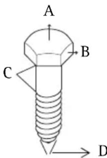
AXIS T8123
| A 5.8 | to 7.0 mm (0.23" to 0.27") |
| B 2.0 | mm (0.08") |
| C 1.5 | mm to 2.5 mm (0.059" to 0.098") |
| D 3.0 | mm (0.12") |
| A 5.8 | a 7.0 mm (0.23" to 0.27") |
| B 2.0 | mm (0.08") |
| C 1.5 | mm a 2.5 mm (0.059" a 0.098") |
| D 3.0 | mm (0.12") |
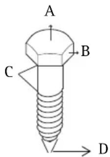
AXIS T8126 High PoE Splitter 12V e AXIS T8128 High PoE Splitter 24V
| A 5.8 | to 7.0 mm (0.23" to 0.27") |
| B 2.0 | mm (0.08") |
| C 1.5 | mm to 2.5 mm (0.059" a 0.098") |
| D 3.0 | mm (0.12") |
AXIS T8126 High PoE Splitter 12V e AXIS T8128 High PoE Splitter 24V

- Safety information (for AXIS High PoE Midspan only)
- WARNING!
- Notice:
- Technical support (for AXIS High PoE Midspan and Splitters)
- Electromagnetic Compatibility (EMC)
- WEEE Directive
- AXIS T8123
- Package contents
- Functions and features
- Preliminary steps
- Note:
- Installation
- Indicators
- Specifications
- Environmental
- Electrical
- Ethernet interface
- Troubleshooting
- Mounting instructions
- To mount:
- AXIS T8126 High PoE Splitter 12V and AXIS T8128 High PoE Splitter 24V
- AXIS T8126 High PoE Splitter 12V e AXIS T8128 High PoE Splitter 24V
Brand : AXIS
Model : T8123 HIGH
Category : Network card / adapter