
FishEasy 350C Portable - Fish finder EAGLE - Free user manual and instructions
Find the device manual for free FishEasy 350C Portable EAGLE in PDF.
| Product type | Portable fish finder |
| Brand and model | Eagle FishEasy 350C Portable |
| Dimensions (L x W x H) | 10.8 x 6.6 x 14.7 cm |
| Weight (with batteries) | Approximately 0.5 kg |
| Power supply | 10-17 V DC; 8 AA batteries in portable mode |
| Power consumption | 200 mA (backlight off) / 250 mA (on) |
| Sonar frequency | 200 kHz |
| Transmit power | 800 W peak-to-peak; 100 W RMS |
| Maximum depth | 182 m (600 ft) |
| Display | 3.5-inch (8.9 cm) color TFT screen; 320 x 240 pixels |
| Included transducer | Skimmer HST-WSU (transom, motor, hull, or portable mount) |
| Temperature sensor | Built into transducer (surface temperature) |
| Optional speed sensor | Yes, for speed and distance |
| Alarms | Shallow water, deep water, fish (audible) |
| Main functions | ASP, ColorLine, Fish I.D., FasTrack, 2X/4X Zoom, depth cursor, simulator |
| Available languages | 10 languages (French, English, German, etc.) |
| Maintenance and cleaning | Clean the transducer with soap and water; avoid extreme temperatures |
| Warranty | 1 year (Navico Limited) |
| Repairability and spare parts | Parts available via customer service; repair by a professional possible |
Frequently Asked Questions - FishEasy 350C Portable EAGLE
User questions about FishEasy 350C Portable EAGLE
0 question about this device. Answer the ones you know or ask your own.
Ask a new question about this device
Download the instructions for your Fish finder in PDF format for free! Find your manual FishEasy 350C Portable - EAGLE and take your electronic device back in hand. On this page are published all the documents necessary for the use of your device. FishEasy 350C Portable by EAGLE.
USER MANUAL FishEasy 350C Portable EAGLE
Installation & Operation Instructions
Copyright © 2008 Navico All rights reserved.
Eagle® is a registered trademark of Navico. FishEasy® 350C is a registered trademark of Navico.
Navico may find it necessary to change or end our policies, regulations, and special offers at any time. We reserve the right to do so without notice. All features and specifications subject to change without notice. All screens in this manual are simulated.
No part of this manual may be copied, reproduced, republished, transmitted or distributed for any purpose, without prior written consent of Navico. Any unauthorized commercial distribution of this manual is strictly prohibited.
For free owner's manuals and the most current information on this product, its operation and accessories, visit our web site: www.eaglesonar.com
Eagle Electronics P.O.Box 669 Catoosa,OK USA 74015 Printed in USA.
Table of Contents
Capabilities and Specifications: FishEasy 350C. 3
How to use this manual: typographical conventions 4
Installation & Accessories. 5
Preparations 5
Transducer Installation 5
Selecting a Transducer Location 6
How low should you go? 8
Transom Transducer Assembly And Mounting 8
Trolling Motor Bracket Installation (single-frequency only) 14
Transducer Orientation and Fish Arches 15
Speed/Temperature Sensors 17
Speed Sensor Installation 20
Power Connections 22
Bracket Installation 24
Portable Sonar Installation 27
Installing the Batteries 27
Portable Transducer Assembly 28
Basic Sonar Operation 31
Keyboard Basics 31
Memory 32
32
Pages 35
Basic Sonar Quick Reference 38
Sensitivity 39
Advanced Sonar Options & Other Features 43
ASPTM (Advanced Signal Processing) 43
Alarms. 44
Backlight Level. 46
Calibrate Speed 46
Chart Speed 47
ColorLineTM 47
Contrast 48
Depth Cursor 49
Depth Range - Automatic 50
Depth Range - Manual. 50
FasTrackTM 51
Fish I.D. TM 51
FishTrackTM 52
Overlay Data 53
Ping Speed & HyperScrollTM 54
Pop-up Help 56
Reset Options. 56
Reset Water Distance. 56
Set Keel Offset. 57
Set Language. 58
Software Version Information 58
SonarChartMode. 58
Sonar Simulator 58
StopChart. 59
Surface Clarity 59
Transparency 60
Units of Measure 61
Zoom Pan 62
Index 63
NOTICE!
The storage and operation temperature for your unit is from -4 degrees to +167 degrees Fahrenheit (-20 degrees to +75 degrees Celsius). Extended storage in temperatures higher or lower than specified will damage the liquid crystal display in your unit. This type of damage is not covered by the warranty. For more information, contact the factory's Customer Service Department; phone numbers are inside the manual's back cover.
Capabilities and Specifications: FishEasy 350C General
Case size: 5.8" H x 4.3" W x 2.5" D (14.7 cm H x 10.8 cm W x 6.6 cm D) sealed, waterproof; suitable for saltwater use.
Display: 1/4 VGA color, transflective TFT display; 3.5" (8.9 cm) diagonal viewing area.
Resolution: 320 pixels (vert.) x 240 pixel (horiz.) resolution; 153,600 total pixels
Backlighting: Backlit screen and keypad for night use.
Input power: 10 to 17 volts DC.
Current drain: 200 ma lights off; 250 ma lights on.
Back-up memory:......Built-in memory stores sonar settings when unit is turned off.
Sonar
Frequency: 200 kHz.
Transducers: A model HST-WSU Skimmer transducer comes packed with your sonar unit. Operates at speeds up to 70 mph (61 kts).
Transmitter: 800 watts peak-to-peak power (typical); 100 watts RMS power (typical).
Sonar sounding
depth capability: 600 feet (182 meters). Actual capability depends on transducer configuration and installation, bottom composition and water conditions. All sonar units typically read deeper in fresh water than in salt water.
Depth display: ......... Continuous digital readout.
Audible alarms:............Deep/shallow/fish.
Automatic ranging: ....Yes, with instant screen updates.
Zoom bottom track:......Yes.
Split-screen zoom: .......Yes.
Surface water temp: ....Yes, built into transducer. Optional additional temp sensors for live well, bait well, etc. are available.
Speed/distance log: ....Yes, with optional speed sensor.
How to use this manual: typographical conventions Arrow Keys
Arrow keys are represented by symbols like these ( ) , which denote the up and down arrow keys.
Keyboard
When the text refers to a key to press, the key is shown as ENT (Enter/Pages) and MENU (Menu/Power).
Menu Commands
When you are prompted to select a menu option, it will be shown in small capital letters, in a bold sans serif type like: DEPTH CURSOR.
Instructions = Menu Sequences
For example, instructions for turning on the Fish ID™ feature would look like this:
- Press MENU | ↓↑ to SONAR FEATURES | ENT.
- Press to FISH ID SYMBOLS | ENT | EXIT | EXIT.
Step 1: "Press the Menu key then use arrow keys to select (highlight) the Sonar Features menu command. Then press the Enter key."
Step 2 would mean: "Use the arrow keys to select (highlight) the Fish ID symbols. Press the Enter key, then press the Exit key twice."
Installation & Accessories
Preparations
You can install the sonar in some other order if you prefer, but we recommend this installation sequence:
Caution:
You should read over this entire installation section before drilling any holes in your vehicle or vessel!
- Determine the approximate location for the sonar/GPS unit, so you can plan how and where to route the cables for the transducer and power. This will help you make sure you have enough cable length for the desired configuration.
- Determine the approximate location for the transducer and its cable route.
- Determine the location of your battery or other power connection, along with the power cable route.
- Install the transducer and route the transducer cable to the sonar/GPS unit.
- Install the power cable and route it to the sonar/GPS unit.
- Mount the sonar/GPS unit to the bracket.
Transducer Installation
These instructions will help you install your Skimmer® transducer on a transom, on a trolling motor or inside a hull. These instructions cover both single- and dual-frequency Skimmer transducers. Please read all instructions before proceeding with any installation.
The smaller single-frequency Skimmers typically use a one-piece, stainless steel mounting bracket. The larger dual-frequency Skimmers typically use a two-piece, plastic mounting bracket. The trolling motor mount uses a one-piece plastic bracket with an adjustable strap.
These are all "kick-up" mounting brackets. They help prevent damage if the transducer strikes an object while the boat is moving. If the transducer does "kick-up," the bracket can easily be pushed back into place without tools.
Read these instructions carefully before attempting the installation. Determine which of the mounting positions is right for your boat. Remember, the transducer installation is the most critical part of a sonar installation.
NOTE:
The following installation types also call for these recommended tools and required supplies that you must provide (supplies listed here are not included):
Single-frequency transom installations
Tools include: two adjustable wrenches, drill, #29 (0.136") drill bit, Phillips head screwdriver. Supplies: high quality, marine grade above-or below-waterline sealant/adhesive compound.
Dual-frequency transom installations
Tools: two adjustable wrenches, drill, #20 (0.161") drill bit, Phillips head screwdriver. Supplies: four, 1" long, #12 stainless steel slotted wood screws, high quality, marine grade above- or below-waterline sealant/adhesive compound.
Single-frequency trolling motor installations
Tools: two adjustable wrenches, Phillips head screwdriver. Supplies: plastic cable ties.
Selecting a Transducer Location
-
The location must be in the water at all times, at all operating speeds.
-
The transducer must be placed in a location that has a smooth flow of water at all times. If the transducer is not placed in a smooth flow of water, interference caused by bubbles and turbulence will show on the sonar's display in the form of random lines or dots whenever the boat is moving.
NOTE:
Some aluminum boats with strakes or ribs on the outside of the hull create large amounts of turbulence at high speed. These boats typically have large outboard motors capable of propelling the boat at speeds faster than 35mph . Typically, a good transom location on aluminum boats is between the ribs closest to the engine.
- The transducer should be installed with its face pointing straight down, if possible.
- If the transducer is mounted on the transom, make sure it doesn't interfere with the trailer or hauling of the boat. Also, don't mount it closer than approximately one foot from the engine's lower unit. This will prevent cavitation (bubble) interference with propeller operation.
- If possible, route the transducer cable away from other wiring on the boat. Electrical noise from engine wiring, bilge pumps and aerators can be displayed on the sonar's screen. Use caution when routing the transducer cable around these wires.
CAUTION: Clamp the transducer cable to transom near the transducer. This will help prevent the transducer from entering the boat if it is knocked off at high speed.
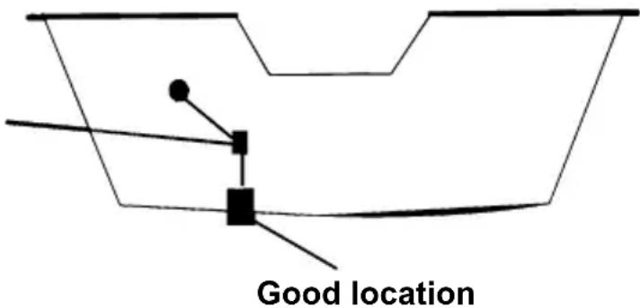
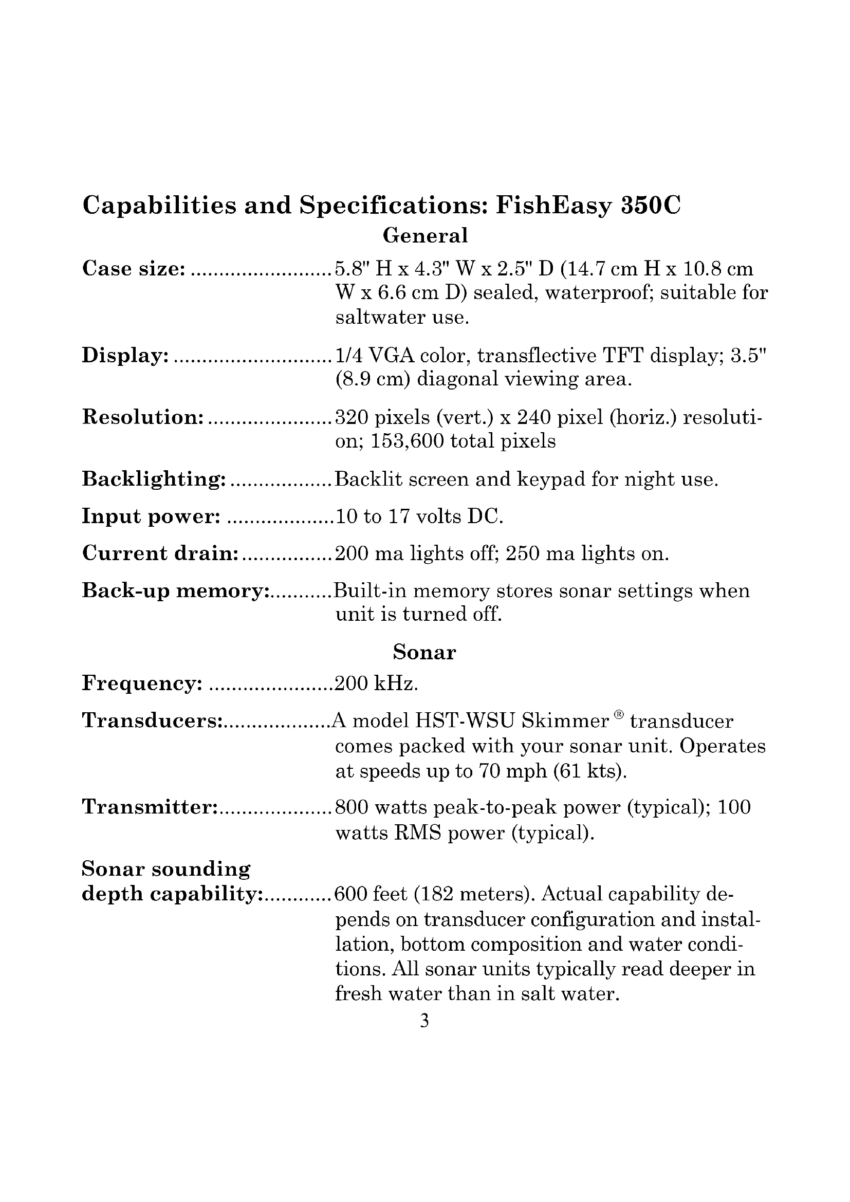
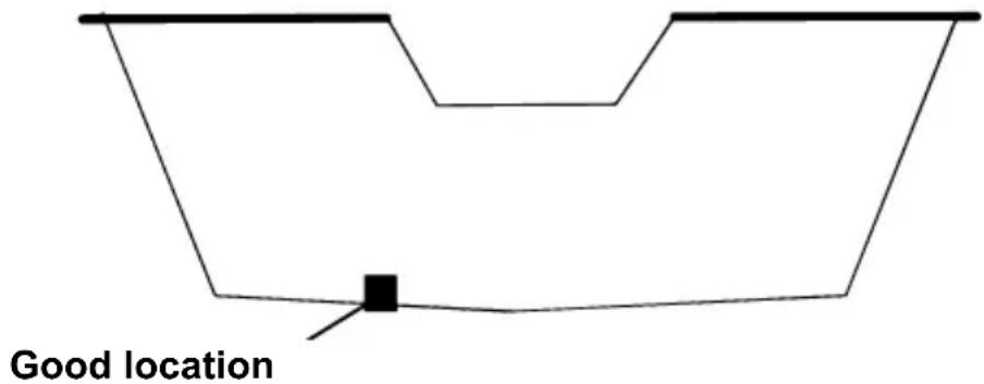
Good and poor transducer locations.
How low should you go?
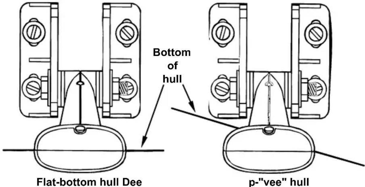
For most situations, you should install your Skimmer transducer so that its centerline is level with the bottom of the boat hull.
This will usually give you the best combination of smooth water flow and protection from bangs and bumps.

Align transducer centerline with hull bottom.
However, there are times when you may need to adjust the transducer slightly higher or lower. (The slots in the mounting brackets allow you to loosen the screws and slide the transducer up or down.) If you frequently lose bottom signal lock while running at high speed, the transducer may be coming out of the water as you cross waves or wakes. Move the transducer a little lower to help prevent this.
If you cruise or fish around lots of structure and cover, your transducer may be frequently kicking up from object strikes. If you wish, you may move the transducer a little higher for more protection.
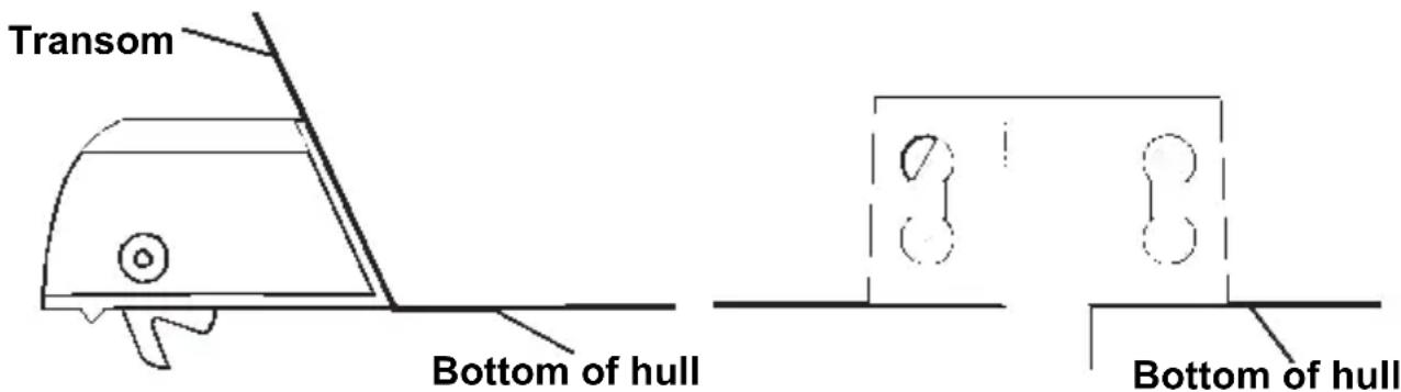
There are two extremes you should avoid. Never let the edge of the mounting bracket extend below the bottom of the hull. Never let the bottom – the face – of the transducer rise above the bottom of the hull.
Transom Transducer Assembly And Mounting
The best way to install these transducers is to loosely assemble all of the parts first, place the transducer's bracket against the transom and see if you can move the transducer so that it's parallel with the ground.
The following instructions sometimes vary depending on the mounting bracket that came with your transducer. Single-frequency Skimmers come with a one-piece stainless steel bracket, while dual-frequency Skimmers come with a two-piece plastic mounting bracket. Use the set of instructions that fits your model.
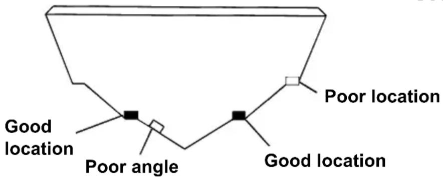
1. Assembling the bracket.
A. One-piece bracket: Press the two small plastic ratchets into the sides of the metal bracket as shown in the following illustration. Notice there are letters molded into each ratchet. Place each ratchet into the bracket with the letter "A" aligned with the dot stamped into the metal bracket. This position sets the transducer's coarse angle adjustment for a 14irc transom. Most outboard and stern-drive transoms have a 14irc angle.
B. Two-piece bracket: Locate the four plastic ratchets in the transducer's hardware package. Press two ratchets into the sides of the plastic bracket and two on either side of the transducer as shown in the following illustrations. Notice there are letters molded into each ratchet.
Place the ratchets into the bracket with the letter "A" aligned with the alignment mark molded into the bracket. Place the ratchets onto the transducer with the letter "A" aligned with the 12 o'clock position on the transducer stem. These positions set the transducer's coarse angle adjustment for a 14irc transom. Most outboard and stern-drive transoms have a 14irc angle.

Add ratchets to bracket and transducer.
2. Aligning the transducer on the transom.
To align the transducer to the transom, side the transducer between the ratchets. Look at the transducer from the side and adjust it so that its face is parallel to the ground. The alignment letters on either side of the bracket need be the same.
If the transducer's face isn't parallel with the ground, remove the transducer and ratchets from the bracket. Place the ratchets into the holes in the bracket with the letter "B" aligned with the dot stamped in the bracket.
Reassemble the transducer and bracket and place them against the transom. Again, check to see if you can move the transducer so it's parallel with the ground. If you can, then go to step 3A.
3. Assembling the transducer.
A. One-piece bracket: Once you determine the correct position for the ratchets, assemble the transducer as shown in the following figure. Don't tighten the lock nut at this time.
Position transducer mount on transom and mark mounting holes. Side view shown (left) and seen from above (right).

Assemble transducer and bracket.
B. Two-piece bracket: Once you determine the correct position for the ratchets, assemble the transducer as shown in the figure in step 2B. Don't tighten the lock nut at this time.

Assemble transducer and bracket.
4. Drilling mounting holes.
Hold the transducer and bracket assembly against the transom. The transducer should be roughly parallel to the ground. The transducer's centerline should be in line with the bottom of the hull. Don't let the bracket extend below the hull!
Mark the center of each slot for the mounting screw pilot holes. You will drill one hole in the center of each slot.
Drill the holes. For the one-piece bracket, use the #29 bit (for the #10 screws). For the two-piece bracket, use the #20 bit (for the #12 screws).
5. Attaching transducer to transom.
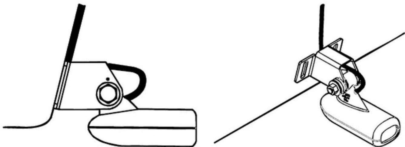
Both bracket types: Attach the transducer to the transom. Slide the transducer up or down until it's aligned properly with the bottom of the hull as shown in the preceding and following figures. Tighten the bracket's mounting screws, sealing them with the sealant.
Adjust the transducer so that it's parallel to the ground even if you have a Deep-"vee" hull. Tighten the nut until it touches the outer washer, then add 1/4 turn. Don't over tighten the lock nut! If you do, the transducer won't "kick-up" if it strikes an object in the water.
Align transducer centerline with hull bottom and attach transducer to transom. Rear view of dual-frequency Skimmer shown.
- Route the transducer cable through or over the transom to the sonar unit. Make sure to leave some slack in the cable at the transducer.
If possible, route the transducer cable away from other wiring on the boat. Use caution when routing the transducer cable around these wires.
WARNING:
Clamp the transducer cable to the transom close to the transducer. This can prevent the transducer from entering the boat if it is knocked off at high speed.
Caution:
If you need to drill a hole in the transom to pass the connector through, the required hole size be 1 . If you drill the hole, make sure it is located above the waterline. After installation, be sure to seal the hole with the same marine grade above- or below-waterline sealant used for the mounting screws.
- Make a test run to determine the results. If the bottom is lost at high speed, or if noise appears on the display, try sliding the transducer bracket down. This puts the transducer deeper into the water, hopefully below the turbulence causing the noise. Don't allow the transducer bracket to go below the bottom of the hull!
Trolling Motor Bracket Installation (single-frequency only)
-
Attach the optional TMB-S bracket to the transducer as shown in the following figure, using the hardware supplied with the transducer. (Note: The internal tooth washer is supplied with the TMB-S.)
-
Slide the adjustable strap supplied with the TMB-S through the slot in the transducer bracket and wrap it around the trolling motor. Position the transducer to aim straight down when the motor is in the water. Tighten the strap securely.

Attach motor mounting bracket to transducer.
- Route the transducer cable alongside the trolling motor shaft. Use plastic ties (not included) to attach the transducer cable to the trolling motor shaft. Make sure there is enough slack in the cable for the motor to turn freely. Route the cable to the sonar unit and the transducer is ready for use.
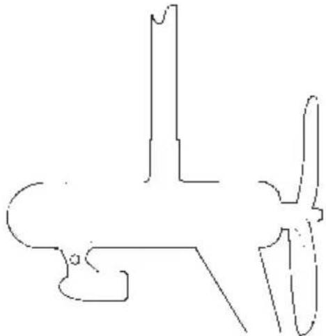
Transducer mounted on trolling motor, side view.
Transducer Orientation and Fish Arches
If you do not get good fish arches on your display, it could be because the transducer is not parallel with the ground when the boat is at rest in the water or at slow trolling speeds.
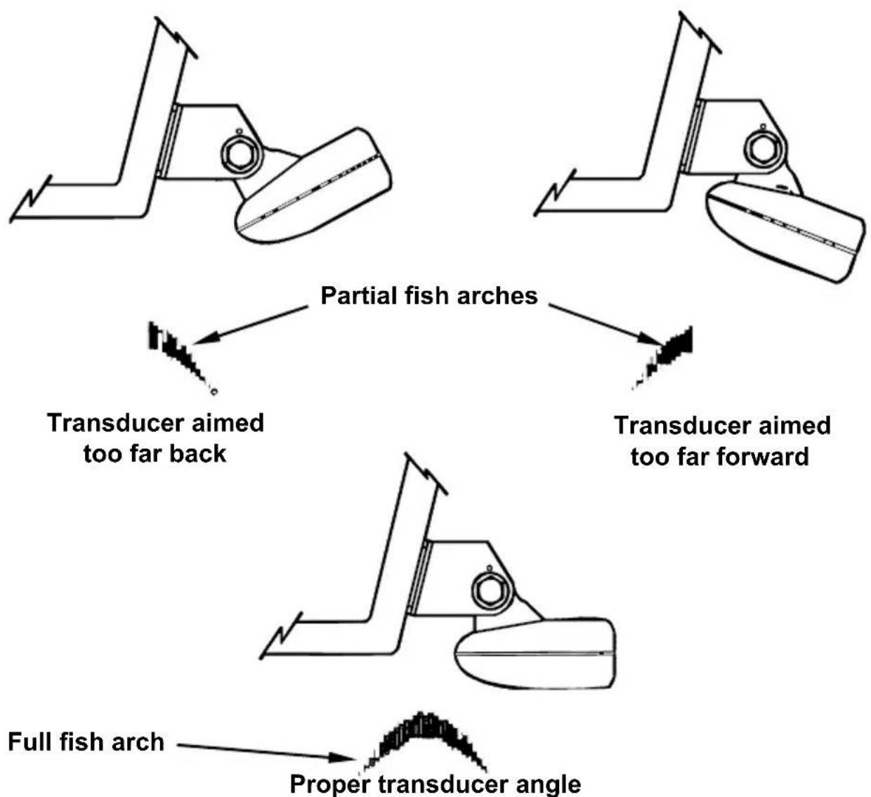
Transducer angles and their effects on fish arches.
If the arch slopes up – but not back down – then the front of the transducer is too high and needs to be lowered. If only the back half of the arch is printed, then the nose of the transducer is angled too far down and needs to be raised.
NOTE:
Periodically wash the transducer's face with soap and water to remove any oil film. Oil and dirt on the face will reduce the sensitivity or may even prevent operation.
Speed/Temperature Sensors
The FishEasy 350C can use two temperature sensors at the same time. It also can use a speed sensor, but not at the same time as you are using a secondary temp sensor. To use a speed sensor and a secondary temperature sensor at the same time, you will need a combination device.
NOTE:
If a second temp sensor is used, it must be the model TS-2U.

Full Chart page showing dual temperature display.
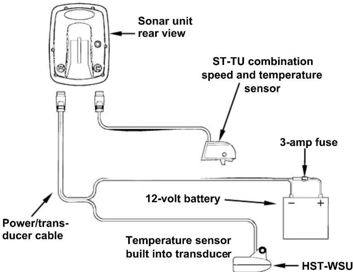
Sonar unit with external combination speed and temperature sensor. Primary temp sensor is built into the transducer.
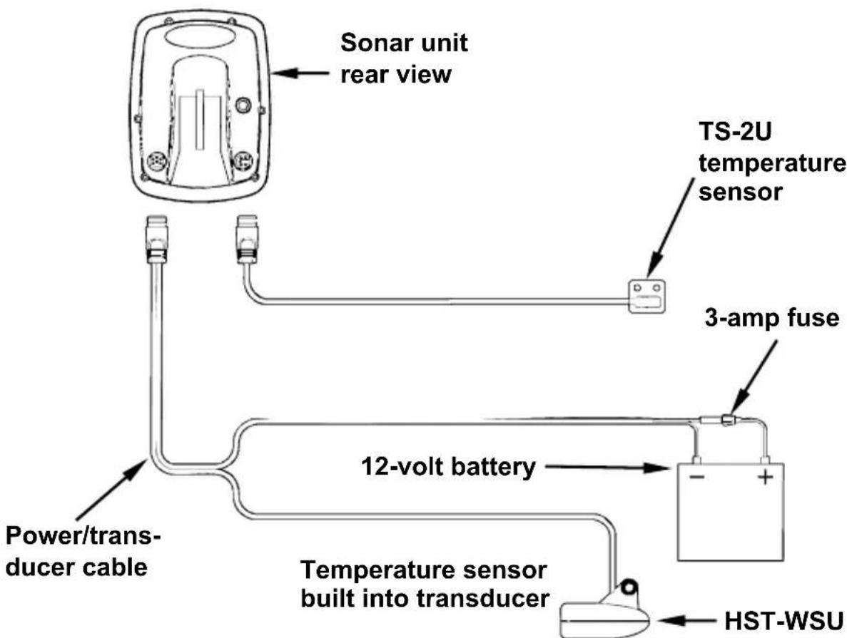
Sonar unit with secondary external temperature sensor. Primary temp sensor is built into the transducer.

Sonar unit with external speed sensor. The temperature sensor is built into the transducer.
Speed Sensor Installation
The following instructions describe how to install the speed sensor.
Recommended tools include: drill, 5/8" drill bit, 1/8" drill bit for pilot holes, screwdriver.
Required supplies include: four #8 stainless steel wood screws (3/4" long), high quality, marine grade above- or below-waterline caulking compound. (If you intend to route the sensor cable through the same hole as the transducer cable, you will need a 1" (25.4 mm) drill bit instead of the 5/8" drill bit.)
To install speed sensor:
- Find a location on the boat's transom where the water flow is smoothest. Don't mount the sensor behind strakes or ribs. These will disturb the
water flow to the speed sensor. Make sure the sensor will remain in the water when the boat is on plane. Also make sure the location doesn't interfere with the boat's trailer. Typically, the sensor is mounted about one foot to the side of the transom's centerline.
- Place the sensor on the transom. The bottom of the bracket should be flush with the hull's bottom. Using the sensor as a template, mark the hull for the screws' pilot holes. Drill four 1/8" holes, one in each end of the slots.
- Mount the sensor to the hull using #8 stainless steel wood screws (not included). Use a high quality, marine grade above- or below-waterline caulking compound to seal the screws. Make sure the sensor is flush with the bottom of the hull and tighten the screws.
Stern view showing good location for mounting sensor on transom.
Speed sensor mounting configuration: side view (left) and rear view (right).
- If the base of the transom has a radius, fill the gap between the transom and the sensor with the caulking compound. This will help ensure a smooth water flow.
- Route the sensor's cable through or over the transom to the sonar unit. If you need to drill a hole in the transom to pass the connector through, the required hole size is 5/8" . (The hole is 1" ( 25.4 mm ) if you intend to route the sensor cable through the same hole as the transducer cable.)
Caution:
If you drill a hole in the transom for the cable, make sure it is located above the waterline. After installation, be sure to seal the hole with the same marine grade above- or below-waterline sealant used for the screws.
The sensor is now ready for use. Connect the sensor to the accessory socket on the back of the unit. If you have any questions concerning the installation of the sensor contact your local boat dealer.
Power Connections
The unit works from a 12-volt battery system. You can attach the power cable to your boat's accessory or power buss or directly to the battery. If you use an accessory buss but have problems with electrical interference, attach the power cable directly to the battery. If the cable is not long enough, splice #18 gauge wire onto it.
CAUTION:
When using the unit in a saltwater environment, we strongly recommend that you shut off the power supply to the power cable when the unit is not in use. When the unit is turned off but still connected to a power supply, electrolysis can occur in the power cable plug. This may result in corrosion of the plug body along with the electrical contacts in the cable and the unit's power socket.
In saltwater environments we recommend you connect the power cable to the auxiliary power switch included in most boat designs.
If that results in electrical interference, or if such a switch is not available, we recommend connecting direct to the battery and installing an inline switch. This will let you shut off power to the power cable when the unit is not in use. When you are not using the unit, you should always shut off power to the power cable, especially when the power cable is disconnected from the unit.
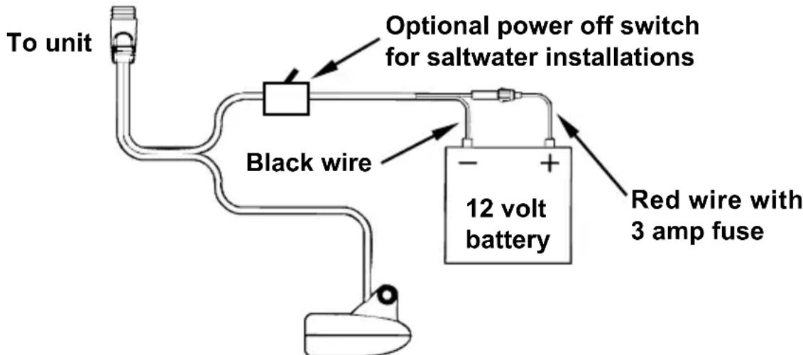
Power and transducer connections for the FishEasy 350C sonar unit (direct battery connection shown).
If possible, keep the power cable away from other boat wiring, especially the engine's wires. This will provide the best isolation from electrical noise. The power cable has two wires, red and black. Red is the positive lead, black is negative or ground. Make sure to attach the inline fuse holder to the red lead as close to the power source as possible.
CAUTION:
Do not use this product without a 3-amp fuse wired into the power cable! Failure to use a 3-amp fuse will void your warranty. For corrosion protection in saltwater or high humidity environments, apply a thin layer of electrical-grade grease to each end of the fuse before installing it in the fuse holder.
Bracket Installation
Recommended tools include: drill, 1'' (25.4 mm) drill bit, screwdriver.
Required supplies include: high quality, marine grade above- or below-waterline caulking compound, three #10 stainless steel screws. Screw length and type should be suitable for the material on which you intend to mount the bracket.
Installing the bracket:
- Mount the unit in any convenient location. Make sure there is enough clearance for it to be tilted at angles. You should also make sure there is enough room behind the unit to attach the power/transducer cable.
NOTE:
Holes in the bracket's base allow wood screw or through-bolt mounting. You may need to place a piece of plywood on the back side of thin panels to reinforce the panel and secure the mounting hardware.
-
Drill a 1" (25.4 mm) hole in the dash for the power/transducer and accessory cables. The best location for this hole is directly under the gimbal bracket location.
-
Pass the connectors up through the hole from under the dash. You can fill in the space around the cable with a marine caulking compound or purchase a cable hole cover from a marine dealer.
Using the Quick Release Mounting Bracket
These units use a quick release mounting bracket. When you run the cables through the bracket's cable slots, make sure you allow enough slack for tilting the unit and attaching the connector.
- Align the bracket over the cable hole with the cable slots facing away from you and fit the cable through one of the slots. Fasten the bracket to the dash using the three screw holes.

Front view (left) and side view (right) showing dimensions of the FishEasy 350C when mounted on quick release bracket.
- Connect the unit to power/transducer and accessory cables.
- Hold the sonar unit vertically and slide it onto the bracket from above. As you push down, the unit will lock into place with a distinct click.

FishEasy 350C quick release mounting bracket. Slots in the base allow routing the cable from beneath the mount.
- To adjust the viewing angle, pinch the ratchets with one hand, then tilt the unit with your other hand. Release the ratchets and the unit locks into the new position. To dismount the unit for storage, press the ratchets and lift the unit off the bracket.
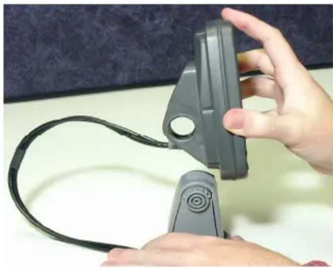

Slide the unit onto the bracket (left). To adjust the viewing angle press and release the spring-loaded ratchets while you move the unit with the other hand (right).
Portable Sonar Installation
Like many Eagle products, the FishEasy 350C sonar is capable of portable operation. It uses the optional PPP-12 portable power pack.
The power pack and portable transducers expand the uses for your sonar. The PPP-12 package includes the power pack, battery adapter and a portable transducer. The transducer can be stored inside the power pack. The PPP-12 requires eight AA alkaline batteries. Batteries are not included.
To use a portable power pack, install the batteries and then attach the sonar unit to the power pack's bracket. Plug in the power/transducer cable to complete the installation. The PPP-12 has a quick-release mounting bracket built into the case.
Installing the Batteries
Release the latch on the front of the power pack case. Open the compartment and install eight AA batteries into the adapter.
After installing the batteries, close the case and plug the sonar unit's power cable into the socket on the power pack case.

PPP-12 Portable Power Pack with FishEasy 350C stowed for transport.
Caution:
In cold weather the efficiency of dry cell batteries drops with the temperature. It is a good idea to make sure the batteries are warm before leaving home.
If the batteries do lose charge, sometimes they can be restored by placing them in a warm room or car interior.
WARNING:
Never heat the batteries over an open flame or direct hot air onto them. A fire or explosion could result.
Portable Transducer Assembly
Recommended tools for installation include a slotted screw driver and two adjustable wrenches.
- Assemble the transducer and bracket as shown in the following figure. Attach the transducer to the bracket with the supplied hardware.
- Make sure there is one washer on each side of the transducer, inside the bracket. Slide the other washer over the end of the bolt and thread the nut onto it.
- Screw the suction cup onto the bracket using the supplied screw and flat washer. Tie the nylon cord through the hole in the top of the bracket. When using this transducer, tie the other end of the nylon cord to the boat. This will help prevent the loss of the transducer if it comes off the boat.
- Clean the chosen area of the hull before attaching the suction cup. Locate the transducer on the hull as shown in the following figure. Don't allow the bracket to extend below the hull, because water pressure against it can cause the suction cup to come off at speed.
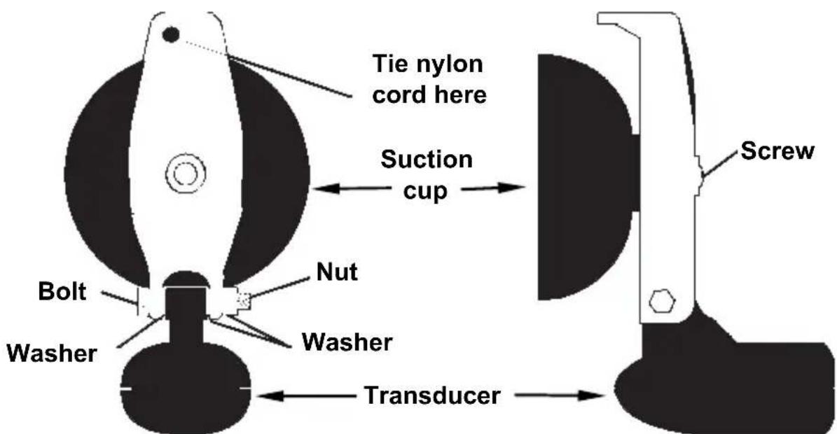
Portable transducer assembly: rear view (left) and side view (right).
- Moisten the cup and press it onto the hull as firmly as possible. Tie the nylon cord to the boat and route the transducer cable to the sonar unit. Your portable sonar is now ready for use.
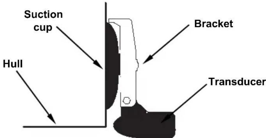
Portable transducer installed on boat transom.
NOTE:
For optimum operation, the portable transducer should be adjusted so it is parallel to the ground.
Notes
Basic Sonar Operation
Keyboard Basics
FishEasy 350c.
MENU/PWR
The MENU/PWR key is used to access menus and turn the unit on and off.
NOTE:
You must hold the MENU key down for a countdown of five in order to turn the unit off.
C
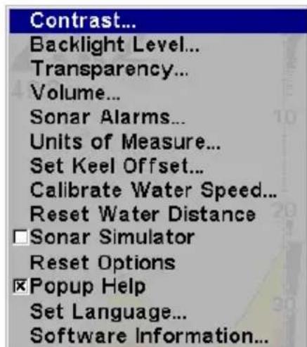
Main Menu.
- Screen (CONTRAST, BACKLIGHT LEVEL and TRANSPARENCY): adjusts the appearance the screen.
- Volume: controls sound levels for key strokes and alarms.
- Sonar Alarms: allows you to turn alarms on or off and change alarm thresholds.
- Popup Help: turns the pop-up help boxes on or off.
- Units of Measure: selects the units of measure used for showing speed/distance, depth and temperature.
- Set Keel Offset: calibrates the unit to show depth under the keel or actual depth from the surface.
- Calibrate Water Speed: adjusts how a speed sensor measures water speed.
- Reset Water Distance: resets water distance log to zero.
- Sonar Simulator: turns the simulator feature on and off.
- Reset Options: returns all options and auto functions to their original factory settings.
-
Set Language: allows you to change the unit's language setting.
-
Software Information: displays version of software in your unit.
To access the Sonar menu:
- Press MENU.
- To select a menu option, press to highlight the desired option and press ENT.
- Press EXIT to clear the Main Menu screen.

Sonar Page Menu. Most of these functions are discussed in the Advanced Section.
Sonar Menu
- ColorLine™: separates fish and structure and helps define the hardness of the bottom.
- Depth Range: allows you to select the depth range shown on the screen.
- Auto Depth Range: automatically chooses the depth range to be displayed.
-
Stop Chart: stops the sonar chart from scrolling.
Chart Speed: sets the scrolling speed of the sonar chart. -
Depth Cursor: displays a cursor line on the sonar chart allowing you to measure the depth of a sonar target.
- Overlay Data: allows you to choose the type of information shown on the sonar screen.
- Sonar Features: opens Sonar Features menu which includes: screen color mode, auto depth and sensitivity, surface clarity, noise rejection, Fish I.D.™ symbols, the zoom bar and zone bar.
- Ping Speed: adjusts the rate sonar signals are sent out by your unit.
- Zoom Level: allows you to set your display to a desired zoom level.
Pages
The FishEasy 350C has three page screens: Full Sonar Chart, Split Zoom Sonar Chart and Digital Data. The Full Sonar Chart is the main display option.
To access Pages:
- Press ENT/PAGES repeatedly until the desired page screen appears on the display.
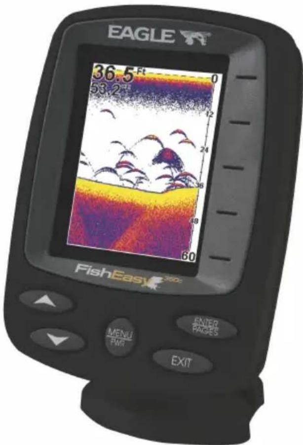
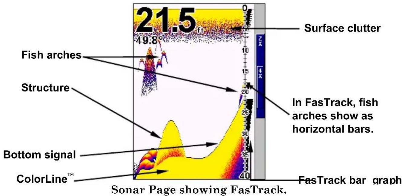
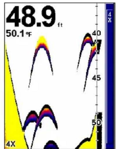
Full Sonar Chart
The Full Sonar Chart is unit's default mode. Depth scales on the right side of the screen aid in determining the depth of targets.
The line at the top of the screen represents the surface. The bottom depth and surface temperature (if equipped with a temperature sensor or a transducer with a temp sensor built in) are shown in the top left corner of the screen.
The FasTrack™ display is shown to the right of the depth scale. The zoom bar is to the right of the Fastrack display.

Split Zoom Sonar Chart
The right half of the Split Zoom Sonar Chart displays a typical sonar return. The left half of the chart, shows a zoomed view of the window of the right half. The zoom range (2X or 4X) is shown in the bottom left corner of the screen.
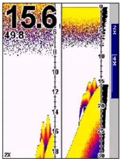

Split Zoom Sonar Chart. The first image (left) the left half of the screen is shown with a 2X zoom. In the second image (right), the left half of the screen is shown with a 4X zoom.
Digital Data/Chart
The Digital Data Chart displays five large digital boxes containing the following information: Water Depth, Surface Water Temperature, Temperature 2, Water Speed and Water Distance.
NOTE:
Temp 2 requires an additional (optional) temperature sensor.

Digital Data/Chart
Basic Sonar Quick Reference
- Mount the unit and install the transducer. Connect the unit to power.
- Launch your boat.
- To turn on the unit, press and release MENU key.
- Head for your fishing grounds. Your unit automatically displays digital depth and surface water temperature in the corner of the screen.
- As you're watching the sonar returns, you can change the display by:
Zoom in to enlarge the chart for more detail, or...
Zoom out to return to full chart mode.
Press MENU|ENT to select which Zoom Mode you want to use.
- If necessary, adjust sensitivity to improve chart readability. Press MENU|ENT and the Sensitivity Menu will appear on the left of your screen. Use and to change the setting.
- Watch the display for the appearance of fish arches. When you see arches, stop the boat and get your lure in the water.
- To get a more accurate measure of a target's depth, use the Depth Cursor. Press MENU to DEPTH CURSOR|ENT. Press to align the cursor line with the fish arch.
- If you are drifting at a very low speed or anchored and a fish swims through the transducer's signal cone, the fish echo will appear as a straight line.
- To turn off the unit, press and hold MENU key for three seconds.
Sensitivity
Sensitivity controls the unit's ability to pick up echoes.


Fig.1 Fig.2

Fig. 3 Fig. 4
These figures show results of different sensitivity levels on the same location. Fig. 1: Sensitivity at 87 percent, determined by Auto Sensitivity. Typical of full auto mode. Fig. 2: Sensitivity set at 50 percent. Fig. 3: Sensitivity set at 20 percent. Fig. 4: Sensitivity set at 100 percent.
Sensitivity has two modes, Automatic and Manual. Adjusting sensitivity in Auto Sensitivity Mode will allow you to increase sensitivity to 100 percent, but limits the minimum setting to allow for automatic bottom tracking. When you change the setting with auto turned on, the unit will continue to track the bottom and make minor adjustments to the sensitivity level with a bias toward your desired settings.
In Manual Mode, you can set sensitivity to 100 percent or 0 percent with no restrictions.
To switch Auto mode to Manual mode:
- Press MENU highlight AUTO SENSITIVITY and press ENT.
- Select SENSITIVITY and press ENT.
- Press to pick a different sensitivity setting. Press EXIT when it is set to a desired level.

Sensitivity Control Bar.
To adjust sensitivity:
- Press MENU|ENT.
- The Sensitivity Control Bar appears. Press to decrease sensitivity. Press to increase sensitivity.
- When it is set to a desired level, press EXIT.
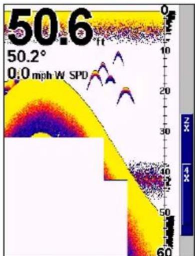
Fish Symbols vs. Full Sonar Chart
Fish I.D. is an easier way for a sonar novice to recognize a fish return when it appears on the screen. Locating fish by fish symbols does have some limitations.
Your sonar unit's microprocessor is powerful, but can be fooled. Some of the echoes shown as fish could be tree limbs or turtles. To see what's under your boat in maximum detail, we recommend you turn off Fish I.D. and begin learning to interpret fish arches.
Tip:
If you are going to be in another part of the boat or busy with another task, turn on Fish ID and set the audible fish alarm. An alarm will sound when a fish is detected by the unit.
Notes
Advanced Options & Features

FishEasy 350c.
ASPTM (Advanced Signal Processing)
The ASPTM feature is a noise rejection system that constantly evaluates the effects of boat speed, water conditions and electrical interference and automatically gives you the best display possible under most conditions. The ASP feature has four settings — Off, Low, Medium and High. If you have high noise levels, try using the "High" ASP setting.
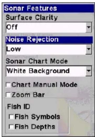
In the Sonar Features menu, Noise Rejection is selected with ASP in the default low setting.
To change the ASP level:
- From the Sonar Page, press MENU | to SONAR FEATURES | ENT.
- Press to NOISE REJECTION | ENT.
- Press or to select a setting, then press ENT.
- To return to the previous page, press EXIT | EXIT.
Alarms
This unit has two types of sonar alarms: a Fish Alarm and a Depth Alarm.
Fish Alarm
The Fish Alarm alerts you when the Fish I.D.™ feature recognizes an echo as a fish.
To turn the fish alarm on:
- Press MENU | MENU | ↓ to SONAR ALARMS | ENT.
- Press to FISH ALARM|ENT|EXIT|EXIT.
- To turn off the alarm, press MENU|MENU| to SONAR ALARMS|ENT| to FISH ALARM|ENT|EXIT|EXIT.

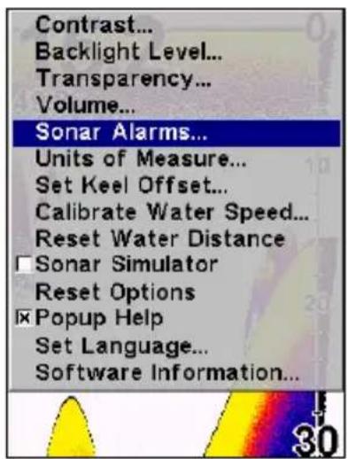
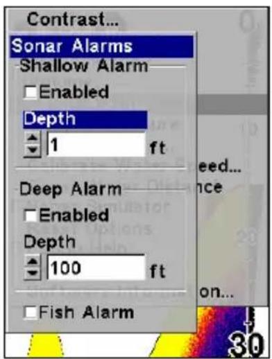
Sonar Alarms menu with Fish Alarm selected (left). Sonar alarms highlighted on Main Menu (center). Depth selected on Sonar Alarms menu (right).
Depth Alarm
The Depth Alarm has a Shallow and a Deep setting. The shallow alarm sounds an alarm tone when the bottom is shallower than the alarm's setting. The deep alarm sounds a tone when the bottom is deeper than the alarm's setting.
To turn on the shallow alarm:
- Press MENU | MENU | to SONAR ALARMS | ENT.
- Press ENT to access depth feature.
- Press or until the depth is correct, then press ENT.
- Press ↑ to SHALLOW ALARM ENABLED | ENT | EXIT | EXIT.
- To turn off the alarm, press MENU|MENU|to SONAR ALARMS|ENT|ENT|EXIT|EXIT.
To switch to a different depth setting, open the Sonar Alarms menu and repeat the instructions in step 3 above.
To turn on the deep alarm:
- Press MENU | MENU | ↓ to SONAR ALARMS | ENT.
- Press to DEEP ALARM DEPTH | ENT.
-
Press or until the depth is correct, then press ENT.
-
Press to DEEP ALARM ENABLED | ENT | EXIT | EXIT.
-
To turn off the alarm, press MENU|MENU|to SONAR ALARMS|ENT|to DEEP ALARM ENABLED|ENT|EXIT|EXIT.
Backlight Level
Turning the backlight will allow you to use the unit at night.
To adjust backlight level:
-
Press MENU|MENU|to BACKLIGHT LEVEL|ENT.
-
The BACKLIGHT LEVEL slider bar appears. Use to set the backlight to the desired setting. Press EXIT.
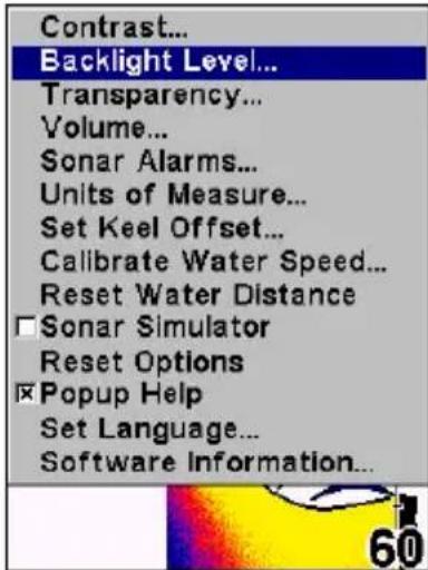

Backlight Level highlighted on main menu (left). Backlight Level control bar (right).
Calibrate Speed
If your GPS speed is different from your speed sensor, you can calibrate the speed sensor to offset the difference between the readings. If, for example, you figure the speed sensor is reading 10 percent faster than actual speed, you will input (-10) in the calibration window. If it is reading 10 percent slower, you will input (10).
To calibrate speed sensor:
-
Press MENU|MENU|to CALIBRATE WATER SPEED |ENT.
-
Input the number you calculated earlier: press to change the displayed number. Continue until the desired has been input and press EXIT.
Chart Speed
Chart Speed controls the rate sonar returns scroll across the screen. Decreasing Chart Speed is most beneficial when you are fishing from a stationary location.

Chart Speed control bar.
To change chart speed:
- From the Sonar page, press MENU| to CHART SPEED | ENT.
- The Chart Speed Control Bar appears. Press to decrease chart speed. Press to increase chart speed.
- Press EXIT to remove the Chart Speed control bar from the screen.
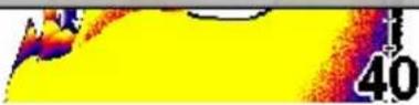
ColorLineTM
ColorLine helps you distinguish between strong and weak sonar returns. A soft, muddy or weedy bottom returns a weaker signal displayed as a narrow, colored line (dark blue tinged with red or a little yellow.) A hard bottom or other relatively hard target returns a strong signal which causes a wider brightly colored line (reddish yellow to bright yellow.) Fish are shown mostly as blue arches.
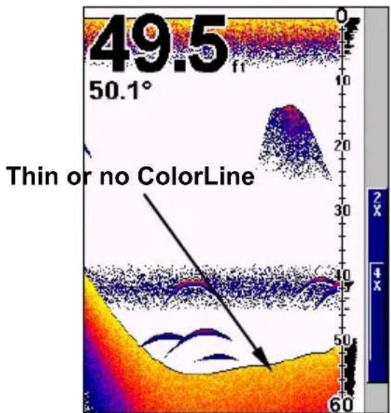
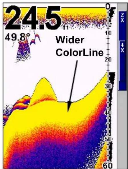
ColorLine shows a soft bottom, probably sand or mud (left). ColorLine shows a harder, rocky bottom (right).
To adjust ColorLine:
- From the Sonar Page, press MENU | ↓ to COLORLINE | ENT.
- The ColorLine Control Bar appears. Press to decrease ColorLine; press to increase ColorLine.
- Press EXIT to clear the Colorline control bar from the screen.
Contrast
To adjust contrast:
- Press MENU|MENU|ENT. The CONTRAST control bar will appear.
- Press to increase or decrease the contrast.
- Press EXIT to clear the Contrast control bar from the screen.


Contrast Command (left) and Contrast control bar (right).
Depth Cursor
The depth cursor consists of a horizontal line with a digital depth box on the right side. The numbers inside the box show the depth of the cursor.

Sonar chart with the depth cursor active. The line indicates the large fish is 40.52 feet deep.
To use Depth Cursor:
- From the Sonar Page, press MENU | to DEPTH CURSOR | ENT.
- Press to lower the cursor line. Press to raise the cursor line.
- Press EXIT to clear the Depth Cursor from the screen.
Depth Range - Automatic
When Automatic Depth Range is activated, the bottom signal is automatically placed in the lower half of the screen.
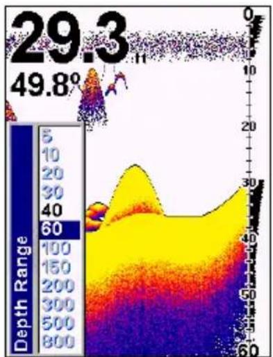
The Depth Range Control Scale.
To turn on Automatic Depth Range:
- From the Sonar Page, press MENU| to DEPTH RANGE|ENT. The Depth Range Scale appears.
- Press to select a different depth range. A blue bar highlights the selected range. Range numbers in gray cannot be selected.
- When the new range is selected, press EXIT to clear the menu.
Depth Range - Manual
You have complete control over Depth Range when the unit is in manual mode. There are 12 depth ranges, from 5 feet to 800 feet.
To switch to Manual Depth Range:
-
First, turn off Automatic Depth Range by pressing MENU| to AUTO DEPTH RANGE |ENT.
-
Press to DEPTH RANGE|ENT and the Depth Range Scale appears.
- Use to select a different depth range. A blue bar highlights the selected range.
- When the new range is selected, press EXIT to clear the menu.
FasTrackTM
FasTrack converts all echoes to short horizontal lines on the right side of the screen, giving you a rapid update of conditions directly under the boat.
Fish I.D.
The Fish I.D. feature displays fish returns as fish symbols rather than fish arches. While Fish I.D. makes fish easier to recognize, it also can be fooled because it can not distinguish between fish and other suspended objects such as trotlines, turtles, submerged floats, air bubbles, etc. You may see fish symbols on the screen when actually, there are no fish. Fish I.D. is on by default.
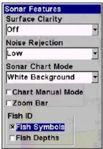
Sonar Features menu with Fish I.D. Symbols selected. When the check box to the left is checked, the feature is on.
To turn on Fish ID:
- From the Sonar Page, press MENU | ↓ to SONAR FEATURES | ENT.
- Press to FISH ID SYMBOLS | ENT | EXIT | EXIT.
- Repeat these instructions to turn off Fish I.D.
FishTrackTM
FishTrack displays the depth of a fish symbols, allowing you to gauge the depth of targets. FishTrack is available only when Fish I.D. is turned on. The default setting for FishTrack is off.
To turn on FishTrack:
- From the Sonar Page, press MENU | ↓ to SONAR FEATURES | ENT.
- Press to FISH ID DEPHS | ENT | EXIT | EXIT.
- Repeat these steps to turn off FishTrack. Turning off FishTrack in this manner will not turn off Fish I.D.


Sonar Features menu with Fish I.D. Depths selected. When the check box is checked, the feature is on (left). Sonar Page showing Fish I.D. symbols with FishTrack turned on (right).

Data list showing Water Speed selected for display on Sonar Page.
Overlay Data
To add or change Overlay Data:
- Press MENU | to OVERLAY DATA | ENT.
-
Press to select Data Type|ENT. A check mark will appear beside the data type you selected. Repeat Step 2 for each data type you want to display.
-
Press EXIT | EXIT to return to the main screen.
To remove Overlay Data:
- Press MENU | to OVERLAY DATA | ENT.
- Press to select the data type you want to remove and press ENT The check mark next to the data you selected will disappear.
- Press EXIT | EXIT to return to the previous page.
To change overlay data font size:
- Press MENU | to OVERLAY DATA | ENT.
- Press up to select a Data Type and press ENT. The DATA SIZE (displayed in the bottom of the Overlay Data Shown window) cycles through available sizes. Keep pressing ENT until it shows the desired Data Size, then press EXIT.
- To return to the previous page, press EXIT.
Sonar chart with Overlay Data turned on. This example shows Depth, Water Temperature and the Water Speed of the boat.
Ping Speed & HyperScroll™
Ping Speed controls the rate at which the transmitter and transducer broadcast sonar sound waves — pings — into the water. The unit has a default ping speed of 50 percent.
When you boost ping speed and switch into HyperScroll, the width of the FasTrack bar graph display doubles in width at the right side of the screen.

Ping Speed Control Bar at default setting.
To change Ping Speed:
- From the Sonar Page, press MENU | ↓ to PING SPEED | ENT.
- The Ping Speed Control Bar appears. Press to increase ping speed. Press to decrease ping speed.
- Press EXIT to return to the main screen.
To adjust Sensitivity:
- From the Sonar Page, press MENU|ENT.
- The Sensitivity Control Bar appears. Press to decrease sensitivity. Press to increase sensitivity.
- Press EXIT to return to the main screen.
To turn off HyperScroll:
1.From the Sonar Page,press MENU to PING SPEED|ENT.
2. The Ping Speed Control Bar appears. Press to decrease ping speed to 50 percent.
3. Press EXIT to return to the main screen.
Pop-up Help
With Pop-up help turned on, a pop-up message will appear when you hover over a menu item.
To turn on Pop-up Help:
-
Press MENU|MENU|to POPUP HELP.
-
Press ENT to check it (turn on) and uncheck it (turn off). Press EXIT to return to the main screen.

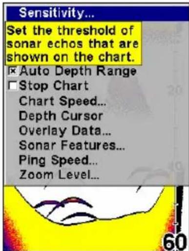
Main Menu with Pop-up Help command highlighted. At right, this example shows the Pop-up Help message for the Sensitivity command, located on the Sonar Menu.
Reset Options
Reset Options will switch all features, options and settings to factory default settings.
- Press MENU|MENU|to RESET OPTIONS|ENT.
- Highlight Yes and press ENT.
Reset Water Distance
The Digital Data page includes a window that shows distance traveled across the water (Water Distance). The Water Distance window can be reset to zero using the Reset Water Distance command.


At left, Main Menu with Reset Options command selected. On the right, Yes is selected for Reset all the options?
To reset Water Distance:
- Press MENU | MENU, highlight RESET WATER DISTANCE and press ENT.
- Press EXIT to return to the main screen.
Set Keel Offset
This unit measures water depth from the face of the transducer. If the transducer is 1 foot below the surface and the screen shows the water depth as 30 feet, the actual depth is 31 feet, since the transducer is the below the water surface. Keel Offset lets you calibrate the unit's depth indicators to account for the distance from the face of the transducer and the lowest part of the boat.
To set Keel Offset:
- Measure the distance from the face of the transducer to the lowest part of the boat. In this example, we will use 3.5 feet, which will be input as - 3.5 feet.
- Press MENU|MENU|to SET KEEL OFFSET|ENT.
- The Keel Offset dialog box appears. Press so the first character is negative (-) .
- Press until the number shows - 3.5 and press EXIT.
Set Language
This unit supports 10 languages: English, French, German, Spanish, Italian, Danish, Swedish, Russian, Dutch and Finnish.
To select a language:
- Press MENU|MENU|to SET LANGUAGE|ENT.
- Use to select the desired language and press ENT.
Software Version Information
You can find out what software version your unit is using by accessing the Software Information screen.
- Press MENU | MENU | to SOFTWARE INFO | ENT. The software information will appear on the screen.
- Press EXIT|EXIT to return to the main screen.
Sonar Chart Mode
The default color scheme for the sonar chart is white background, but you also can change it to grayscale, reverse grayscale, blue background, night view, ice view or bottom color tracking.
To change sonar chart mode:
- From the Sonar Page, press MENU | ↓ to SONAR FEATURES | ENT.
- Press to SONAR CHART MODE | ENT.
- Press to desired mode | ENT.
- Press EXIT|EXIT to return to the Sonar Page.
Sonar Simulator
The FishEasy 350c has a simulator that allows you to practice using the unit before taking it out on the water.
To use the simulator:
- Press MENU | MENU. Highlight SONAR SIMULATOR and press ENT.
- Repeat Step 1 to turn off the simulator.
Stop Chart
The Stop Chart feature turns off the sonar and stops the chart from scrolling.
To use Stop Chart feature:
-
Press MENU | ↓ to STOP CHART | ENT.
-
Repeat Step 1 to resume normal chart operation.
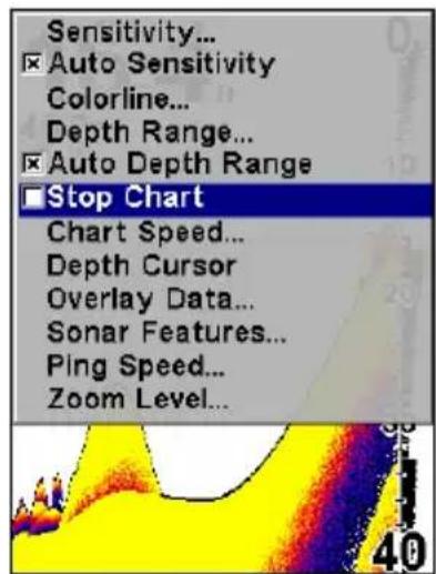

Sonar Menu with Stop Chart command selected (left). The box is unchecked, indicating that the chart is scrolling across the screen. Sonar Features menu with Surface Clarity selected (right).
Surface Clarity
To reduce the level of surface clutter on the display, access Surface Clarity from the Sonar Features menu. There are three levels of surface clarity: low, medium, or high. The default level is off.
To adjust the Surface Clarity:
-
From the Sonar Page, press MENU | to SONAR FEATURES | ENT | ENT.
-
Press or to select clarity level|EXIT|EXIT|EXIT.


In the illustration at left, Surface Clarity is turned off. The right view shows Surface Clarity set at High.
Transparency
The transparency feature gives you control over the transparency of menus. If you want to be able to monitor the sonar chart while working with a menu, use a high transparency level.

Main Menu with Transparency command selected.
To adjust Menu Transparency:
- Press MENU|MENU| to TRANSPARENCY|ENT. The Transparency control bar will appear.
- Use to select the desired transparency level.
- Press EXIT to clear the control bar from the screen.
Units of Measure
Access the Units of Measure menu to select the units of measure for speed and distance (statute or nautical miles, meters), depth (feet, fathoms, or meters) and temperature (degrees Fahrenheit or Celsius).
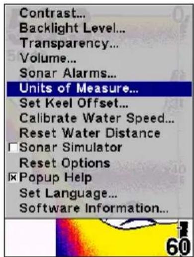

Main Menu, left, Units of Measure Menu, right.
To select Units of Measure:
- Press MENU | MENU | to UNITS OF MEASURE | ENT.
- Press to the desired unit and press ENT.
- Press EXIT | EXIT to return to the page display.
Volume
This function is used to adjust speaker volume.
To adjust volume:
- Press MENU|MENU|to VOLUME|ENT.
- Use to set volume at the desired level. Press EXIT to return to the main screen.
Zoom & Zoom Bar
You will use the Zoom feature to enlarge echoes on the screen. There are two zoom options: 2X and 4X.

Sonar Page with 2X zoom (left). Sonar Page with 4X zoom (right).
To zoom in:
- Press MENU | to ZOOM LEVEL | ENT. The Zoom Level menu appears.
- Press to select the desired zoom level and press ENT.
- Press EXIT to clear the menu.
To turn on the Zoom Bar:
- Press MENU | ↓ to SONAR FEATURES | ENT.
- The Sonar Features menu appears. Press to ZOOM BAR | ENT.
- Press EXIT | EXIT to return to the main screen.
- To turn off the Zoom Bar, repeat steps 1 and 2.
Zoom Pan
Zoom Pan allows you to zoom in on any portion of the water column.
To use Zoom Pan:
- Switch the unit to manual depth Range and turn on 2X or 4X Zoom.
- Press to pan up and down the water column.
Index
A
Accessories, 1, 5, 14, 23, 24
Accessory, 22, 24, 25
Alarms, 1, 33, 44, 45, 46
ASPTM (Advanced Signal Processing), 1, 43
B
Backlights / Lighting, 1, 3, 33, 46
Batteries, 1, 5, 22, 23, 27, 28, 32
Bracket installation, 14
C
Calibrate Speed, 1, 46
Chart Speed, 1, 34, 47
Contrast, 1, 33, 48, 49
Cursor, 4, 35, 38, 49, 50
D
Depth Cursor, 2, 4, 35, 38, 49, 50
Depth Range, 34, 36, 50, 51, 62
Display Options, 35, 36, 37, 41
F
FasTrackTM, 2, 51
Fish Alarm, 41, 44
Fisharches,15
Fish Depths, 2, 52
Fish I.D. TM 2,35,44,51
Fish Symbols, 2, 35, 41, 44, 51
FishTrackTM, 2, 52
Frequency, 3
H
HyperScrollTM, 2, 54
I
Installation, 1, 5, 14, 20, 23, 24, 27
Introduction
K
Keel Offset, 2, 33, 57
Keyboard, 1, 4, 31
Keypad Description, 1, 4
L
Languages, 2, 34, 58
M
Main Menu, 32, 33, 34, 45, 56, 57, 60, 61
N
Noise Rejection, 44
0
Overlay Data, 2, 35, 53, 54
P
Page Displays, 1, 4, 32, 35
Ping Speed, 2, 35, 54, 55
Pop-upHelp,2,56
Power, 1, 3, 4, 5, 22, 23, 24, 25, 27, 28,
32, 38
Product Specifications, 1, 3
R
Range, 34, 36, 50, 51, 62
Repeat Play List, 52, 53, 58, 59
Reset Options, 2, 33, 56, 57
Reset Water Distance, 2, 33, 56, 57
Route, 5, 7, 13, 14, 15, 20, 22, 29
S
Searching, 20
Sensitivity, 1, 38, 39, 40, 55, 56
Simulator, 2, 33, 58
Software Version Information, 2, 58
SonarChartColorMode,2,58
SonarChartDisplayOptions,35,36,37 41
Sonar Menu, 32, 34, 56, 59
Sonar Operation
Speaker, 61
Speed Sensors, 1, 4, 17, 20, 21, 33, 46
StopChart,2,34,59
Surface Clarity, 2, 59, 60
T
Temperature Sensors, 1, 4, 17, 18, 19, 35
Transducer, 1, 3, 4, 5, 6, 7, 8, 9, 10, 11, 12, 13, 14, 15, 16, 18, 19, 20, 22, 23, 24, 25, 27, 28, 29, 35, 38, 54, 57
Transducer Location, 6
Trolling Motor Mount, 14
U
Units of Measure, 2, 33, 61
Z
Zooming, 2, 4, 35, 36, 37, 38, 62
Zoom Bar, 62
Zoom Pan, 2, 62
Table des Matieres
Informations Techniques: FishEasy 350C. 3
Installation & Accessoires 7
Accessoires, i, 7, 23, 25, 27, 28, 29, 30
Affichages,i,43
Aide, ii, 76, 77
Alarmes, i, ii, 4, 40, 56, 57, 58, 59
Alimentation, 3, 7, 25, 26, 27, 28, 30, 32, 33, 34, 38, 47
C
Installation, i, 7, 8, 10, 11, 12, 17, 23, 24, 25, 26, 27, 28, 32, 35
Luminosite, 39, 59, 60
M
MenuPrincipal,i,37,38,39,40,77 83,91,92
P
Piles, 7, 25, 26, 27, 32, 33, 34, 38
R
ReinitialisationdesOptions,77,78 80
Retro-éclairage/Eclairage, ii, 3, 59, 60, 78
S
"We," "our," or "us" refers to EAGLE ELECTRONICS, a division of NAVICO, the manufacturer of this product. "You" or "your" refers to the first person who purchases this product as a consumer item for personal, family, or household use.
We warrant this product against defects or malfunctions in materials and workmanship, and against failure to conform to this product's written specifications, all for one (1) year from the date of original purchase by you. WE MAKE NO OTHER EXPRESS WARRANTY OR REPRESENTATION OF ANY KIND WHATSOEVER CONCERNING THIS PRODUCT. Your remedies under this warranty will be available so long as you can show in a reasonable manner that any defect or malfunction in materials or workmanship, or any non-conformity with the product's written specifications, occurred within one year from the date of your original purchase, which must be substantiated by a dated sales receipt or sales slip. Any such defect, malfunction, or non-conformity which occurs within one year from your original purchase date will either be repaired without charge or be replaced with a new product identical or reasonably equivalent to this product, at our option, within a reasonable time after our receipt of the product. If such defect, malfunction, or non-conformity remains after a reasonable number of attempts to repair by us, you may elect to obtain without charge a replacement of the product or a refund for the product. THIS REPAIR, OR REPLACEMENT OR REFUND (AS JUST DESCRIBED) IS THE EXCLUSIVE REMEDY AVAILABLE TO YOU AGAINST US FOR ANY DEFECT, MALFUNCTION, OR NON-CONFORMITY CONCERNING THE PRODUCT OR FOR ANY LOSS OR DAMAGE RESULTING FROM ANY OTHER CAUSE WHATSOEVER. WE WILL NOT UNDER ANY CIRCUMSTANCES BE LIABLE TO ANYONE FOR ANY SPECIAL, CONSEQUENTIAL, INCIDENTAL, OR OTHER INDIRECT DAMAGE OF ANY KIND.
Some states do not allow the exclusion or limitation of incidental or consequential damages, so the above limitations or exclusions may not apply to you.
This warranty does NOT apply in the following circumstances: (1) when the product has been serviced or repaired by anyone other than us; (2) when the product has been connected, installed, combined, altered, adjusted, or handled in a manner other than according to the instructions furnished with the product; (3) when any serial number has been effaced, altered, or removed; or (4) when any defect, problem, loss, or damage has resulted from any accident, misuse, negligence, or carelessness, or from any failure to provide reasonable and necessary maintenance in accordance with the instructions of the owner's manual for the product.
We reserve the right to make changes or improvements in our products from time to time without incurring the obligation to install such improvements or changes on equipment or items previously manufactured.
This warranty gives you specific legal rights and you may also have other rights which may vary from state to state.
REMEINDER: You must retain the sales slip or sales receipt proving the date of your original purchase in case warranty service is ever required.
EAGLE ELECTRONICS PO BOX 669, CATOOSA, OK 74015 (800) 324-1354
How to Obtain Service...
...in the USA:
We back your investment in quality products with quick, expert service and genuine Eagle replacement parts. If you're in the United States and you have technical, return or repair questions, please contact the Factory Customer Service Department. Before any product can be returned, you must call customer service to determine if a return is necessary. Many times, customer service can resolve your problem over the phone without sending your product to the factory. To call us, use the following toll-free number:
800-324-1354
8 a.m. to 5 p.m. Central Standard Time, M-F
Eagle Electronics may find it necessary to change or end our shipping policies, regulations, and special offers at any time. We reserve the right to do so without notice.
...in Canada:
If you're in Canada and you have technical, return or repair questions, please contact the Factory Customer Service Department. Before any product can be returned, you must call customer service to determine if a return is necessary. Many times, customer service can resolve your problem over the phone without sending your product to the factory. To call us, use the following toll-free number:
800-661-3983
905-629-1614 (not toll-free)
8 a.m. to 5 p.m. Eastern Standard Time, M-F
...outside Canada and the USA:
If you have technical, return or repair questions, contact the dealer in the country where you purchased your unit. To locate a dealer near you, visit our web site, www.eaglesonar.com and look for the Dealer Locator.
Accessory Ordering Information for all countries
To order Eagle accessories such as power cables or transducers, please contact:
1) Your local marine dealer or consumer electronics store. Most quality dealers that handle marine electronic equipment or other consumer electronics should be able to assist you with these items.
To locate an Eagle dealer near you, visit our web site, www.eaglesonar.com and look for the Dealer Locator. Or, you can consult your telephone directory for listings.
2) U.S. customers: LEI Extras Inc., PO Box 129, Catoosa, OK 74015-0129
Call 1-800-324-0045 or visit our web site www.lei-extras.com.
3) Canadian customers can write:
Lowrance/Eagle Canada, 919 Matheson Blvd. E. Mississauga, Ontario L4W2R7 or fax 905-629-3118.
Shipping Information
If it becomes necessary to send a product for repair or replacement, you must first receive a return authorization number from Customer Service. Products shipped without a return authorization will not be accepted. When shipping, we recommend you do the following:
- Please do not ship the knobs or mounting bracket with your unit.
- If you are sending a check for repair, please place your check in an envelope and tape it to the unit.
- For proper testing, include a brief note with the product describing the problem. Be sure to include your name, return shipping address and a daytime telephone number. An e-mail address is optional but useful.
- Pack the unit in a suitable size box with packing material to prevent any damage during shipping.
- Write the Return Authorization (RA) number on the outside of the box underneath your return address.
- For your security, you may want to insure the package through your shipping courier. Eagle does not assume responsibility for goods lost or damaged in transit.
Visit our web site:

www.eaglesonar.com
Eagle Pub. 988-0143-97A Copyright © 2008
All Rights Reserved
Printed in USA
LEI-Eagle


- Copyright © 2008 Navico All rights reserved.
- Table of Contents
- NOTICE!
- Capabilities and Specifications: FishEasy 350C General
- Sonar
- Sonar sounding
- How to use this manual: typographical conventions Arrow Keys
- Keyboard
- Menu Commands
- Instructions = Menu Sequences
- Installation & Accessories
- Preparations
- Caution:
- Transducer Installation
- NOTE:
- Single-frequency transom installations
- Dual-frequency transom installations
- Single-frequency trolling motor installations
- Selecting a Transducer Location
- How low should you go?
- Transom Transducer Assembly And Mounting
- Assembling the bracket.
- Aligning the transducer on the transom.
- Assembling the transducer.
- Drilling mounting holes.
- Attaching transducer to transom.
- WARNING:
- Trolling Motor Bracket Installation (single-frequency only)
- Transducer Orientation and Fish Arches
- Speed/Temperature Sensors
- Speed Sensor Installation
- To install speed sensor:
- Power Connections
- Power and transducer connections for the FishEasy 350C sonar unit (direct battery connection shown).
- Bracket Installation
- Installing the bracket:
- Using the Quick Release Mounting Bracket
- Portable Sonar Installation
- Installing the Batteries
- Portable Transducer Assembly
- Notes
- Basic Sonar Operation
- MENU/PWR
- To access the Sonar menu:
- Sonar Menu
- Pages
- To access Pages:
- Full Sonar Chart
- Split Zoom Sonar Chart
- Digital Data/Chart
- Basic Sonar Quick Reference
- Sensitivity
- To switch Auto mode to Manual mode:
- To adjust sensitivity:
- Fish Symbols vs. Full Sonar Chart
- Tip:
- Advanced Options & Features
- ASPTM (Advanced Signal Processing)
- To change the ASP level:
- Alarms
- Fish Alarm
- To turn the fish alarm on:
- Depth Alarm
- To turn on the shallow alarm:
- To turn on the deep alarm:
- Backlight Level
- To adjust backlight level:
- Calibrate Speed
- To calibrate speed sensor:
- Chart Speed
- To change chart speed:
- ColorLineTM
- To adjust ColorLine:
- Contrast
- To adjust contrast:
- Depth Cursor
- To use Depth Cursor:
- Depth Range - Automatic
- To turn on Automatic Depth Range:
- Depth Range - Manual
- To switch to Manual Depth Range:
- FasTrackTM
- Fish I.D.
- To turn on Fish ID:
- FishTrackTM
- To turn on FishTrack:
- Overlay Data
- To remove Overlay Data:
- To change overlay data font size:
- Ping Speed & HyperScroll™
- To change Ping Speed:
- To turn off HyperScroll:
- Pop-up Help
- To turn on Pop-up Help:
- Reset Options
- Reset Water Distance
- To reset Water Distance:
- Set Keel Offset
- To set Keel Offset:
- Set Language
- To select a language:
- Software Version Information
- Sonar Chart Mode
- To change sonar chart mode:
- Sonar Simulator
- To use the simulator:
- Stop Chart
- To use Stop Chart feature:
- Surface Clarity
- To adjust the Surface Clarity:
- Transparency
- To adjust Menu Transparency:
- Units of Measure
- To select Units of Measure:
- Volume
- To adjust volume:
- Zoom & Zoom Bar
- To zoom in:
- To turn on the Zoom Bar:
- Zoom Pan
- To use Zoom Pan:
- Index
- A
- B
- C
- D
- F
- H
- I
- K
- L
- M
- N
- 0
- P
- R
- S
- T
- U
- Z
- Table des Matieres
- How to Obtain Service...
- ...in the USA:
- 800-324-1354
- ...in Canada:
- 800-661-3983
- ...outside Canada and the USA:
- Accessory Ordering Information for all countries
- Shipping Information
Brand : EAGLE
Model : FishEasy 350C Portable
Category : Fish finder