Typhoon 530 - Lawn mower Morrison - Free user manual and instructions
Find the device manual for free Typhoon 530 Morrison in PDF.

| Brand | Morrison |
| Model | Typhoon 530 |
| Product type | Self-propelled lawn mower |
| Engine | 4-stroke |
| Engine oil capacity | Approximately 600 ml, SAE 30 |
| Fuel | Unleaded gasoline, octane rating ≥ 91 |
| Fuel tank | Allow 5 mm air gap when filling |
| Cutting height | Central lever adjustment |
| Drive type | Self-propelled with handle |
| Speed variator | Yes, 8 positions (depending on model) |
| Safety | Operator presence handle (dead man's handle) |
| Grass catcher | Soft, rigid plastic or Aero Catcher depending on model |
| Blade type | Bar, Quick Cut, Quadcut or mulching depending on equipment |
| Center blade tightening torque | 45-50 Nm |
| Mulching | Optional mulching kit |
| Cleaning | Cyclowash connection on some models |
| Handlebar | Foldable, height adjustable (Ergo) |
| Starting | Manual (pull cord) or electric depending on model |
| Battery (electric start) | Recharges during use; external charger 15V max, 3A |
| Maintenance | Oil change every 50h, air filter every 25h, spark plug every 100h |
| Engine warranty | Warranted by the engine manufacturer, not by Morrison |
Frequently Asked Questions - Typhoon 530 Morrison
User questions about Typhoon 530 Morrison
0 question about this device. Answer the ones you know or ask your own.
Ask a new question about this device
Download the instructions for your Lawn mower in PDF format for free! Find your manual Typhoon 530 - Morrison and take your electronic device back in hand. On this page are published all the documents necessary for the use of your device. Typhoon 530 by Morrison.
USER MANUAL Typhoon 530 Morrison
This manual covers a range of different Morrison Mowers. Some features mentioned may not apply to your mower.
Important: Keep these instructions and the engine booklet in a safe place for future reference. They contain important information about your mower.
HANDLEIDING

Head Office - New Zealand
1-37 Mt Wellington Highway. Panmure,
P.O.Box 14 349
Auckland 1060.
Revised November 2009
EXPLANATION OF SYMBOLS
1.
2.
3.
4.
5.
6.
7.


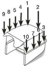
GBR
Read Owner's Manual1.
Keep bystanders away.2. Drive Clutch3.
Operator Presence Control Bail4. Caution rotating blade-keep hands 5. and feet clear.
Remove Spark Plug.6. Variable Speed Drive Control7.
FRA
SAFETY INSTRUCTIONS 4
ASSEMBLING THE MOWER 5
PREPARING THE ENGINE 5
RUNNING THE ENGINE 6
STARTING 6
STOPPING 7
DRIVE CONTROLS
THE GRASS CATCHER 7
MOWING ADVICE 9
THE MULCHING BLOCK 10
CHIPPER MOWERS 10
AFTER MOWING 10
BLADES 10
MAINTENANCE 11
TROUBLESHOOTING 11
THIS MANUAL COVERS A RANGE OF DIFFERENT MOWERS. SOME FEATURES MENTIONED MAY NOT APPLY TO YOUR MOWER.
IMPORTANT: Keep these instructions and the engine booklet in a safe place for future reference. They contain important information about your mower.

CAUTION
A CAUTION INDICATES SPECIAL PRECAUTIONS THAT MUST BE TAKEN TO AVOID DAMAGE TO THE MOWER.

WARNING
A WARNING INDICATES SPECIAL PROCEDURES THAT MUST BE FOLLOWED TO AVOID INJURY TO THE OPERATOR OR ANY BYSTANDER.
SAFETY
INSTRUCTIONS


PLEASE READ ALL INSTRUCTIONS BEFORE ATTEMPTING TO USE YOUR MOWER.
TRAINING
- Read the operating and maintenance manuals carefully. Be thoroughly familiar with the controls and the proper use of the equipment. Know how to stop the mower and disengage the controls quickly in an emergency.
- Never allow children or people unfamiliar with these instructions to operate the mower.
- Keep the area of operation clear of all persons, particularly small children and pets.
PREPARATION
- Thoroughly inspect the area where the equipment is to be used and remove all stones, sticks, wires, bones and other foreign objects before mowing, they could be thrown by the blade.
- Do not operate the equipment when barefoot
or wearing open sandals. Always wear substantial footwear and long trousers. It is advisable to wear suitable eye protection.
- Check the fuel before starting the engine. Do not smoke while fuelling the engine. Do not fill the fuel tank indoors, never remove the fuel cap off the fuel tank or add fuel when the engine is running or until it has been allowed to cool for several minutes after running. Clean off any spilled fuel before starting the engine.
- Never attempt to make a wheel height adjustment while the engine is running.
- Mow only in daylight or good artificial light, and always keep children away from the mowing area.
- Never operate the equipment in wet grass. Always be sure of your footing; keep a firm hold on the handle and walk; never run. Never walk backwards while cutting grass.
OPERATION
- Disengage all blade and drive controls before starting the engine.
- Do not tilt the mower when starting the engine.
- Start the engine carefully with feet well away from the blades.
- Do not put hands or feet near or under rotating parts. Always keep clear of the blade and discharge opening.
- Do not change the engine governor settings or over-speed the engine. Excessive speed is dangerous and shortens mower life.
6 Stop the engine when crossing gravel drives, walks or roads. -
Don't mow over heavy or solid objects as striking them with the blade can cause serious damage to the engine and will void your warranty.
-
After striking a foreign object, stop the engine, remove the wire from the spark plug, thoroughly inspect the mower for any damage, and repair the damage before restarting and operating the mower.
-
If the mower should start to vibrate abnormally, stop the engine, disconnect the spark plug wire, and check immediately for the cause. Vibration is generally a warning of trouble.
- Stop the engine whenever you leave the mower, even for a moment, before cleaning the mower housing, and when making any repairs or inspections.
- When cleaning, repairing or inspecting, make certain the blade and all moving parts have stopped and that the engine has had time to cool. Disconnect the spark plug wire, and keep the wire away from the plug to prevent accidental starting.
- Do not run the engine indoors. Lethal exhaust gases can be produced.
- Shut the engine off and wait until the blade comes to a complete stop before removing the grass catcher or unclogging the chute.
- Mow across the face of slopes; never up and down. Exercise extreme caution when changing direction on slopes. Do not mow excessively steep slopes.
- Never operate the mower without proper guards, deflectors provided by the manufacturer, or other safety devices in place.
-
Never pick up or carry a mower when it is operating.
-
Where a fuel tap is fitted, turn it off at the conclusion of mowing and reduce the throttle setting during runout.
MAINTENANCE
- Before using, check the blade(s) and blade bolt(s) for wear and damage. Replace worn or damaged blades and bolts in sets to preserve the balance. DAMAGED BLADES AND WORN BOLTS ARE MAJOR HAZARDS.
-
Keep all nuts, bolts and screws tight to be sure the mower is in safe working condition.
-
Never store the mower with fuel in the tank inside a building where fumes may reach an open flame or spark. Allow the engine to cool before storing in any enclosure.
-
Store fuel in an approved container safely out of the reach of children in a cool, well ventilated place.
- To reduce fire hazard, keep the engine free of grass, leaves, or excessive grease.
- Check the catcher bag frequently for deterioration and wear, and replace worn bags. Check that replacement bags comply with the original manufacturer's recommendations or specifications.
STORING THE MOWER
The handle can be folded to minimise space requirements.
FOLDING THE HANDLE. Loosen the clamp knobs or unlock the handle lever(s) in the middle of the handle and fold the top section over the engine.
Ergo Shift models can also be stored by moving the handle to the upright position.

CAUTION
Check that the control cables are not being strained while folding and unfolding the handle. Permanent kinks will make the controls difficult to operate.
TIPPING THE MOWER SAFELY FOR STORAGE OR INSPECTION.

CAUTION
Tilting the mower-Drain fuel, then tilt the mower with the spark plug uppermost. Remove the spark plug lead.
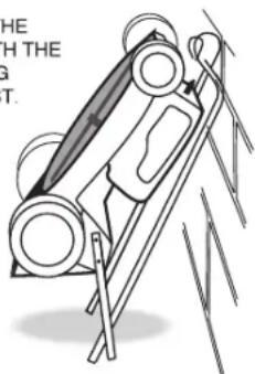
ONLY TILT THE
MOWER WITH THE
SPARK PLUG
UPPER MOST.
ASSEMBLING THE MOWER
Please refer to the following sections when preparing the mower for its first use.
Fitting the handle
Preparing the Engine
Assembling the catcher
NOTE - The left and right sides of the mower are referred to as viewed from the operating position behind the handle.
FITTING THE HANDLE
In some cases the handle may be completely detached from the mower body although the upper handle may be connected by the throttle control cable. Carefully remove the mower and handles from the box together to avoid damaging the throttle control cable.
Assembling the 'Screw Lock' Handle.
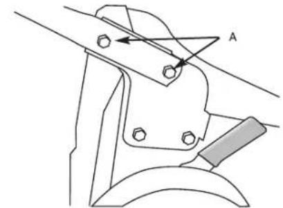
The lower handle is fitted to the mower using the four bolts located in the handle brackets, tow on each side, 'A' in the drawing below. To bolt the lower handle to the mower fit the bolts through the lower handle then fit the handle to the mower body and tighten the nuts on the inside of the mounting brackets using a 13mm A/F socket or spanner.
Now attach the upper handle to the lower handle.

CAUTION
Take care not to rotate the handle before fitting it, as this will tangle the control cable(s).
Fit the two long bolts through the holes in the lower handle from the inside with the round heads snug against the tube. Fit the holes in the upper handle over the two long bolts. Make sure that the throttle control is located on the right hand side. Attach the plastic knob to the outside of the lower handle bolt as shown below and tighten by hand until the upper handle is locked in position.
Assembling the 'Cam Lock' Handle.
Most of these models are fully assembled when packed, so all that is needed is to remove them from the carton, swing the handle to the operating position and lock the handle lever(s).
The camlock handles on some mowers are reversed for shipping. To turn them around unwind the nut to the end of the thread with a 13mmA/F spanner/socket, pull the camlock handle outwards and rotate it 180^ . Relighten the nut until the handle locks firmly in place and it does not change position when in use.
Locked position when Shipped.
The correct locked position after refitting.
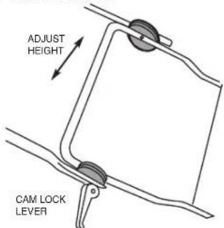
THE 'ERGO' HANDLE
The 'Ergo' handle can be adjusted to your preferred height. Simply release both cam lock levers, move the upper handle to the height required and re-clamp the cam locks. Where the mower has screw type locks, wind the knobs firmly clockwise to lock the handle.
Ergo Shift
Some handles can be rotated forward to give easy access to the rear flap. Depress the foot lever 1 and push the handle until you feel resistance—in a near vertical position 2. The handle can be moved back to the mowing position without using the foot lever.
PREPARING THE ENGINE

PLEASE READ AND UNDERSTAND THE ENGINE MANUFACTURERS ENGINE OWNERS MANUAL PRIOR TO OPERATING THE LAWNMOWER.

CAUTION
DO NOT START your four stroke engine before making sure that it has been filled with the right amount of the correct grade of oil. See engine instruction book for details.
TWO STROKE ENGINES require no special attention to lubrication provided that the fuel/oil mixture is correct at all times.
OIL
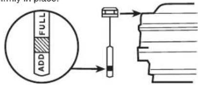
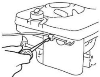
Four stroke (cycle) engines are shipped without oil. Place the mower on a level position, unscrew the 'OIL FILL' cap and slowly pour oil into the sump. Fill to the full mark on the dipstick. The capacity is approximately 600 ml. Use SAE 30 engine oil. When checking the oil level, and before running the engine, screw the dipstick firmly in place.
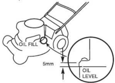
Checking the oil level if the engine is not fitted with a dip stick.
CHANGING THE ENGINE OIL
FOUR STROKE ENGINES should be checked for oil level every 8 hours running (or daily), and the oil should be drained and replaced after every 50 hours of use.
FUEL


WARNING
PETROL VAPOUR IS HIGHLY FLAMMABLE AND EXPLOSIVE. HANDLE WITH EXTREME CARE. STORE IN AN APPROVED CONTAINER. DO NOT FILL TANK WHEN ENGINE IS RUNNING OR IS STILL HOT. DO NOT ALLOW OPEN FLAME, MATCHES OR SMOKING NEARBY. FILL TANK OUTDOORS IN A WELL VENTILATED AREA. WIPE AWAY ANY SPILLS AND MOVE THE MOWER AWAY FROM ANY PETROL FUMES BEFORE STARTING ENGINE.

CAUTION
If a blue plug is fitted beneath the petrol filler cap it must be discarded. It is for transportation purposes only.
For two stroke engines fuel ratio, refer to engine instruction book.
When filling the fuel tank, always leave an air space of about 5mm to allow for expansion of the fuel.

CAUTION
USE ONLY CLEAN FRESH PETROL AT ALL TIMES, preferably un-leaded, with an octane rating of at least 91. Four stroke (cycle) engines use straight fuel. Two stroke engines MUST have a fuel and oil mixture. See engine instruction book for details. Always mix two-stroke fuel thoroughly by shaking the oil and petrol together in a clean container before pouring into the engine tank. USE ONLY TWO STROKE CYCLE OILS when mixing two stroke fuel. We do not recommend the use of multi-viscosity oils or pre-mixed fuels.
ENGINE
Regular attention to a few simple items will ensure long and trouble-free service from your mower. Carry out the regular maintenance described in the engine manual, and check the engine mounting bolts regularly to be sure they are tight.
NOTE: THE ENGINE IS WARRANTED BY THE ENGINE MANUFACTURER AND NOT MORRISON. YOUR SPECIALIST MORRISON SERVICE DEALER CAN ASSIST WITH ENGINE RELATED WARRANTY MATTERS.

WARNING
Before making any adjustments to your mower make sure that the engine is turned off and that the blade has STOPPED ROTATING. Always disconnect the spark plug wire and make sure it cannot accidentally contact the spark plug before touching anything under the mower housing.
RUNNING THE ENGINE
ENGINE CONTROL
This is mounted at the top of the handle. It operates the choke, if fitted (for cold starting) and allows you to set the governed speed of the engine.
On all models push control forward for full throttle.
You will not need to change the control setting constantly while mowing because the governor holds the selected speed, even under varying cutting loads. The positions for CHOKE (cold start), FAST, SLOW and STOP are usually marked. If STOP is not marked, move the lever beyond SLOW to stop the engine.
NOTE: Some models are fitted with an Operator Presence Control (OPC) bail at the top of the handle. This must be squeezed against the handlebar before starting the engine. The engine will stop immediately when the bail is released.
Some controls have symbols instead of words. On these,
means CHOKE
means FAST,
means SLOW,
Means STOP
If your engine control does not have the word CHOKERChoke symbol you have a Pulsa Prime engine. (See RUNNING THE ENGINE, MANUAL START MODELS
ENGINE CONTROL. This MUST be correctly adjusted for easy starting and safe stopping. If you have cold starting problems, adjust the outer sleeve of the control cable under the clamp on the engine at the lower end of the cable. See engine instruction booklet for details. Make any adjustments only with the handle in its normal operating position. After adjusting, check that the choke butterfly fully closes at one end of the control lever travel, and that the ignition stop switch is activated at the other.
STARTING
Ensure that the engine has been prepared correctly (see above) and that the fuel tap (if fitted) is turned ON. We recommend that you check the oil level before every mowing session.

WARNING
NEVER RUN THE ENGINE INDOORS OR IN POORLY VENTILATED AREAS. ENGINE EXHAUST CONTAINS CARBON MONOXIDE, AN ODOURLESS AND DEADLY GAS. KEEP HANDS, FEET, HAIR AND LOOSE CLOTHING AWAY FROM MOVING PARTS.
MANUAL START MODELS. If the engine has not been running recently, set the engine control to the CHoke position. For Pulsa Prime engines (which have no CHoke marking or symbol on the control), push the primer bulb on the side of the engine by the carburettor, refer engine owner's manual. (Do this also if you have just refilled the tank after running out of fuel). Stand to the right of the mower and place your foot on the mower body, grasp the starter grip, pull slowly until a resistance is felt and then pull forcefully to prevent kick-back. Repeat until the engine starts. Do not pull the cord with a jerk or release it until fully rewound. When the engine starts and has warmed up for a short time, move the control to the desired speed. Should the engine not start due to 'flooding', move the control to SLOW and pull the starter six times to clear the flooding.

ELECTRIC START MODELS.

Follow the procedure for manual start models, remembering not to use the choke when the engine is warm. Instead of pulling the starter grip, simply stand at the handle and turn the key fully clockwise. When the engine starts, release the key. It will spring back.
Avoid operating the starter for long periods to prevent excessive battery drain. For best starter life, crank no more than a few seconds at a time
and no more than 15 seconds in any minute. If the battery is discharged and the starter will not operate, the mower may be started manually as described previously. You need to mow continuously for approximately 20 minutes to recharge the battery.

WARNING
OPERATING THE STARTER ROTATES THE CUTTING BLADES - KEEP HANDS AND FEET WELL CLEAR.
When the engine starts and has warmed up for a short time, move the control to the desired speed. Should the engine not start due to 'flooding', move the control to SLOW and pull the starter six times to clear the flooding.

BATTERY

WARNING
Batteries contain corrosive fluids and toxic materials and should be handled with care. Keep away from children. Do not puncture, disassemble, mutilate or incinerate. Use in a well ventilated area as explosive gases can be vented during charge or discharge. Do not make direct contact between the terminals as this will create excessive heat and possibly a fire.
The engine on an electric start mower charges the battery as you mow, so no special attention is needed. If the battery should require extra charging, use only a charger which has a well regulated constant voltage (15 volts max) with a maximum current of 3 Amps. Full charging will take 3 hours with a 3 Amp charger, or overnight with the usual 'trickle' charger. If your mower is not being used regularly, we recommend an overnight trickle charge about once a month.
HINTS FOR EASY STARTING
Stand the mower on a paved drive or 1. path where the blade is clear of the grass. If you must start on the lawn, move to an already cut area and/or raise the cutting height. Do not start the mower on a gravel surface. Start a warm engine with the control in 2. the SLOW position. Keep the mower clean underneath.3.
HARD STARTING CHECK LIST
Look for these faults:
FUEL 1. Insufficient fuel in tank.
- Fuel tap shut off.
- Stale fuel.
- Water or dirt in fuel.
- Restricted air vent in fuel tank cap.
IGNITION 1. Loose spark plug wire.
- Dirty spark plug electrodes.
- Incorrect spark plug gap.
4.Incorrect spark plug type.
OTHER 1. Choked air filter (Dirt or oil).
- Engine control cable mis-adjusted.
- Cutting blade obstructed.
STOPPING
Move the engine control to stop
DRIVE CONTROLS
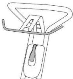
To engage the mower drive, simply push forward on the SP bail arm until it meets the handle grip. Releasing the pressure on the bail will de-clutch the drive mechanism. Naturally you may use the mower as a push model by gripping the handle in the normal way.
ADJUSTING DRIVE CONTROLS
Rotate the thumb wheel anticlockwise to increase clutch pressure.
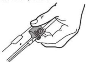

CAUTION
Adjust only to provide positive drive. Excess pressure will cause cable and belt stretch.
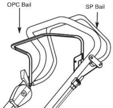
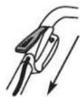
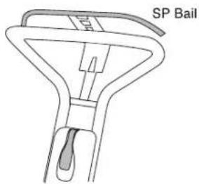
OPERATOR PRESENCE CONTROL (OPC) BAIL
This is a safety feature which stops the engine quickly if the operator releases their grip on the handle. To start the engine, you must move the bail back and hold it against the handlebar.

WARNING
If the machine run/brake mechanism is not adjusted correctly or is damaged the blade could continue to rotate after the OPC arm is released. In this situation, do not use the mower. Contact your local servicing specialist.
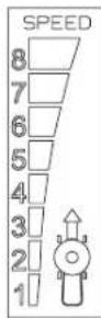
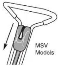
VARIABLE SPEED MODELS
Some models have an extra control mounted at the side of the handle to allow the travel speed of the mower to be varied without changing the engine speed. This control moves into any one of eight positions. Move the lever forward to increase travel speed and backward to lower it.
THIS LEVER SHOULD BE MOVED ONLY WHILE THE ENGINE IS RUNNING.
[If it is inadvertently moved back when the engine is stationary the drive belt will slacken and slip. To regain traction, move the lever forward with the drive disengaged and the engine running.]
Speed changes can be made whether the mower is moving or not.
THE GRASS CATCHER

CATCHER ASSEMBLY
There are three catcher types:
A. Bag Catcher
B. Moulded Plastic Catcher
C. Aero Catcher (moulded plastic top sections with fabric side panels.)
A. BAG CATCHER
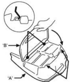
Slide the bag over the wire frame. Fit the 1. plastic clip up under the frame crossmember (the one which is formed into a handle) and hook the clip onto the wire crossmember. You may need a lever such as a screwdriver to open one end of the clip to get it started over the wire.
Pass the side and front clips inside the 2-frame and hook them onto the wire in a similar way.
Fasten the metal front lip to the catcher 3. assembly by bolting it to the plate on the bottom of the frame. The bottom panel of the catcher should be fitted between the plate and the lip as shown. Fit the screws from the top with the nuts under the lip, and tighten them securely.

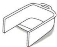
B. MOULDED PLASTIC CATCHER
There are two types. One has the top cover and handle already fitted to the top shell of the catcher, while the other requires these parts to be assembled.
If your catcher has these parts already assembled, start at step 4.
Place the top of the catcher shell (A) on a 1. firm level surface with its mesh upwards. Holding the top cover B with its concave 2. side facing the mesh, lift its rear end and engage the front clips with the hooks on the catcher top shell. Keeping them engaged, swing the rear of the cover downwards and press it down until the barbs on the cover engage with the slots in the shell.
Look for the "F" on the handle and ensure 3. that it will be adjacent to the "F" on the catcher shell. Fit the handle by pressing it firmly into the square recesses in the catcher top.
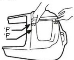
Turn the assembly over to confirm that the barbs on the handle are fully home, and push the tabs on the shell back into position to retain the handle.
Place the top shell on a solid work bench, 4. open side up. Don't use a table which may be damaged by scratching.
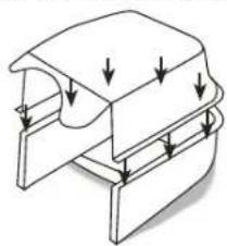
Position the bottom shell, upside down, 5.
over the top shell, carefully aligning the two parts and ensuring the barbed clips are aligned with their corresponding slots and squeeze the rear handles together.
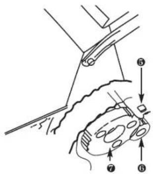
Keeping the catcher upside down, move 6. the assembly so the lip and rear handle is supported by the edge of the bench (see diagram) and catcher is trapped between your body and the bench.
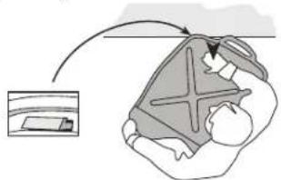
Strike the top of the assembly with an open 7. hand above the part supported by the bench. You should hear the barb click into place in its slot - if not, check the alignment and strike again with a little more force.
Working from left to right, and starting by 8. the rear handle, move around the catcher, supporting each fastener in turn on the edge of the bench, as it is pushed into engagement.
Finally inspect carefully to ensure that all 9. clips are fully engaged.
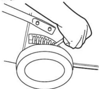
C. AERO CATCHER
With the top plastic moulding upside down, 1. fit the two ends of the wire frame, initially through the left-hand and right-hand loops of the bottom of the catcher, then into their anchor holes and swing the frame down to meet the top moulding. Fit two of the frame screws (the ones 2. nearest the top moulding) and tighten them snugly.
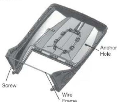
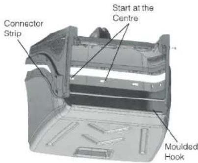
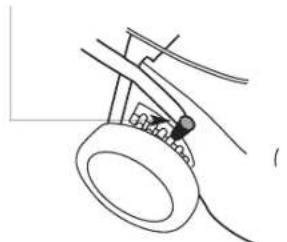
The moulded hook along the front edge 3. of the catcher bottom panel can now be clipped onto the horizontal part of the wire frame.
Swing the bottom panel into position, at the 4. same time pushing the connector strip into the slot in the top moulding. Start at the centre of the strip and work outwards until the strip is completely engaged. The slots in the strip should be aligned with the small barbs in the slot. Pull on the fabric of the catcher to make sure the strip cannot slip out of the slot.
Fit the two remaining screws into the wire 5. frame.
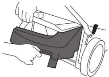
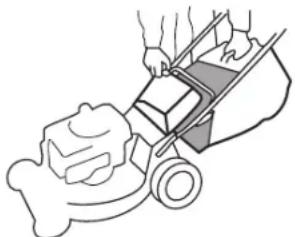
FITTING THE CATCHER

WARNING
THE CATCHER SHOULD BE FITTED TO AND REMOVED FROM THE MOWER ONLY WHEN THE ENGINE HAS STOPPED.
Standing to the right of the mower, reach down with your right hand and pull back and up on the handle of the safety flap or Smart Chute and lift it until it is parallel with the handle. Pick up the catcher with your left hand and swing it into position at the rear of the mower.
The catcher lip of the fabric and plastic catchers fits on top of the crossbar or the base of the tunnel, while the two hooks at the top of the Aero catcher mouth sit on top of the brackets inside the discharge outlet of the mower. The Series 18 Rotarola catcher has two lugs which fit on the hooks near the handle brackets of the mower.
Once the catcher is positioned correctly, lower the flap or Smart Chute to hold it in place. Make sure that the rear edge of the flap or Smart Chute is fully engaged on the lip or bar at the rear of the catcher mouth.
REMOVING THE GRASS CATCHER
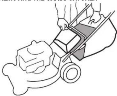

WARNING
ALWAYS WAIT UNTIL THE ENGINE AND BLADE HAVE STOPPED COMPLETELY BEFORE REMOVING THE CATCHER OR ADJUSTING THE MOWER. REMEMBER, THE MUFFLER AND NEARBY AREAS MAY BE VERY HOT.
-All models
Stop the engine and stand to the right of the mower. Grasp the catcher handle with the left hand and lift slightly while raising the safety flap or smart chute with the right hand. Lift the catcher clear and lower the flap or Smart Chute to cover the grass discharge outlet.

WARNING
Before clearing away any grass which may have lodged in the grass chute, ALWAYS STOP THE ENGINE, make sure the blade has stopped rotating, AND REMOVE THE SPARK PLUG WIRE.
EMPTYING
Dump the grass from the catcher by holding it vertical, using the rear handle of the moulded catcher or holding the rear end of the steel frame of the fabric catcher. Shake if necessary to dislodge a full load.
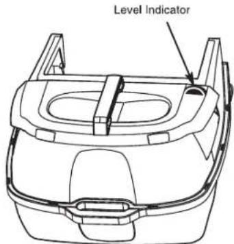
CATCHER LEVEL INDICATOR
Some grass catcher models have a Catcher Level Indicator to show how much grass has been collected. The indicator functions only when the engine is running at grass cutting speed. When the catcher is empty, the indicator will show all green, but as the grass progressively builds in height, a red indicator zone will appear and increase in size. Attempting to over-fill the catcher will result in discharge chute blockage or a "dribble" of grass from the front of the catcher.
Experience in your particular grass and cutting conditions will soon show the size of the red indicator area corresponding to the ideal catcher emptying point, Hose the catcher thoroughly after each use to keep the indicator movement free.
GRASS CATCHER MAINTENANCE
FABRIC TYPES. These depend on a free flow of air thought the fabric for effective grass collection. Wash as needed to restore an open mesh in the fabric. Do not leave a fabric bag in direct sunlight when not in use. While the bag will not rot if stored wet, prolonged sunlight exposure can cause premature breakdown of the material. Do not leave clippings in the catcher for extended periods.

WARNING
CHECK THE CATCHER BAG FREQUENTLY FOR DETERIORATION AND WEAR, AND REPLACE IF WORN. Use only genuine original equipment replacement catcher bags as others could be dangerous.
MOULDED PLASTIC TYPE. These also need a free passage of air for efficient catching. Keep the air outlet mesh clear by hosing it frequently. Do not leave clippings in the catcher.
CUT HEIGHT CONTROL
The single point cut height control adjusts all four wheels simultaneously. To operate, steady the mower by grasping the handle with one hand, pull the lever outwards from the mower with the other hand, and move it to the desired setting.
MOWING ACCESSORIES
A grass deflector chute of mowing without a catcher is available from your dealer. Not required for 'Smart Chute' models.
MOWING ADVICE
The best time time to mow your lawn is the early afternoon. By this time the grass has had a chance to dry out. Also the sensitive newly cut grass area isn't exposed to the direct sun.
For healthy growth, grass should not be cut too short. Using the lowest settings can result in destruction of the crown of grass, allowing flat lying weeds to develop.
Vary your cutting pattern from week to week. One week mow your lawn from north to south, the next week, mow your lawn from east to west. This will help prevent matting and graining of the grass.
For best performance, always keep the mower's blade sharp. A dull blade tends to tear, not cut, the blades of grass. When cutting very long grass, a preliminary cut on a high setting, followed by a lower cut (preferably a day or so later), will minimise the overall time required for the job.
Do not try to cut too much off the grass at one time. This can cause excessive loads to be put on the engine and also affect the mulching performance.
Avoid using the lowest two or three height settings when mulching. For best results when mulching; cut off only the top third (or less) of the grass. Cutting lower than this will have a detrimental effect on the mulching performance.
AVOID USING THE LOWEST
TWO OR THREE CUT SET
TINGS IN WET OR VERY
LONG GRASS
As you turn the mower at the end of a strip while mulching, you may notice unmulched grass. The mower deck is naturally tilted upward when turning so that the air flow which holds the grass in position for recutting is momentarily decreased. After mowing the lawn, you can go back and mow only the turns so that the clippings are no longer visible.
Clean the mowing chamber frequently to remove grass build-up. This will keep mowing performance at its best, especially when mulching. Avoid cutting your lawn when it is wet. Wet grass tends to form clumps and interferes with the mulching action of the mower.
If you are not collecting the cut grass, mow in a pattern that deposits the clippings on the previously cut swathe. So, if your mower discharges clippings on the left, the next cut should be to the right of the previous one, and vice-versa.
If you use the mower often without collecting the clippings, you will find that the accessory grass delivery chute (available from your Dealer for most models) will assist by spreading the clippings more effectively.

WARNING
DISCHARGE OPENINGS MUST BE GUARDED AT ALL TIMES. DO NOT REMOVE THE GRASS DEFLECTOR OR HOLD THE SAFETY FLAP UP WHILE MOWING.
When cutting close to obstructions such as tree trunks, and when mowing to the edge of a lawn where there is no wheel support, use the left side of the mower, giving a useful blade 'overhang' for ready access to awkward areas.
MOWING ADVICE—‘Smart Chute’
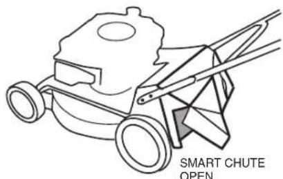
The 'Smart Chute' allows you to mow without catching the grass or mulching. By simply opening the door located on the bottom left hand corner of the Smart Chute, the lawn can safely be mown while smoothly spreading the clippings to the left. For wet, heavy or very long grass it is recommend setting the mower cut height to #4 or more to avoid the possibility of clogging. If clogging becomes persistent because of unfavourable conditions, try walking slower, cutting a narrower strip or raising the cut height more.


WARNING
Never use the 'Smart Chute' on the catcher with its door open. This could cause damage or injury to property or bystanders.
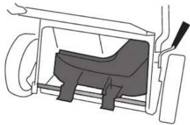
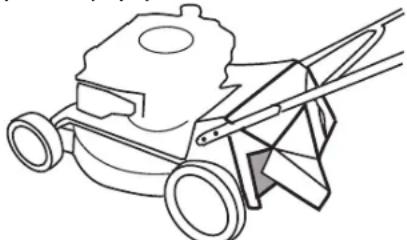
FITTING THE MULCHING BLOCK TO THE MOWER
Stop the engine1.
Make sure the discharge chute and the 2. underside of the mower are clean. See AFTER MOWING.
Raise the flap, and using the hand hold 3. on the mulching block, insert the mulching block, the angled section to the mower's right, into the discharge chute.
In the case of "open-back" mowers, make sure that the back of the block is sitting on the rear axle before lowering the flap. When fitting the block into a mower with a grass discharge chute, ensure that the lug at the left side of its base is slipped into the notch at the bottom rear of the chute sidewall before lowering the flap. See 'Mowing Advice' for mulching tips.

CHIPPER MOWERS

WARNING
Keep feet clear of the mower body when using the chipper tube.
When using the chipper tube place the mower on a level area where marking by rotating chippings won't matter. Before starting the mower fit
the catcher and set the cut height to its lowest setting. Check that the chipper feed tube is clear and the feed intake flap is in good order.

WARNING
Check frequently that the blade is sharp and the retaining screws are tight.
Branches up to 35mm can be chipped using the chipper tube. Only green timber should be chipped. DO NOT chip hard or dry wood. Hard and/or dry woods can be place unreasonable loading on the machine causing damage. Check that there are no nails or foreign objects in the material being chipped.

WARNING
Always stop the engine before attempting to clear any obstruction from under the mower or in the chipper tube.
Slowly feed material into the intake tube. Sturdy gloves, footwear, ear and eye protection should be worn. Empty the catcher frequently to avoid building up chippings inside the mower housing. Clear debris away from around the engine frequently to prevent any restriction with cooling air flow and prevent the risk of fire. Stop the engine before removing the catcher.
AFTER MOWING CLEANING

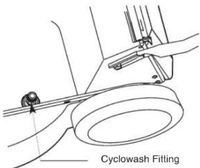
MODELS WITH A CYCLOWASH FITTING. Stop the engine and remove the catcher. Attach a garden hose fitting to the cylcowash fitting and start the engine. Allow a good flow of water to run for 2-3 minutes. Stop the engine and remove the hose. Hose the Catcher. MODELS WITHOUT A CYCLOWASH FITTING. Stop the engine and remove the catcher. Start the engine. Keeping well clear of mowing parts, apply a garden hose to the Wash port with a good flow of water for 2-3 minutes. Hose the catcher.
MODELS WITHOUT A CYCLOWASH PORT. Stop the engine, when the blade has stopped, disconnect the spark plug wire. Remove the catcher and tip the mower in accordance with the engine instruction book maintenance section (spark plug uppermost). Hose the underside of the mower clean. Hose the catcher.

CAUTION
DO NOT HOSE THE ENGINE, as water can damage the air cleaner and the ignition system. REFER TO ENGINE INSTRUCTION BOOK MAINTENANCE SECTION BEFORE TILTING MOWER. STORE YOUR MOWER ON ITS WHEELS, not its side.
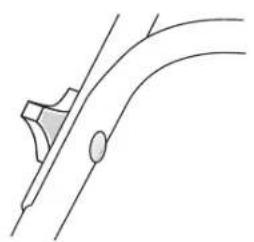
BLADES
DAMAGED BLADES AND WORN BOLTS ARE MAJOR HAZARDS.
Check the blade mounting bolts at frequent intervals for proper tightness.
Check the blade condition frequently, particularly if the mower has hit a foreign object or is vibrating. Sub-standard cutting and catching will result from a neglected blade. Your Authorised Dealer will be happy to sharpen or replace blades as necessary, or if you prefer, supply the parts you will need to do the job yourself.

CAUTION
ALWAYS USE GENUINE ORIGINAL EQUIPMENT PARTS TO ENSURE SAFETY AND PROPER PERFORMANCE. Substitute parts can be disappointing and dangerous.
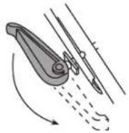
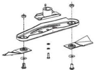
BLADE SERVICING INSTRUCTIONS. BAR AND DISC BLADES.
Remove the spark plug lead and position it 1. to prevent accidental contact with the spark plug.
Tilt the mower upright - refer to mainte-2. Nance section of the engine instruction book before tilting the mower. Keep the spark plug uppermost.
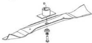
BAR BLADES. Remove the central bolt 3. and spring washer.
Remove the stepped washer and then the 4. blade. Either sharpen and balance the old blade, or fit a new one. Assemble in the reverse order, taking care to engage the stepped washer in the hole in the blade.
Follow steps 1 and 2 above. The cutting tips can be removed and replaced by removing the blade carrier from the mower. Note the component positions when dismantling. When refitting the blade carrier ensure the slots fit properly over the lugs and the drive plate, and replace the mounting bolts if they show signs of wear.
Quick Cut Blade
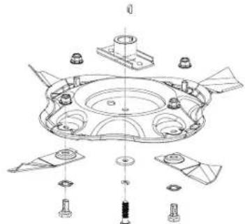
Quadcut Blade
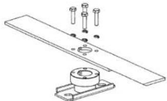
CHIPPER BLADE.
Follow the servicing instructions for 1. removing the "Bar and Disc Blades' on this page.
When the blade carrier is removed from the 2. crankshaft it can be placed in a vice and the chipper blade removed.
Either sharpen and balance out the old 3. blade, or fit a new one. The mower blade should also be inspected at the same time. Assemble in the reverse order, taking care 4. to align the keyway slot in the blade and the blade driver.
BLADE REPLACEMENT TORQUE SETTINGS:-
Blade centre bolt 45-50 Nm (33-37 ft.lb)
Four chipper blade 9-11 Nm (6.6 - 8 ft.lb) bolts
Tip mounting bolt 20 - 25 Nm (15 - 18 ft.lb)
ENGINE MAINTENANCE
Consult the engine booklet for the maker's instructions.
DRAINING THE OIL.
While most engines have a drain plug underneath them, it will be found more convenient to remove the oil dipstick and tip the mower on its side. Collect the old oil in a suitable tray such as a two litre ice cream container.
IGNITION.
Your engine has a breaker-less solid state ignition system which requires no maintenance other than occasional attention to the spark plug. We recommend cleaning an re-gapping every 50 hours with replacement every 100 hours (see engine instruction booklet).

CAUTION
DO NOT SANDBLAST PLUGS as abrasive grains can enter the engine and cause serious damage. USE ONLY THE EXACT TYPE OF REPLACEMENT PLUG specified in the engine instruction booklet.
AIR CLEANER.
A clean filter cartridge, correctly fitted, is ESSENTIAL for long engine life. Service the filter every 25 hours running (more often under adverse conditions) according to the instructions in the engine booklet.
MUFFLER.

A rusted or damaged muffler can permit increased exhaust noise. Check the muffler condition periodically and replace it only with a genuine original equipment part.
DRIVE MAINTENANCE
ROTAROLA.
Every 25 hours -
Remove the outer chain cover and apply grease to the chain.
Every 100 hours -
Remove the outer chain cover, disconnect the outer chain at its connecting link, withdraw the sprocket at the top end of the inner chain cover. Remove the inner chain cover and apply grease to the chain.
OTHER SELF PROPELLED MODELS.
Every 100 hours -
Remove each rear wheel by removing the hub cap, and undoing the 8mm nyloc nut and washer retaining the wheel to the axle. Remove the circclip retaining the pinion, taking care not to over stretch it, and remove the washer and pinion. Apply grease to pawl, pinion bore, and wheel gear Take care to replace the paws exactly as they were removed, and do not move pinions to the opposite side of the mower.
TROUBLE SHOOTING
| TROUBLE | PROBABLE CAUSE | SOLUTION |
| Uneven or poor cut. | Blunt blade. | Sharpen blade. |
| Heavy mulch left on cut strip. | Cutting height is too low for the height of the grass being cut. | Adjust the cutting height to remove approximately one third of the length of the grass. Then work down to the desired height. |
| Engine not running at full speed. | Move the throttle to fast. | |
| Underside of the mower's deck is clogged with wet grass clippings. | Hose off the underside of the mower. See AFTER MOWING. |
GEARBOX.
The gearbox on these models is a sealed unit that requires no maintenance. Just jeep the outside clean.
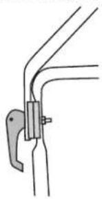
BELT ADJUSTMENT
SINGLE SPEED MODELS.
(Except self propelled Chipper models & Rotarola)
Keeping the spark plug uppermost, tilt the mower to gain access to the gearbox. Using two 10mm AF spanners, slacken the screw which clamps the gearbox anchor bracket to the mower housing just enough to allow the gearbox to be rotated about its output shaft. Rotate the gearbox to take any slack out of the V belt drive and re-clamp the anchor bracket in its new position by tightening the clamp and screw firmly.
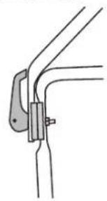
SELF PROPELLED CHIPPER MODELS AND ROTAROLA
These have a belt tensioning idler pulley. To adjust this, slacken off the clamp screw or nut which holds the V shaped idler pulley post and slide the post along the slot in the body. Retighten the screw or nut when the slack in the belt has been eliminated.
VARIABLE SPEED MODELS.
DO NOT tip the mower up as described above for single speed models. Variable speed models have an adjuster on the cable running down from the speed control to the drive mechanism. Alter this adjuster only if the travel of the speed control lever does not match the full range of available travel speeds.
The adjuster has three parts, two end fittings each attached to upper and lower outer cables, and a central barrel connected to the end fittings by right and left hand threads. Keeping the end fittings stationary, rotate the barrel to push the ends apart to increase travel speed, and to bring the end fittings together to reduce travel speed. Using this adjuster will compensate for belt stretch or wear which may occur.
INHOU
VERKLARING VAN DE SYMBOLEN 3
VEILIGHEIDSINSTRUCTIES 13
DE MAAIER MONTEREN 14
DE MOTOR VOORBEREIDEN 14
DE MOTOR BEDIEN 15
STARTEN 15
STOPPEN 16
BEDIENINGSHENDELS 16
DE GRASOPVANGBAK 16
MAAIADVIES 18
HET MULCH-BLOK 19
MAAIERS MET HAKSELAAR 19
NA HET MAAIEN 19
MESSEN 19
ONDERHOUD 20
STORINGLABEL 20
DEZE HANDLEIDING OMVAT EEN REEKS VERSCHILLLENDE MAAIERS. HET KAN ZIJN DAT SOMMIGE ONDERDELEN ERVAN NIET VOOR UW MAAIER GELDEN.
QUICK CUT-MES/QUADCUT-MES.
BLADE REPLACEMENT TORQUE SETTINGS:-
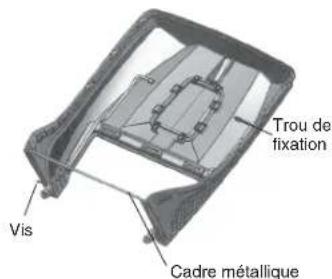
- With the top plastic moulding upside down, fit the two ends of the wire frame, initially through the left-hand and right-hand loops of the bottom of the catcher, then into their anchor holes and swing the frame down to meet the top moulding.
- Fit two of the frame screws (the ones nearest the top moulding) and tighten them snugly.
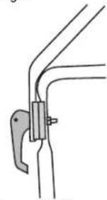
Sperposition for Transport.
Quick Cut Messer/Quadcut Messer.
A Anything to be done or done with the manubrio is a quella inferiori.

ACTALENZONE
There are three catcher types:
REMOVING THE GRASS CATCHER

-Tutti i modelli

EXAMARILSUNTLZEOIDVEEST
OTHER SELF PROPELLED MODELS.
Ogni 100 ore
137 Mt Wellington Highway. Panmure,
P.O.Box 14349 Auckland 1060.
INDICE
There are three catcher types:

"SMART CHUTTE," CERRADA EN EL RECOGEDOR DE CESPED

ADVERTENCIA
INSTRUÇOES DE MANUTENÇA DA LÁMINA.
LÁMINAS DE BARRA E DISCO.
Retire o cabo da vela e posizione-o de 1. modo a impeder o contacto acidental com a vela.
(Except self propelled Chipper models & Rotarola)
WYLOT SMART CHUTE OTWARTY


OSTRZEŽENIE
B. STOPT PLASTOPPSAMLER
MONTEREREOPPSAMLEREN

ADVARSEL
OPPSAMLEREN SKAL VERE MONTERT OG FJERNES BARE NAR MOTOREN HAR STOPPET
Stä til hóyre for gressklipperen, bruk hóyre hand og dra handtaket på sikkerhetsklaffen er Smart Chute tilbake og opp og lott det til det er parallelt med handtaket. Locht opp fangeren med venstre hand og sving den i posisjon bak på gressklipperen.
Fangerleppen pa stoffet og plastopsamlerne monteres overst pa tverrstangen erller basen til tunellen, mens de to krokene overst pa Aerofangerapningen er plassert pa braketter innate i utkastersapningen pa gressklipperen. Serien 18 Rotarola-fanger har to orer som passer pa krokene som star naer brakettene pa handtakenie til gressklipperen.
Nár fangeren er korrekt plassert, skal du senke flapsen er Smart Chute sik at den holdes pa plass. Kontroller at bakkanten pa flapsen er Smart Chute er helt i inngrep med leppen er stangen bak pa fangerapningen.
FJERNE GRESSFANGEREN

ADVARSEL
VENT ALLTID TIL MOTOREN OG BLADET HAR STOPPET HELT FDR DU FJERNER FANGEREN ELLER JUSTERE KILLPEREN. HUSK AT EK-SOSPOTEN OG NÆLIGGENDE OMRÄDER KAN BLI VELDIG VARMT.
-Alle modeller
VEDLIKEHOLD AV GRESSFANGEREN
VEDLIKEHOLD AV DRIVET
ROTAROLA.
Hver 25. time -