BC 260 SST - Lawn mower Morrison - Free user manual and instructions
Find the device manual for free BC 260 SST Morrison in PDF.

| Product Type | Lawn Mower |
| Brand | Morrison |
| Model | BC 260 SST |
| Power Source | Petrol (4-stroke) |
| Engine Displacement | 260 cc |
| Cutting Width | 53 cm (21 inches) |
| Cutting Height Adjustment | 6 positions, 25-75 mm |
| Grass Collection Bag Capacity | 70 liters |
| Weight | 35 kg |
| Dimensions (L x W x H) | 143 x 53 x 105 cm |
| Fuel Tank Capacity | 1.5 liters |
| Cutting Deck Material | Steel |
| Drive Type | Self-propelled, variable speed |
| Handle | Folding for compact storage |
| Safety Features | Blade brake, operator presence control |
| Maintenance | Oil change every 25 hours, air filter cleaning |
| Warranty | 2 years |
| Mulching Capability | Yes (mulching plug included) |
| Side Discharge | Available as accessory |
| Noise Level | 96 dB(A) |
Frequently Asked Questions - BC 260 SST Morrison
User questions about BC 260 SST Morrison
0 question about this device. Answer the ones you know or ask your own.
Ask a new question about this device
Download the instructions for your Lawn mower in PDF format for free! Find your manual BC 260 SST - Morrison and take your electronic device back in hand. On this page are published all the documents necessary for the use of your device. BC 260 SST by Morrison.
USER MANUAL BC 260 SST Morrison
natural_image
Industrial machine with red and white components, no visible text or symbolsOwner's Manual
Important
Please read these instructions carefully before assembly, to reduce risk of fire, burn hazard or other injury. Keep these instructions in a safe place for future use.
This manual covers the Morrison BC 260 SST, BC 260E SST Combination Unit and attachments. Includes engines 1E34F and 1E34F-2E
| Sections |
| Brancutter 2 |
| Hedge Trimmer 18 |
| Pruning Saw 50 |
| Eoger 44 |
| Cultivator 52 |
Contents
| Meaning of oedograins 2 | |
| Technical Data 3 | |
| Names of Parts 4 | |
| Safety Instructions | 5 |
| Ensuing Safe Operation | 6 |
| Fuel and Oil | 8 |
| Assembly | 8 |
| Starting and Stopping the Engine | 10 |
| Wearing the Harness | 11 |
| Inspection and Maintenance | 13 |
| Long-term Storage | 15 |
| Troubleshooting | 15 |
About This Manual
Thank you for purchasing this product. The instruction manual describes operating procedures and precautions as well as inspection and maintenance procedures for the machine. Before using this device, read this manual carefully until you are familiar with the contents. Carefully observe all warnings and safety instructions to ensure correct operation of the machine. Doing so will ensure safe operation and optimum performance of the device. This instruction manual covers the attachments, controls, and engine of the Multi-Combination System. Use only attachments specified by the manufacturer. Use of any other attachment can result in damage to the equipment, possibly leading to death or severe injury. Be sure to strictly observe the important safety information that follows each bulleted term below. Failure to follow the instructions for correct operation contained herein can result in a severe accident.
DANGER: Indicates that failure to follow the instructions creates an imminent hazard leading to death or severe injury.
WARNING: indicates that failure to follow the instructions has the potential to result in death or severe injury.
CAUTION: Indicates that failure to follow the instructions can lead to minor injury or severe damage to the machine.
NOTE This is an auxiliary explanation that provides useful information and instructions.
Meaning of Pictographs
| DANGER WARNING CAUTION | |
| Never attempt to mount a saw blade on this brushcutor. | |
| Do not operate the device within 15meters of a child, animal, or bystander. | |
| Wear safety gear.1. Race shed or protective goggles2. Head protection3. Ear protection4. Heavy-duty gloves5. Non-trip safety shoes | |
| Before using this device, read the manual carfully until you are familiar with the contents. | |
| Do not ravel or operate the machine near open lamp. | |
| Watch out for objects thrown from the brushcutor. | |
| Do not run the engine in a room or in any confined area where exhaust emissions can accumulate. | |
| Never touch the spark plug cap or high-voltage wire while the device is running. | |
| Do not touch metal parts that can become very hot during and immediately after device operation. | |
| Waste electrical products should not be disposed of with household waste. Possible recycling where facilities exist. | |
| Warning! Never mostly a trimmer or cutter in any way. Improper use of any trimmer can cause Serious or Fatal Personal injury. | |
| Always Turn Or Engine and make sure the cutting tool has stopped before cleaning, removing or adjusting blades. |
Technical Data - Brushcutter
| Model | CG 260AF/BC 260 SST | CG260AF E/BC 260E SST | ||
| Mases | Unit without cutting attachment, empty tank | 4.04kg | 5.9kg | |
| Line Trimmer & Nylon Head | 1.72kg | 1.72kg | ||
| Cutting Attachment | Nylon Trimmer | Nylon line diameter | 2.5mm | 2.5mm |
| Blade | Specified blade diameter | 255mm | 255mm | |
| Specified blade thickness | 1.4mm | 1.4mm | ||
| Number of cutting teeth | 3 | 3 | ||
| Confor hole diameter | 25.4mm | 25.4mm | ||
| Rotational speed at maximum allowed engine speed | 8000 min-1 | 9500 min-1 | ||
| Type of handicap | D' grip | 'D' grip | ||
| Gear Ratio | 1:22 | 17:22 | ||
| Rotational direction of output shaft | Seen from above: anticlockwise | Seen from above: anticlockwise | ||
| External dimensions | Length of main unit | 1000mm 1000mm | ||
| Length of drive shaft section to drive head | 700mm | 700mm | ||
| Engine | Name of Engine | 1E34F | 1E34F-2E (EU V) | |
| Type | Air cooled; 2 cycle; vertical piston valve; petrol engine | Air cooled; 2 cycle; vertical piston valve; petrol engine | ||
| Dry Weight (kg) | 3.2 | 3.1 | ||
| Engine displacement | 25.4cm2 | 25.4cm2 | ||
| Maximum output (kW/mn) | ≥ 0.75/7500 | ≥ 0.70/7500 | ||
| Carburetor | Diaphragm type | Diaphragm type | ||
| Ignition | Non-contact electronic ignition | Non-contact electronic ignition | ||
| Method of Starting | Recoll type | Recoll type | ||
| Fuel used | Good quality 91 octane gasoline with quality proven motor oil for air cooled 2 cycle engines ratio 25:1) | Gasolina mixed with ioncating oil (ratio of 30:1) | ||
| Volume | Fuel Tank | 0.75 L | 0.85 L | |
| Rotational speeds | Engine speed at maximum power | 9000 min-1 | 10000 min-1 | |
| Recommended maximum engine speed | 8000 min-1 | 7800 min-1 | ||
| Output shaft speed | 7500 min-1 | 7500 min-1 | ||
| Recommended engine claring speed | 2500 min-1 | 2800 min-1 | ||
| Sound pressure levels1) | Racing (Lsp) | < 102 dB | < 102 dB | |
| Sound power levels2) | Racing (Lx) | ≤ 120 dB | ≤ 120 dB | |
| Vibration levels3) | Racing (FvL) | ≤ 15 m/s2 | ≤ 15 m/s2 | |
1; Reference for harmonized standard: ISO 22968 2; Reference for harmonized standard: ISO 22968 3; Reference for harmonized standard: ISO 22967
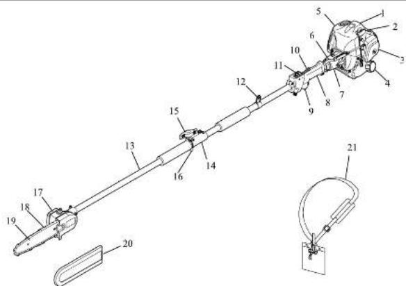
Names of Parts (with solid blade attached)
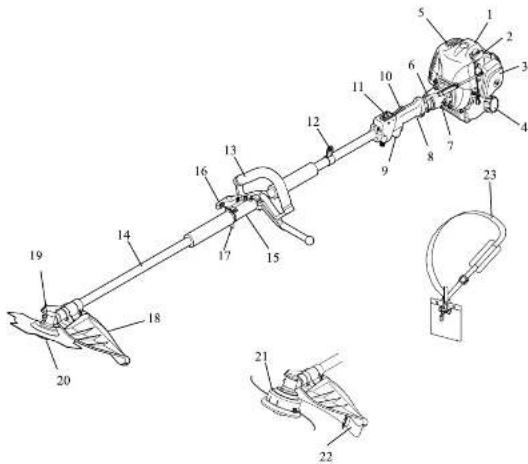
- Engine
- Spark plug
- Air cleaner
- Fuel tank cap
- Mufler
- Throttle Inkappa
- Clutch case
- Control handle
- Throttle trigger
- Throttle bripper, pokaol
- Stop switch
- Suspension point
- Loop handle
- Shaft tube
- Cancelat
- Kreb
- Bng Pul
- Cutto attachment guard
- Angle transmission
- Blade
- Nylon trimmer
- Skirt
- Нетеза
Safety Instructions
- About This Manual
CAUTION

Fig.2-1
This manual contains important safety instructions. Before using the device, read this manual carefully until you are familiar with the contents. Carefully observe all warnings and safety instructions to ensure correct operation of the machine. Doing so will ensure safe operation and optimum performance of the device.
CAUTION
This instruction manual does not cover all possible situations and conditions. Although we have taken all possible steps to ensure the safety of this device, the operator and the person performing maintenance of the device must also take all possible steps to ensure safety.
- Recommended Uses
△CAUTION
Use this brushcutter only to cut weeds or brush below your knee height. Do not use it for delimong, bucking or felling of trees.
- Safe Practices
△CAUTION
Follow local noise regulations regarding the acceptable times and locations for using this device. Also observe current local safety regulations, standards, and ordinances.
- Replacement Parts
WARNING
To maintain optimal safety and performance, use only the manufacturer's genuine parts and accessories. Do not modify the device or use it for purposes other than those specified. Failure to observe this requirement can result in severe accidents and damage to the device.
- Never use a saw blade.
CAUTION

Fig.2-2
Never attempt to mount a saw blade on this brushcutter; it is not designed to use a saw blade. The cutting attachment guard, loop handle or harness for this device does not meet the safety standard for a saw blade.
- Operator Safety
WARNING
Do not operate this device if you.
• cannot concentrate due to fatigue, illness, or injury;
• are under the influence of drugs or alcohol
• are under the age of 15;
• are pregnant.
If any of the above applies, a possible lack of judgment can result in an accident.
- Monitor the weather
WARNING

[Non-Text]
Fig.2-3
Do not operate the machine under any of the following circumstances:
- When the ground is slippery or you cannot maintain a stable posture for any reason.
- At night, in heavy fog, or at any other times where your field of vision is limited and it is difficult to gain a clear view of the working area.
- During rainstorms, thunderstorms, in strong or geiaforce winds, or in any other adverse weather in which use of this device would be unsafe
- Using Safety Gear
WARNING

Fig.24
Always wear proper clothing when using this device.
- Tight-fitting, sale, and non-restricting clothing including a long-sleeved shirt and a pair of trousers. (Avoid wearing shorts or baggy clothing.)
- Loose-fitting clothing can become entangled in a tree branch or the like, posing the risk of tripping and resultant injury.
• Ear protection to protect your hearing
- Face shield or protective goggles
• Heavy-duty gloves
- Non-slip safety shoes (Never operate this device while barefoot or when wearing sandals.)
- Head protection to protect your head from thrown objects, etc.
- Basic Operations
CAUTION
- To ensure safe operation of this device, become familiar with the safety instructions and the procedure for shutting off the engine. (See Starting and Stopping the Engine.)
- In an emergency, it may be necessary to quickly release the machine from your body, therefore, familiarize yourself with the correct use of the harness quick release mechanism. (See Wearing the Harness • Quick release mechanism.)
- Cutting Attachment Guard
WARNING
Never operate the brush cutter without the cutting attachment guard properly installed. (See Mounting the cutting attachment guard.)
The cutting attachment guard protects the operator from thrown objects and prevents the cutting attachment from contacting the operator. If the cutting attachment is not properly installed, a thrown rock can cause death or severe injury.
11. Fuel Handling Precautions
DANGER
- Do not operate the machine near open flame or spilled fuel.
- Do not refuel while the engine is running or while the engine is
still hot after shutting off the machine,
• Do not refuel while smoking.
• Thoroughly wipe away any soiled fuel after refueling.
- Start the engine at a location at least 3 meters away from the refusing area or the fuel container. Fuel is highly inflammable, and a fire can lead to death or severe injury.
12. Exhaust Gas Precautions
DANGER

Fig.2-6
Do not run the engine in a room or in any confined area where exhaust emissions can accumulate. Doing so can result in an accumulation of carbon monoxide and other poisonous gases that can cause death or severe poisoning.
13. Cutting Blade Precautions
DANGER
- Do not approach the running blade or nylon trimmer with your hand or foot.
- If long grass or any other object becomes entangled in the cutting blade or nylon trimmer, shut off the engine and wait for the cutting blade or oven trimmer to stop completely.
- Wear heavy-duty gloves and use caution when handling the stopped blade. The cutting blade is very sharp and can cause death or severe injury.
14. The Hazard Area
WARNING

Fig.2-7
- Do not operate the device within 15 meters of a child, animal, or bystander. Consider a 15-meter radius around the device to
be a "hazard area."
- If someone approaches the hazard area, immediately shut off the engine. A running machine can eject debris or gravel at a speed that can cause death or severe injury.
15. Limit your worktime
WARNING
- Do not operate the machine for more than 2 hours a day. - Rest for 10 to 20 minutes after every 30 to 40 minutes of operation.
Continuing to operate the brush cutting without a break can result in excessive fatigue. The resulting loss of attentiveness can lead to an accident or problems with your fingers or hands. If you experience any abnormal symptoms such as pain, discomfort, or paralysis of the fingers or hand, immediately stop operating the machine and seek medical attention.
18. Avoiding Electric Shock

Fig.2-8
Never touch the spark plug cap or high voltage wire while the device is running. Doing so can result in a high voltage electric shock that can cause death or severe injury.
17. Avoiding Burns
CAUTION

Fig.2-9
Never touch the muffler, muffler cover, exhaust pipe, cylinder or cylinder head while the machine is running or immediately after operation, as they become very hot. Doing so can cause burns.
Ensuring Safe Operation
A CAUTION
To ensure safety, strictly observe the following instructions. Failure to do so can lead to persons' injury or severe damage to the machine.
1. Uses of the cutting blade and nylon trimmer

The oruscutter can be used with either the cutting blade or nylon trimmer.
Black
The cutting blade can be used to cut various types of grass.
Naten Lommer
The nylon trimmer is suitable for lawn-mowing or brushcutting in locations with obstacles such as trees, fences or walls.
NOTE
When operating the brushout, install the appropriate cutting attachment guard being used. (See Fig 1 & 2 Mounting the cutting attachment guard.)
2. Pre-operation inspection
Carefully inspect and perform any necessary maintenance before starting the machine. Failure to do so can lead to severe property damage or damage to the machine.
a. Tighton or replace loose or lost screws. Confirm that the cutting blade or nylon trimmer has been fully tightened.
b. Replace any damaged or worn parts.
c. Check for soiled fuel. Check the fuel tank cap and wipe of any spilled fuel. Check the cutting blade or nylon trimmer for chipping, cracks, deformation or excessive wear.
For more information, see inspection and maintenance.
3. Marking the hazard area
A circular area within a radius of 15 meters of the machine is the hazard area. When necessary, mark the area with yellow warning rope and post a warning sign.
4. Removing obstacles from the work area
Before starting operation, remove any rocks, pieces of rope, metal strips, and other obstacles that can become entangled with rotating parts of the machine from the work area. Mark any hard stationary objects so that the operator can avoid them.
5. Holding the brushcutter

natural_image
Line drawing of a person using a long pole to measure a small object, labeled Fig.3-2 (no text or symbols on the diagram itself)NOTE
See Section Wearing the Harness
- Hold the brushcutter on the right side of your body.
- Before starting the engine, put on the harness correctly, attach the brushcutter to the harness, and stand in the correct brushcutter holding stance.
6. Starting the engine
NOTE
See Section Starting and Stopping the Engine
- In some cases the cutting blade or nylon trimmer can suddenly begin rotating when the engine is started. Provide a safe distance around the cutting blade or nylon trimmer before starting the engine.
- Make sure that no bystanders are within 15 meters before starting the engine.
- Place the machine on flat solid ground before starting the
engine.
- Make sure the cutting blade or nylon trimmer is not in contact with the ground or any other object.
- Ensure the blade is securely lightened before use.
7. Safety Precautions
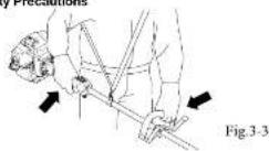
- Hold the machine securely with both hands. Grip the control handle with your right hand; grip the other handle with your left hand.
• To maintain a stable posture, adopt a stance wider than - shoulder width.
- Maintain a firm footing.
- Shut off the engine if abnormal noise or vibration occurs, if an emergency causes, or when rutting down the machine.
-
If someone calls out or otherwise interrupts you while working, always shut off the engine before turning around.
-
Special precautions when two or more machines are in use. When two or more machines are in use simultaneously, it is essential that all operators use extreme care to maintain a safe distance from each other, constantly look around, and always remain aware of presence of the other operators to ensure safe operation.
9. Blade thrust
It a running blade hits a hard stationary object such as a tree, rock, or well, the cutting blade can kick back violently in a phenomenon known as blade thrust. When blade thrust occurs, the reaction can swing the cutting blade velocity in an unexpected direction, creating a high risk of injury. To avoid blade thrust, strictly observe the tailwane:
- Before starting work, check for hard stationary objects such as trees, rocks, or walls that can cause blade thrust. Mark any hard stationary objects so that the operator can avoid them.
- Do not use an excessively dull cutting blade.
10. Cutting pattern

Fig.3-4
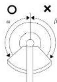
Fig.3-5
Place
- The cutting attachments of the brushcutter rotate counterclockwise. Cut a 1.5-meter arc from right to left. Within this arc, maintain the cutting blade at a consistent height above the ground. Advance slowly and gradually, beginning with the right foot.
- Cut brush with the arc a on the cutting blade. If the arc on the rotating blade hits a solid object, a cutting blade running at high speed will thrust toward the operator, creating a very dangerous situation. If Fig.3-5:
11. Abnormal noise and vibration
- If the machine suddenly exhibits abnormal noise or vibration, immediately shut off the engine.
- Possible causes of sudden noise or vibration include loose screws and damage to the cutting blade or other components. Check the entire machine for any sign of a problem.
• After the cause has been found, do not use the machine until you have completed the repair.
Fuel and Oil
DANGER
- Do not handle fuel near open fire (open flame, lit cigarette, stove, etc.) or electrical spark (from electrostatic discharge, welding spark, or switch or battery short-circuit). Doing so can cause the fuel to ignite, resulting in a fire.
- Do not refusal while the engine is running or while the engine is still hot after shutting off the machine. Allowing fuel to splash on a hot engine can result in a fire.
- Refuel the machine outdoors or in a well-ventilated location. - After refueling, security close the fuel cap and thoroughly wipe off any soiled fuel. Spilled fuel can ignite alter the machine is running, leading to a tre.
NOTICE
Refer to the engine instruction manual for more details,
2-stroke engine

natural_image
Technical line drawing of a mechanical component with no visible text or symbolsFuel
When fueling a 2-stroke engine, use a fuel-cl mixture of gasoline and 2-stroke engine cl.
- When mixing gasoline with two-cycle engine oil, use only gasoline which contains NO ETHANOL or METHANOL (types of alcohol). Use branded 3" octane or higher unsealed gasoline known to be of good quality. This will help avoid possible damage to the engine fuel lines and other engine parts.
• 2-stroke engine oil required Use high-quality JASO FC class 2-stroke engine oil.
NOTICE
Pour the engine oil into a mixing vessel. And gasoline
AND THIS THORCHY.
- Do not mix the engine oil and fuel in the fuel tank of the engine. - Fuel-oil mixtures degrade over time. We recommend that you prepare only the amount of the fuel-oil mixture you will use in the short term. Do not use a fuel-oil mixture that was prepared more than a week earlier. A degraded fuel-oil mixture can damage the engine.
- Do not use a fuel-oil mixture containing an incorrect proportion of engine oil. Doing so can cause an engine malfunction or engine seizure.
When using a mineral oil
Mix Ratio 25:1 Gasoline litres: 1 2 3 4 5 2 cycle oil mL: 40 80 120 160 200
When using a semi-synthetic mineral oil:
Mix ratio 40:1 Gasoline Illinois: 1 2 3 4 5 2 cycle oil mL: 25:50 /5 100 125
IMPORTANT
Two-stroke fuel may operate. Shake the fuel container thoroughly before each use. Stored fuel ages. Do not mix more fuel than you expect to use within a month.
Assembly
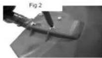
Installation of the guard
Place the brush cutter with the head tacing up.
Line up the 4 screw holes in the guard with the bracket (Fig 1) on the shaft.
Insert 4 screws through the guard into the captive nuts in the bracket (Fig2) and tighten.
Fig 1

WARNING
The black fitted to the guard is sharp and can cause injury, always wear gloves
Installation of the nylon head
- Lay the brush cutter on its back with the gear box sham facing
- Insert the Allen key onto the hole in the gear box cover.
- Rotate the gear box shaft until the Allen key slices into the blade holder (Fig. 3).
- Screw the nylon head anti-clockwise (turn left) onto the threaded shaft at the end of the gear box.
- Make sure that the nylon head is securely locked in position.
- Remove the Allen key.

Remove Allen Key

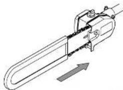
Installation of the 3 tooth blade
Always wear gloves when touching the blade
- Lay the brush cutter on its back with the gear box shaft facing up, insert the Allen key into the hole in the near box row.
- Rotate the gear box shaft until the Allen key slices into the blade holder (Fig 4).
- Place the 3 tooth blade on the upper blade holder, centing the blade on the raised centre (Fig 5).


Fig.6
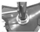
Fig 7
- Fit the lower blade holder (Fig 5) and washer.
- Screw the nut anti-clockwise (turn left) and tighten using the spanner provided (Fig 7).
- Make sure that the blade is completely and safely locked in position, and there is no space between the blade and the blade holder.
- Fit split pin [fig 8].
- Remove the Allen key.

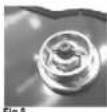
The blade MUST be correctly positioned on the upper blade clamp otherwise SERIOUS DAMAGE AND INJURY TO PERSONS AND PROPERTY could result.
Fitting the handle
Fix the loop-hands to the shaft over the rubber block provided (1 Fig 9) Adjust to a comfortable working position then tighten the fixing screws securely (Fig. 10).


Replacing the nylon cord
Check thoroughly if the nylon head is worn out before replacing the cord. If you can see serious traces of wear, you must replace the complete nylon head.
- Stop the engine
- Open the nylon head by pushing on the catch (Fig 11) and twisting the cover anti-clock wise
- Pull the bobbin out of the nylon head and take out the rest of the nylon cords.
- Cut the cords, 2.4mm Ø and 5 meters long in two equal lengths.
a. Make a loop folded at each end of the two nylon cords and insert those in the two holes provided for on the bobbin (Fg12) and wind it clockwise maintaining an even and firm tension onto the bobbin, being careful not to twist the line. - After winding the cord, insert both ends into the notches on the bobbin (Fig 13t).
- Introduce each end of the cords in the holes provided (Fig 14).
the cords should stick out 15 cm each side.
- Pull the cords to free them from the notches, refill the spool cover.
Never use cutting device other than those supplied by the manufacturer.
(Steel cord is never allowed).
Always use original spare parts in order to benefit from continuous warranty.

Fig 11 Catch

Fig 12

Fig 13

Fig 14
Attaching The Tools To The Drive Shaft Assembly
- Host the power unit/shall assembly on a flat firm surface.
- Ensure that the clamping wing nut (2) is loose, pull out lock pin (1).
- Carefully at attachment drive shaft assembly (5) into coupler (3).
- After the attachment drive shaft is in the coupler, release the locator pin (1).
- Turn the attachment drive shaft until the locator on engages with the locating hole (4) in the drive shaft, when this has happened it will not be possible to twist the drive shaft.
- Secure the drive shaft by tightening the clamping wing nut (7).


Transportation
- Never transport the multi-tool with the engine running. An engine that's running could be accidentally accelerated causing the attachment to operate.
- When carrying by hand, the engine should be pointing forward.

Starting and Stopping the Engine
Starting the Engine
CAUTION
Do not pull the starter cord all the way out and do not let go of the starter handle when the cord is extended, this can damage the starter mechanism.
Before starting the engine, inspect the entire unit for loose fittings or fuel leaks, and verify that the cutting attachment is properly installed and securely fisatened.
Pace the unit on a flat, firm pace. Keep
the curing head cost of any obstructions
check that there is been in the bank
and that the fuel cap is screwed on
山Car
(2) Fuel tank
- When starting a cold engine move the choke lever (behind the air cleaner cover) to the closed position. (1) Choke lever (2) Closed (3) Open

Diagram.A

Diagram .B
- If the engine has been running and is still warm, move the choke lever to the open position.
- Press the priming bulb under the carburettor repeatedly until excess fuel can be seen returning to the tank through the clear fuel return pipe.
- Slide the ignition switch (2) on the trigger grip away from the STOP position (See Diagram .C on the next column).
- To set the throttle in the start position.
- Degress the safety lever (1)
- Squeezs the throttle lever (1) fully. Hold down the starting button (3) while releasing the throttle lever.
- The throttle lever will be held partly open until it is squeezed again.
(1) Throttle lever
(2) Ignition Switch
(3) Starting Currion

- While holding the unit firmly, pull out the
starter rope quickly. - After the engine has started, open the
- Allow the engine to run for 2 to 3 minutes to warm up before starting work.
NOTE
Overchoking
- Should the engine become flooded due to over-shocking set the ignition switch to the STOP (O) position Fig. 35, unscrew the spark plug, wipe it dry or replace, pull the recoil starter several times without the spark plug in place and with the choke in the open position. This will help clean and ventilate the combustion chamber.
STOPPING THE ENGINE
- Set the engine to cling by releasing the throttle lever.
- Set the ignition switch to the STOP (O) position.
- If the engine fails to stop, set the choke lever to the closed position to stall the engine; do not use the machine until the ignition switch is repaired.
RUNNING IN
- During the first ten hours of work, avoid running the engine at maximum speed for a prolonged period until all the components have bedded in. After the engine has been run-in, it will reach its maximum power.
Wearing the Harness
The harness has a quick-release mechanism that allows you to immediately release the machine from the harness in an emergency.
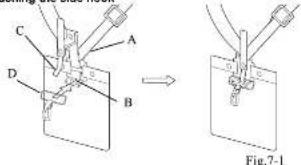
Attaching the side hook
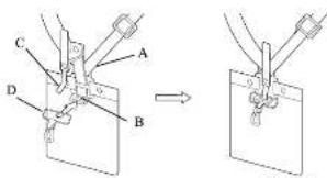
Fig.7-1
NOTE
If side hook (D) has disengaged from hook (B), engage it.
1. insert hook [Bi] into side Rock [D].
2. While holding hook (B) and side hook (D) in place, insert slupper (C) into the hole on hook (B).
Adjusting the harness

Fig.7-2
1. As shown in the diagram, adjust the harness (A) so that hip pad (I) is against your right hip. (Fig.7-2)
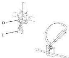
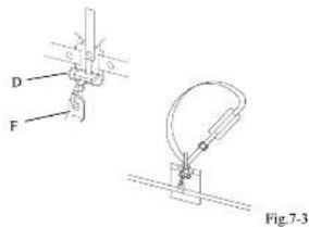
Fig.7-3
2. Before starting to work, attach the side hook (D) to the suspension point (F) on the shaft tube. (Fig.7-3)
Recommended working position
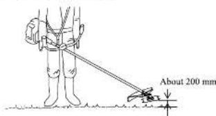
Fig.7-4
CAUTION
If releasing both hands from the handle, use extreme care. Suddenly
releasing the handle can cause the cutting blade or nylon trimmer to kick, possibly resurring in injury.
- Before starting the engine, put on the harness correctly, attach the brushcutter to the harness, and stand in the correct brushcutter holding stance.
- Ensure the cutting blade is 100 mm to 300 mm above the ground before releasing both hands from the handle.
- Ensure the nylon trimmer is 0 mm to 300 mm above the ground before releasing both hands from the handle.
- See "Adjusting the holding position" for details.
NOTICE
After installing a new cutting attachment, confirm the correct holding position and make any necessary adjustments.
Adjusting the holding position
- To adjust the holding position, simply change the length of the harness belt and the location of the suspension point.
- Use the following procedure to adjust the suspension point.
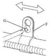
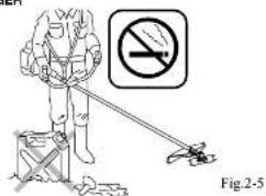
Fig.7-5
CAUTION
- To find the optimal brushoutter holding position, change the location of the suspension point gradually in increments of 5 to 10 mm. Moving the suspension point too far in one stop can cause you to lose your balance when checking the new brushoutter holding position, possibly leading to tripping and injury.
- Always fully tighten the screw & washer assembly (C) IV6 x 12 before checking the brushcutter holding position. Otherwise, the brushcutter can change position suddenly while you are checking the brushcutter holding position, causing you to lose balance and possibly leading to tripping and injury.
- Loose the screw & washer assembly (G) (M8 x 12).
-
Adjust the location of suspension point (E).
-
Fully tighten the screw & washer assembly (GI) (M6 × 12).
Quick-release mechanism
WARNING
- In an emergency, releases the throttle trigger and shut off the engine. Support the machine with your left hand and operate the quick-release mechanism. Be aware that the machine will fail and that a rotating blade or nylon trimmer can cause death or severe injury.
- Be careful not to accidentally operate the red belt (H) on the harness. Be aware that the machine will fall and that a rotating blade or nylon trimmer can cause death or severe injury.
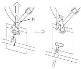
Fig.7-6
In an emergency, pull upward on the red belt (H) on the harness. This quickly releases the machine from the harness.
NOTICE
Before using the machine, check that the quick release mechanism is functioning.
Inspection and Maintenance
IMPORTANT
After every use, check that all nuts, bolls and screws are securely fastened and tighten if necessary.
Fuel Filter
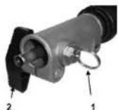
Every 15 hours of operation, using a wire hook, take the fuel filter from the fuel tank Fig 36 and clean or replace with a new fuel filter.
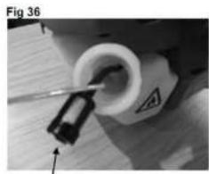
natural_image
Close-up of a mechanical component with a tool inserted, showing a circular opening and a warning symbol (no readable text or symbols)fuel filter
Fig 37
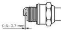
Spark Plug
- Poor starting or misfiring is often caused by a fouled or defective spark plug, clean and reset the gap to 0.65 mm, or replace the spark plug with NCK: BPMR7A as necessary Fig S7.
Air Filter
- Before using the multi-tool, check the air filter Fig 39. Being clogged will reduce the engine performance.
- Remove the air filter cover by undoing the cover screw Fg 38, clean the filter element in warm, scaby water, dry completely before installing. If the element is broken or shrunk, replace with a new one.
FIG 38 AIR FILTER COVER SCREW
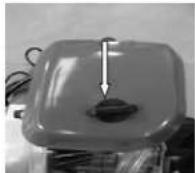
Fig 39 AIR FILTER

natural_image
Close-up of an electrical component with wires and a central housing (no visible text or symbols)Carburettor
- The carburetor mixture setting has been set at the factory and will not need adjusting.
- Adjusting the idle speed Fig 40. If adjustment is necessary turn the T screw clock wise until the blades start to move, then turn the screw T anticlockwise until the blades stop.
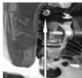
Fig 40
T screw
WARNING
If the idle speed cannot be adjusted to stop the cutting head moving at idle, contact your dealer for repair before use.
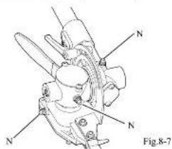
Inspecting the cutting blade
When the cutting edge becomes dull, the cutting blade will fall to cut cleanly and can exhibit blade thrust during operation. Using a broken, cracked or deformed blade carries a risk of blade fragments flying off during operation.
Inspection timing - Before and after operation
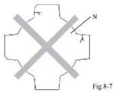
natural_image
Pure geometric cross shape diagram without any text, numbers, or symbols- Check that the cutting blade (N) as been correctly installed and that the blade clamping nut is not loose.
(See [5-2] Mounting the cutting blade or nylon trimmer.) 2.2 Check the cutting blade (N) or excessive wear, breakage
A. C. Check the clamping blade (n, of basilarve wall, brangle, cracks or deformation. If any such problems are found, replace the blade with a now one. Never use a damaged blade.
Gear Case
- Remove the bolt A on the gear base Fig 12, top up the gearbox using Lithium grease and refill the bolt.
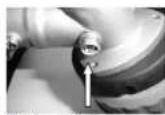
Fig 42 Bolt A
Inspection and Maintenance Checklist
| Checkpoints Before and after | operation | Every 20 Hours of operation | Every 50 hours of operation | Every 100 hours of operation | ||
| Engine | Loose screws, nuts and bolts | Inspect | ○ | |||
| Fuel leaks inspect | ○ | |||||
| Air conditioner | Inspect | ○ | ||||
| Clean | ○*1 | |||||
| Soark plug | Inspect and adjust | ○ | ||||
| Replace | ○ | |||||
| Engine cooling fins inspect and clean | ○ | |||||
| Muffler / exhaust port inspect and clean | ○ | |||||
| Clutch shoe inspect | ○*2 | |||||
| Fuel filter Clean | ○ | |||||
| Fuel tank Clean | ○ | |||||
| Carburetor | Inspect | ○ | ||||
| Entro Unit | Loose screws, nuts and bolts | Inspect | ○ | |||
| Broken, worn or missing parts | Inspect | ○ | ||||
| Breakage, wear, cracks or deformation. If the cutting blade or nylon trimmer, loose damping nuts | Inspect | ○ | ||||
| Grease in angle transmission | Replenish grease | ○ | ||||
*1 When using the machine in a dusty location, clean the air cleaner after every 10 hours of operation.
2 Clutch shoe replacement requires an appropriate tool kit and special maintenance techniques. We recommend that you ask your dealer to replace the clutch.
Long-term Storage
If the machine will not be started for 30 days or longer, maintain and store the machine as follows:
- Remove debris from the machine. Check the machine for damage and loose screws. Correct any problems so that the machine can be restarted later without a problem.
- Drain the fuel from the fuel tank. Start the engine and run it until no fuel remains in the carburetor. (The engine will stop automatically when no fuel remains.)
- Allow the engine to cool. Remove the spark plug and scurl a small amount of fresh engine oil into the spark plug hole. Slowly pull the recoil starter cord two or three times.
-
Reinstal the spark plug. Slowly pull the rocol starter cord and release it when you feel resistance. (This closes the intake and exhaust ports.)
-
Lightly wipe the external surface of the engine with cloth. Then, store the machine in a dry dust-free location where no open fire is present.
- Before storing the machine, clean the cutting blade and check for any irregularities. Install the blade cover provided as a standard accessory.
- Store the drained fuel in a safe container and keep it in a pool, dry room.
CAUTION
Do not store the machine for a prolonged period with fuel remaining in the fuel tank. Impurities in the fuel will deteriorate, adversely affecting the carburetor and fuel filter and possibly causing an engine malfunction. Always fully drain the fuel before storing the machine...
Troubleshooting
This troubleshooting section describes possible causes and remedies for problems you might encounter during operation of the machine. It is a problem persists after you have attempted the solutions recommended in this section, contact your dealer for technical assistance. Do not attempt to disassemble the machine.
Engine does not start
| Typical cause | Solution |
| The stop switch is in the STOP position.The fuel has deteriorated or is of poor quality.The carburetor is forced with excess fuel.The muffler exhaust pipe opening is blocked.The spark plug electrodes are failed. | Set the stop switch to the START position. Use fresh fuel of the correct grade.Turn the chase lever to the position opposite the START position. Pull the recoil starter cord repeatedly. Using a screwworker or other appropriate tool, remove the deposited carbon from the muffler.Clean the electrodes or replace the spark plug. |
Engine does not accelerate
| Typical cause | Solution |
| The tue has detonated or is of poor quality.The muffler exhaust pipe opening is blocked. | Use fresh tue of the correct grade.Using a screwdriver or other appropriate tool, remove the decorated carbon from the muffler |
Engine stalls when the throttle trigger is released
| Typical cause | Solution |
| The idle speed is too low. | Adjust the idle speed with the idle speed adjuster on the cathuretor |
Cutting blade continues to rotate after the throttle trigger is released
| Typical cause | Solution |
| The idle speed is too high.The throttle linkage has little or no play. | Adjust the idle speed with the idle-speed adjuster on the carburetorAdjust the play on the throttle linkage. |
Engine speed fluctuates
| Typical cause | Solution |
| The fuel filter is digged. | Clean or replace the fuel filter. |
Adnormal noise or vibration occurs
| typical cause Solution | |
| Blade or nylon trimmer is improperly installed.Cutting attachment guard or handlo is improperly installed.Camping screws are loose. | Check the cutting blade or nylon trimmer and reinstall if necessary.Check the cutting attachment guard or handle and reinstall it necessary.Check the clamping screws and retighten it necessary. |
Fuel consumption is high
| Typical cause Solution | |
| The air cleaner is clogged.The cutting blade has poor cutting performance. | Clean the air cleaner.Replace the cutting blade |
| Sections |
| Hruscutter 2 |
| Hedge Trimmer 18 |
| Pruning Saw 30 |
| Eoiger 44 |
| Cullivestor 52 |
About This Manual
Thank you for pursuing this product. This Instruction manual describes operating procedures and precautions as well as inspection and maintenance procedures for the machine. Before using the device, read this manual carefully until you are familiar with the contents. Carefully observe all warnings and safety instructions to ensure correct operation of the machine. Doing so will ensure safe operation and optimum performance of the device. This Instruction manual covers the attachments, controls, and engine of the Multi-Combination System. Use only attachments specified by the manufacturer. Use of any other attachment can result in damage to the eculentom, possibly loading to death or severe injury.
Be sure to strictly observe the important safety information that follows each bulleted term below. Failure to follow the instructions for correct operation contained herein can result in a severe accident.
⚠️ DANGER: Indicates that failure to follow the instructions creates an imminent hazard leading to death or severe injury.
⚠ WARNING: indicates that failure to follow the instructions has the potential to result in death or severe injury.
⚠️ CAUTION: Indicates that failure to follow the instructions can lead to minor injury or severe damage to the machine.
NOTE This is an auxiliary explanation that provides useful information and instructions.
Contents
| Meaning of oetognitions | 18 |
| Technical Data | 19 |
| Names of Parts | 20 |
| Safety Instructions | 21 |
| Enabling Safe Operation | 23 |
| Assembly | 24 |
| Wearing the Harness | 26 |
| Inspection and Maintenance | 26 |
| Long term Storage | 27 |
| Troubleshooting | 28 |
Meanings of Pictographs
| DANGER - WARNING - CAUTION | |
| Before using this device, read this manual carefully until you are familiar with the contents. | |
| Wear safety gear.1. Pane shed or protective goggles2. Head protection3. Far protection4. Heavy duty gloves5. Non slip safety shoes | |
| Keep your hands and feet a safe distance from the cutting blades while the hodge trimmer is in operation. | |
| · Keep the working end of the machine at least 15m away from overhead power lines, telephone wires, and all other cables.· Do not operate the device within 15 motors of a child, animal, or bystander. |
Technical Data - Hedge Trimmer
| Model | CG-260AF HTA 380 | |
| Masses | Unit with specified cutting attachment, empty tank | 6.48kg |
| Cutting Attachment | Type | Double reciprocating blade |
| Overall length (720mm extension & head) | 1255mm | |
| Effective cut length | 390mm | |
| Number of Tooth (Upper/Lower) | 26 / 28 | |
| Tooth pitch | 30mm | |
| Angle adjustment range | 90°(140°, 45° from cutting head position aligned shaft) | |
| External dimensions | Length (unit + 720mm extension & head) | 2255mm |
| Reduction ratio | 4:1 | |
Accessory
552796 Extension Pole 1000mm
Technical Data - Hedge Trimmer
| Model | CG-260AF HTA 500 | |
| Mases | Unit with specified cutting attachment, empty tank | 6.6kg |
| Cutting Attachment | Type | Double reciprocating bide |
| Overall length (/20mm extension & head) | 1430mm | |
| Effective cut length | 500mm | |
| Number of Tooth (Upper/Lower) | 36 / 36 | |
| Tooth pitch | 30mm | |
| Angle adjustment range | 1350^ +45^, -90^ from cuttinghead position aligned shaft | |
| External dimensions | Length (unit + 720mm extension & head) | 2430mm |
| Reduction ratio | 4:1 | |
Accessory
552796 Extension Pole 1000mm
Names of Parts
- Engine
- Spark plug
- Air cleaner cover
- Fuel tank gap
- Kure
- Ostechnik
- Crouch case 8. Carshulbany
II. Liptic bager - Twistle Mager, payout
- Stop switch
- Suspension point
- Shaft Tube
- Connector
- Knob
- Bna Ful
- Trimmer assembly
- George
- Cutting blades
- Blade cover
- Harness (supplied with the main unit)
Safety Instructions
- About This Manual CAUTION

This manual contains important safety instructions. Before doing this device, read this manual carefully until you are familiar with the contents. Carefully observe all warnings and safety instructions to ensure correct operation of the machine. Doing so will ensure safe operation and optimum performance of the device.
CAUTION
This instruction manual does not cover all possible situations and conditions. Although we have taken all possible steps to ensure the safety of this device, the operator and the person performing maintenance of the device must also take all possible steps to ensure safety.
2. Recommended Uses
CAUTION
Use the pole hedge trimmer only to trim hedges or cut twigs no larger than 5 mm in diameter.
3. Safe Practices
CAUTION
Follow local noise regulations regarding the acceptable times and locations for using this device. Also observe current local safety regulations, standards, and ordinances.
4. Replacement Parts
△WARNING
To maintain optimal safety and performance, use only the manufacturer's genuine parts and accessories. Do not modify the device or use it for purposes other than those specified. Failure to observe this requirement can result in severe accidents and damage to the device.
5. Operator Safety
WARNING
Do not operate this device if you.
• cannot concentrate due to fatigue, illness, or injury;
• are under the influence of drugs or alcohol
• are under the age of 15;
- are pregnant.
If any of the above apples, a possible lack of judgment can result in an accident.
6. Monitor the weather
WARNING

Fig.2-2
Do not operate the machine under any of the following circumstances:
- When the ground is slippery or you cannot maintain a stable posture for any reason.
- At night, in heavy fog, or at any other times where your field
of vision is limited and it is difficult to gain a clear view of the working area.
- During rainstorms, thunderstorms, in strong or gavelforce winds, or in any other adverse weather in which use of this device would be unassie.
7. Using Safety Gear
WARNING

• Always wear proper clothing when using this device.
- Tight-fitting, safe, and non-restricting clothing including a long-sleeved shirt, and a pair of trousers. (Avoid wearing shorts or baggy clothing.)
- Loose-fitting dotring can become entangled in a tree branch
or the like, posing the risk of tripping and resultant injury.
• Ear protection to protect your hearing
- Face shield or protective goggles
• Heavy-cuty gloves
• Non-slip safety shoes (Never operate this device while barefoot
or when wearing sandals,
• Head protection to protect your head from thrown objects, etc.
8. Basic Operations
CAUTION
• To ensure safe operation of this device, become familiar with
the safety Instructions and the procedure for shutting off the engine. See Starting and Stopping the Engine.
- In an emergency, it may be necessary to quickly release the machine from your body; therefore, familiarize yourself with the correct use of the harness quick release mechanism. (See Wearing the Harness • Quickrelease mechanism.)
9. Fuel Handling Precautions
DANGER


Fig.2-4
- Do not operate the machine near open flame or spilled fuel.
- Do not refuse while the engine is running or while the engine is still hot after shutting off the machine.
• Do not refuse while smoking - Thoroughly wipe away any applied fuel after refueling.
-
Start the engine at a occasion at least 3 meters away from the refueling area or the fuel container. Fuel is highly inflammatory, and a line can lead to death or severe injury.
-
Exhaust Gas Precautions
DANGER

Fig.25
Do not run the engine in a room or in any confined area where exhaust emissions can accumulate. Doing so can result in an accumulation of carbon monoxide and other poisonous gases that can cause death or severe poisoning.
- Cutting Blades Precautions
△ DANGER

Fig.2-6
- Keep your hands and feet a safe distance from the cutting blades while the backbone trimmer is in operation.
- If you need to touch the cutting blades in order to dislodge a twig or the like, first shut off the engine and allow the cutting blades to come to a full stop.
-
Even after the cutting blades have stopped, wear heavy-duty gloves and handle the cutting blades with care. The edges of the cutting blades are very sharp and can cause death or sovere injury.
-
The Hazard Area
WARNING

Fig.2-7
- Keep the working end of the machine at least 15 m away from overhead power lines, telephone wires, and all other cables. The machine is not insulated against external electric shock. Electric shock can lead to death or severe injury.
- Do not operate the device within 15 meters of a child, animal, or bystander. Consider a 15 meter radius around the device be a "hazard area."
-
If someone approaches the hazard area, immediately shut off the engine.
Operation of the machine can result in falling or lying objects that can lead to death or severe injury. -
Limit your worktime
WARNING
- Do not operate the machine for more than 2 hours a day.
-
Rest for 10 to 20 minutes after every 30 to 40 minutes of operation. Continuing to operate the machine without a break can result in excessive fatigue. The resulting loss of attentiveness can lead to an accident or problems with your fingers or hands. If you experience any abnormal symptoms such as pain, discomfort, or paralysis of the fingers or hand, immediately stop operating the machine and seek medical attention.
-
Avoiding Electric Shock
WARNING

Fig.2-8
Never touch the spark plug cap or high-voltage wire while the device is running. Doing so can result in a high-voltage electric shock that can cause death or severe injury.
- Avoiding Burns
△CAUTION

191020106.
Fig.2-9
Never touch the muffler, muffler cover, exhaust pipe, cylinder or cylinder head while the machine is running or immediately after operation, as they become very hot. Doing so can cause burns.
- Using the Blade Cover
CAUTION

natural_image
Technical line drawing of a mechanical assembly with no visible text or symbolsFig.2-10
- When the hedge trimmer is not being used, keep the blade cover on the cutting blades.
- Before transporting the hedge trimmer, shut off the engine and place the blade cover on the cutting blades. Transport the hedge trimmer with care. The cutting blades are sharp and can cause injury.
- If transporting the machine in a vehicle, secure it to prevent it from moving around. If the device can move freely during transport, the fuel can spill or the device can be damaged.
Ensuring Safe Operation
△CAUTION
To ensure safety, strictly observe the following instructions. Failure to do so can lead to personal injury or severe damage to the machine.
- Pre-operation inspection
Carefully inspect and perform any necessary maintenance before starting the machine. Failure to do so can lead to severe property damage or damage to the machine.
a. Tighten or replace loose or lost screws.
b. Replace any damaged or worn parts.
c. Check for soiled fuel. Check the fuel tank cap and wipe off any spilled fuel.
c. Check the cutting blances for chips, cracks, deformation, and excessive wear.
For more information, see Inspection and maintenance.
- Removing obstacles from the work area
Before starting operation, remove obstacles from the work area. Be extremely careful about obstacles that can trip the operator, such as tree roots, slumps, and holes.
- Marking the hazard area
A circular area within a radius of 15 meters of the machine is the hazard area. When necessary, mark the rope and post a warning sign.
- Wearing the Harness

Fig.3-1
- Put on the harness before starting to work with the machine.
-
Adjust the length of the harness belt so that you can hold the machine comfortably.
-
Starting the engine
-
In some cases, the cutting blades can suddenly begin to run when the engine is started. Keep a sale distance from the blades when starting the engine.
• Make sure that no bystanders are within 15 meters before starting the engine. - Place the machine on flat solid ground before starting the opening.
-
Ensure that nothing is in contact with the cutting blades, including the ground.
-
Preparing for work
Gain experience at first by cutting an imaginary hedge.
-
Safety Precautions

Fig.3-2 -
Hold the machine securely with both hands. Grip the control
handle with your right hand; hold the grip with your left hand. • To maintain a stable posture, adopt a stance wider than shoulder width. -
Maintain a firm footing.
- Shut off the engine if abnormal noise or vibration occurs, if an emergency occurs, or when pulling down the machine.
- If someone calls out or otherwise interrupts you while working, always shut off the engine before turning around.
- Plan a clear escape route should you need to avoid falling items.
- Before starting work, remove tree branches, leaves and other obstacles that can limit your field of vision.
- Determine the falling path of out debris based on the angle of the hodge or foliage being cut, the presence of obstacles, and the topography and wind direction.
-
To avoid injury from falling foliage, remain aware of the path of falling foliage while working. Do not stand right below the area you are cutting.
-
Cutting pattern
- Do not attempt to cut branches exceeding 5 mm in diameter. - When cutting longer branches or cutting deeply into a hedge, cut in several slaps.
- During the trimming work, the cutting blades can become jammed with twigs or get snagged by branches and the like. If this occurs, shut off the engine before removing the cause of the jam.
- Run the engine at speeds between 5,500 and 8,000 rpm to suit the working conditions.
-
Special precautions when two or more machines are in use. When two or more machines are in use simultaneously, it is essential that all operators use extreme care to maintain a safe distance from each other, constantly look around, and always remain aware of presence of the other operators to ensure safe operation.
-
Abnormal noise and vibration
-
If the machine suddenly exhibits abnormal noise or vibration, immediately shut off the engine.
- It abnormal vibration or noise occurs, check for damage to the cutting blades, loose screws, or other failure. Check the entire machine for any sign of a problem.
• After the cause has been found, do not use the machine until you have completed the repair.
Assembly
Attaching The Hedge Trimmer Gearbox
- Remove the locating screw (1)
- Using a Arm Alon key, loocet the clamping bolt (2).
- Slice the drive shaft (4) into the hedge trimmer gearbox (5) until the locating hole (6) in the drive shaft is visible through the locating hole (6) in the gearbox.
- Insert the locating screw (1) into the gear box (5) and tighten.
- Using a 4mm Alen key, tighten the clamping bolt (2).
NOTE
- The thickness of fresh growth (green branches), which may be cut using this hedge trimmer, is limited to up to approximately 10mm. Never try to cut branches thicker than this, as doing so may result in damage to the multi-tool.
Adjusting the angle of the cutting blades
- Stop the engine
- Turn the clamp bolt located on the top of the trimming mechanism, pulets, clavons to lapon it.
- Adjust the angle of the blades to the desired angle, and then tighten the bolt firmly back into place.
- Always wear gloves when adjusting the blades
Blade Information
- Never cut hedges thicker than 10mm and only fresh growth.
- If wire is caught by the blades, damage can occur which is no covered by the warranty.
- When sharpening, removing, or reattaching the blades, be sure to wear thick, sturdy gloves and use only appropriate tools and equipment to prevent injury.
- After you have finished using the hedge trimmer, clean the blades and apply clean light grade lubricating of to the entire length of the blades, including the blade bolts.
Attaching The Tools To The Drive Shaft Assembly
- Rest the power unit/snalt assembly on a flat firm surface
- Ensure that the clamping wing nut (2) is loose, pull out locator pin (1).
- Carefully fit attachment drive shaft assembly (5) into coupler (3).
- After the attachment drive shaft is in the coupler, reassess the locator pin (1).
- Turn the attachment drive shaft until the locator on engages
with the locating hole (4) in the drive
- shaft, when this has happened it will not be possible to twist the drive shaft.
- Secure the drive shaft by tightening the clamping wing nut (2).


Transportation
- Never transport the multi-tool with the engine running. An engine that's running could be accidentally accelerated causing the cutting blades to operate.
- Make sure the blade cover is in place when transporting the printer.
- When carrying by hand, the cutting blades should be pointing backward.

Wearing the Harness
NOTICE
The harness has a quick-release mechanism that allows you to immediately release the machine from the harness in an emergency.
Attaching the side hook
NOTICE
It side book (12) has disengaged from book (B), engage it.
-
Insert hook (B) into side hook (D).
-
While holding hook (B) and side hook (D) in place, insert sloopor (C) into the hole on hook (B).
Adjusting the harness

1. As shown in the diagram, adjust the harness (A).
- Before starting to work, attach the side hook (D) to the suspension point (F) on the shaft tube. (Fig.7-8)
Quick-release mechanism
WARNING
- In an emergency, release the throttle trigger and shut off the engine. Support the machine with your left hand and operate the quick release mechanism. The hedge trimmer will fall, and the cutting blades can cause death or severe injury while still running.
- Be careful not to accidentally operate the red belt (GI) on the
harness. The hedge trimmer will fall, and the cutting blades can cause death or severe injury while still running.

Fig.7-4
In an emergency, pull upward on the red bot (G) on the harness. This quickly releases the machine from the harness.
NOTICE
Before using the machine, check that the quick release mechanism is functioning.
8. Inspecting the cutting blades
If the cutting blades begin to wear excessively, the hedge bimmer will exhibit poor cutting performance, will fall to trim the hedge clearly, and will be difficult to use.
Inspection: liming - Before and after operation Check the cutting blades for excessive wear, breakage, cracking, deformation, and other problems. Replace the cutting blades assembly with a new one.
NOTICE
Before attempting to replace the cutting blades, contact your dealer for technical assistance.
9. Refilling the gearcase with grease
Although the gearcase has a mechanism to prevent grease leakage, a certain amount of grease loss is normal. Insufficient grease in the gearcase will accelerate gear wear.
Replenishment frequency Every 20 hours of operation
With a grease gun, inject grease through the three grease nipples (M).
10. Adjusting the gap of the cutting blades
Four screws secure the lower cutting blade to the upper blade. Adjust these screws to create sufficient gap between the upper and lower cutting blades to allow the blades to rectorocate freely. If the gap between the blades is insufficient, the cutting blades will not reciprocals; if the gap is too great, the cutting blades will not cut efficiently and will tend to become jammed with debris.
CAUTION
The cutting blades are very sharp. Wear heavy-duty gloves and handle the blades with care. The cutting blades are sharp and can cause injury.
Inspection liming Before and after operation
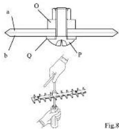
Fig.8-8
- Loosen the lock nut (O) (M6).
- Tighten the screw (P) until no gap is present between the upper
and lower blades. Then back off the screw by 1/3 to 1/2 tum. - With the screw (P) held in position, tighten the lock out (O) (M6).
- Confirm that you can turn the flat washer IQ with your finger.
a:Upper blade
b:Lower blade
11. Relubricating the cutting blades
If under-lubricated, the cutting blades will wear prematurely.
Inspection timing Before operation

Before starting the work, lubricate the cutting blades
with all
NOTICE
Even before completing work, reductricate the cutting blades when
refueling or when taking a break. Frequent reubrication will help
extend the service life of the cutting blades.
Inspection & Maintenance Checklist
| Checkpoints Before and after | operation | Every 20 Hours of operation | ||
| Entire Unit | Loose screws, nuts and bolts | Inspect | ○ | |
| Wear, breakage, cracks, and deformation of the cutting blades | Inspect | ○ | ||
| Grease in gearcase Rescience grease | ○ | |||
| Gap between cutting blades | Inspect | ○ | ||
| Oil lubrication of the cutting blades | Reubrose | ○ | ||
Long term storage
If the machine will not be started for 30 days of longer, maintain and store the machine as follows:
- Remove debris from the machine. Check the machine for damage and loose screws. Correct any problems so that the machine can be restored later without a problem.
- Drain the fuel from the fuel tank. Start the engine and run it until no fuel remains in the carburetor. (The engine will stop automatically when no fuel remains.)
- Allow the engine to cool. Remove the spark plug and scout a small amount of fresh engine oil into the spark plug hole. Slowly pull the recoil starter cord two or three times.
-
Reinstal the spark plug. Slowly pull the rocol starter cord and release it when you feel resistance. (This closes the intake and exhaust ports.)
-
Lightly wipe the external surface of the engine with cloth. Then, store the machine in a dry dust-free location where no open fire is present.
- Remove debris from the cutting blades. Check the cutting blades for irregularities. To prevent rusting, apply of springy to the surface of the cutting blades and attach the black cover (standard accessory).
CAUTION
Do not store the machine for a prolonged period with fuel remaining in the fuel tank. Impurities in the fuel will deteriorate, adversely affecting the carburetor and fuel filter and possibly causing an engine malfunction. Always fully clean the fuel before storing the machine.
Troubleshooting
This troubleshooting section describes possible causes and remedies for problems you might encounter during operation of the machine. If a problem persists after you have attempted the solutions recommended in this section, contact your dealer for technical assistance. Do not attempt to disassemble the machine.
Engine does not start
| Typical cause Solution | |
| The stop switch is in the STOP position.The fuel has deteriorated or is of poor quality.The carburetor is flooded with excess fuel.The muffor exhaust pipe opening is blocked.The spark plug electrodes are fouled. | Set the stop switch to the START position.Use their fuel of the current grade.Turn the choke lever to the position opposes the START position. Pull the recoil carrier cord repatably.Using a screwdriver or other appropriate tool, remove the deported carbon from the muffor.Clean the electrodes or replace the spark plug. |
Engine does not accelerate
| Typical cause Solution | |
| The fuel has deteriorated or is of poor quality.The muffler exhaust pipe opening is blocked. | Use fresh fuel of the correct grade.Using a screwdriver or other appropriate tool, remove the deposited carbon from the muffler |
Engine stalls when the throttle trigger is released
| Typical cause Solution | |
| • The idle speed is too low. • Adjust the idle speed with the idle-speed soluster on the carburetor | speed soluster on the carburetor |
Cutting blade continues to rotate after the throttle trigger is released
| Typical cause Solution | |
| The idle speed is too high.The throttle linkage has little or no play. | Adjust the idle speed with the idle speed adjuster on the carturetor.Adjust the play on the throttle linkage. |
Engine speed fluctuates
| Typical cause Solution | |
| • The fuel filter is clogged. • Clean or replace the fuel filter. |
Abnormal noise or vibration occurs
| Typical cause Solution | |
| • Clamping screws are loose • Check the clamping screws and relighten if necessary. | |
Fuel Consumption is high
| Typical cause Solution | |
| The air cleaner is clogged.Culling blades occur their cutting performance. | Clean the air cleanerReplace the cutting blades |
| Sections |
| Hruscutter 2 |
| Hedge Trimmer 18 |
| Pruning Saw 30 |
| Eoiger 44 |
| Cullivestor 52 |
About This Manual
Thank you for purchasing this product. This Instruction manual describes operating procedures and precautions as well as inspection and maintenance procedures for the machine. Before using this device, read this manual carefully until you are familiar with the contents. Carefully observe all warnings and safety instructions to ensure correct operation of the machine. Doing so will ensure safe operation and optimum performance of the device. This Instruction manual covers the attachments, controls, and engine of the Multi-Combination System. Use only attachments specified by the manufacturer. Use of any other attachment can result in damage to the equipment, possibly leading to death or severe injury. Be sure to strictly observe the important safety information that follows each bulleted term below. Failure to follow the instructions for correct operation contained herein can result in a severe accident.
△ DANGER: Indicates that failure to follow the instructions creates an imminent hazard leading to death or severe injury. △ WARNING: Indicates that failure to follow the instructions has the potential to result in death or severe injury. △ CAUTION: Indicates that failure to follow the instructions can lead to minor injury or severe damage to the machine.
NOTE This is an auxiliary explanation that provides useful information and instructions.
Contents
| Meaning of octograsons | 30 |
| Technical Data | 31 |
| Names of Parts | 32 |
| Safety Instructions | 33 |
| Ensuing Safe Operation | 35 |
| Assembly | 36 |
| Wearing the Harness | 39 |
| Inspection and Maintenance | 40 |
| Long-term Storage | 41 |
| Troubleshooting | 42 |
Meaning of Pictographs
| DANGER - WARNING - CAUTION | |
| Before using this device, read the manual carfully until you are familiar with the contents. | |
| Face shield or protective goggles. | |
| Wear safety gear.1. Face shield or protective goggles2. Head protection3. Ear protection4. Heavy-duty gloves5. Non-slip safety shoes | |
| · Keep the working end of the machine at least 15 m away from overhead power lines, telephone wires, and all other cables.· Do not operate the device within 15 motors of a child, animal, or bystander. | |
| Turning the chain oil flow adjuster clock wise compresses the chain of feed rate; turning the adjuster counterclockwise increases the chain oil feed rate. | |
| (1) Turn the locking screw of the chain oil flow adjuster counterclockwise by one full turn to unlock the chain oil flow adjuster.(2) Aducts the chain oil feed rate with the chain oil flow adjuster.(3) After adjusting the chain of feed rate, turn the locking screw of the chain oil flow adjuster clockwise to lock the chain oil flow adjuster. |
Technical Data - Pruner Saw
| Mases | Unit with specified cutting attachment, empty tank | 5.74kg |
| Cutting Attachment | Type | Pruner Saw |
| Overall length (715mm pruning saw & 330 saw) | 1045mm | |
| Saws chains length | 225mm | |
| Tooln Pitch and Gauge | 3/8 x 0.042" (9.53 x 1.07mm) | |
| Number of drive links | 30 | |
| Chain specification | Oregon LY/T1187 JL9-3 | |
| Guido bar skis | 10" (250mm) | |
| Scrovet | 7T | |
| Oil tank volume | 100mL | |
| Oil pump | Punger type | |
| External dimensions | Length (Unit & Pruning Saw + Chain) | 2045mm |
| Reduction ratio | 17:18 (0.94) | |
| Gearbox Lubrication | Multipurpose Lithium-based grease | |
| Head Angle Adjustment | 0° | |
Accessory
552796 Extension Pole 1000mm
Names of Parts
- Engine
- Spark plug
- Air cleaner cover
- Fuel tank cap
- Muller
- Throttle linkage
- Cutch case
- Control handle
- Throttle trigger
- Treltle trigger lockout
- Stop switch
- Suspension point
- Shaft tube
- Connector
- Knob
- Ring Pull
- Gearcase
- Saw chain
- Guide bar
- Guide bar cover
- Harness (Supplied with Main Unit)
Safety Instructions
1. About This Manual
CAUTION

Fig.2-1
This manual contains important safety instructions. Before doing this device, read this manual carefully until you are familiar with the contents. Carefully observe all warnings and safety instructions to ensure correct operation of the machine. Doing so will ensure safe operation and optimum performance of the device.
CAUTION
This instruction manual does not cover all possible situations and conditions. Although we have taken all possible steps to ensure the safety of this device, the operator and the person performing maintenance of the device must also take all possible steps to ensure safety.
2. Recommended Uses
CAUTION
Use the pole pruning saw for delimbing trees and bucking at height. Do not use the pruning saw to fall trees or trim branches thicker than 15 cm.
3. Safe Practices
CAUTION
Follow local noise regulations regarding the acceptable times and locations for using this device. Also observe current local safety regulations, standards, and ordinances.
4. Replacement Parts
WARNING
To maintain optimal safety and performance, use only txhe manufacturer's genuine parts and accessories. Do not modify the device or use it for purposes other than those specified. Failure to observe this requirement can result in severe accidents and damage to the device.
5. Operator Safety
WARNING
Do not operate this device if you..
• cannot concentrate due to fatigue, illness, or injury;
• are under the influence of drugs or alcohol
• are under the age of 15;
- are pregnant.
If any of the above apples, a possible lack of judgment can result in an accident.
6. Monitor the weather
WARNING

Fig.2-2
Do not operate the machine under any of the following circumstances:
- When the ground is slippery or you cannot maintain a stable posture for any reason.
- At night, in heavy fog, or at any other times where your field of vision is limited and it is difficult to gain a clear view of the working area.
-
During rainstorms, thunderstorms, in strong or geForce winds, or in any other adverse weather in which use of this device would be unsafe.
-
Using Safety Gear WARNING

Fig.2-3
Always wear proper clothing when using this device.
- Tight-fitting, safe, and non-restricting clothing including a long-sleeved shirt and a pair of trousers. (Avoid wearing shorts or baggy clothing.)
Loose-fitting clothing can become entangled in a tree branch or the like, posing the risk of tripping and resutant injury.
• Ear protection to protect your hearing
• Face shield or protective goggles - Heavy-duty gloves
- Non-slip safety shoes (Never operate this device while barefoot or when wearing sandals.)
• Head protection to protect your head from thrown objects, etc.
8. Basic Operations
CAUTION
- To ensure safe operation of this device, become familiar with the safety Instructions and the procedure for shutting off the engine. (See Starting and Stopping the Engine.)
- In an emergency, it may be necessary to quickly release the machine from your body. Therefore, familiarize yourself with the correct use of the hamea quick release mechanism.
[See Wearing the Harness - Quickrelease mechanism.]
- Fuel Handling Precautions
⚠️ DANGER


Fig.2-4
- Do not operate the machine near open flame or spilled fuel.
- Do not refuel while the engine is running or while the engine is still hot after shutting off the machine.
• Do not refuse while smoking. - Thoroughly wipe away any applied fuel after refueling.
-
Start the engine at a occasion at least 3 meters away from the refueling area or the fuel container. Fuel is highly inflammatory, and a line can lead to death or severe injury.
-
Exhaust Gas Precautions
DANGER

Fig.2-5
Do not run the engine in a room or in any confined area where exhaust emissions can accumulate. Doing so can result in an accumulation of carbon monoxide and other poisonous gases that can cause death or severe poisoning.
- Saw Chain Precautions
DANGER

Fig.2-6
- Do not allow your hand or foot to approach a pruning saw chain in operation.
- If you must touch the pruning saw chain in order to remove an entangled branch or the lke, turn off the main unit and wait for the pruning saw chain to fully stop.
- Even after the pruning saw chain has stopped, wear heavy-duty gloves and handle the chain with care. The cutting edges of the pruning saw chain are very sharp and can cause death or severe injury.
- The Hazard Area
WARNING

Fig.2-7
- Keep the working end of the machine at least 15 m away from overhead power lines, telephone wires, and all other cables. The machine is not insulated against external electric shock. Electric shock can lead to death or severe injury.
- Do not operate the device within 15 meters of a child, animal, or bystander. Consider a 15 meter radius around the device to be a "hazard area."
- If someone approaches the hazard areas, immediately shut off the engine.
Operation of the machine can result in falling or lying objects that can lead to death or severe injury.
- Limit your worktime
WARNING
- Do not operate the machine for more than 2 hours a day. - Rest for 10 to 20 minutes after every 30 to 40 minutes of population.
Continuing to operate the machine without a break can result in excessive fatigue. The resulting loss of attentiveness can lead to an accident or problems with your fingers or hands. If you experience any abnormal symptoms such as pain, discomfort, or paralysis of the fingers or hands, immediately stop operating the machine and seek medical attention.
- Avoiding Electric Shock
WARNING

Fig.2-8
Never touch the spark drug cap or high voltage wire while the device is running. Doing so can result in a high-voltage electric shock that can cause death or severe injury.
- Avoiding Burns
CAUTION

Fig.2-9
Never touch the mutter, mutter cover, exhaust pipe, cylinder or cylinder head while the machine is running or immediately after operation, as they become very hot. Doing so can cause burns.
- Using the Guide bar cover
CAUTION
natural_image
Technical line drawing of a chain-linking tool with an arrow indicating motion (no text or symbols present)Fig.2-10
- Keep the guide bar cover on the pruning saw chan when the pruning saw is not in use.
- Before transporting the pruning saw, shut off the engine and till the guice bar cover on the pruning saw chain. Exercise care when transporting it. The pruning saw chain is a very sharp tool and can cause injury.
- If transporting the machine in a vehicle, secure it to prevent it from moving around. If the device can move freely during transport, the fuel can spill or the device can be damaged.
Ensuring Safe Operation
CAUTION
To ensure safety, strictly observe the following instructions. Failure to do so can lead to personal injury or severe damage to the machine.
- Pre-operation inspection
Carefully inspect and perform any necessary maintenance before starting the machine. Failure to do so can lead to severe property damage or damage to the machine.
a. Tighten or replace loose or lost screws.
b. Replace any damaged or worn parts.
c. Check for spilled fuel. Check the fuel tank cap and
wipe off any spilled fuel.
c. Check that the saw chain is correctly tensioned.
e. Check the level of chain oil in the oil tank.
For more information, see inspection and maintenance.
- Removing obstacles from the work area
Before starting operation, remove obstacles from the work area. Be extremely careful about obstacles that can trip the operator, such as tree roots, stumps, and holes.
- Marking the hazard area
A circular area within a radius of 15 meters of the machine is the hazard area. When necessary, mark the post a warning sign.
- Wearing the Harness

Fig.3-1
- Put on the harness before starting to work with the machine. - Adjust the length of the harness belt so that you can hold the machine comfortably.
- Starting the engine
- In some cases, the saw drain can begin to run suddenly when the engine is started. Maintain a safe area around you before starting the engine.
• Make sure that no bystanders are within 15 motors before starting the engine.
- Place the machine on flat solid ground before starting the engine.
• Make sure that no portion of the saw chain is in contact with the ground or other object.
- Checking the chain oil feed rate
Before starting the work, check that the chain oil is fed at the correct rate. To do so, start the engine and allow the saw chain to run. Point the end of the guide bar at a wood board or other flat surface without allowing the saw chain to touch the board. Run the chainsaw at a fairly high speed for 2 to 3 seconds. If a small amount of chain oil has splashed onto the board, the chain of feed rate is appropriate.
For the procedure on adjusting the chain oil feed rate, see 13. Adjusting the chain oil feed rate under inspection and Maintenance.
- Preparing for work
Gain experience at first by cutting small twigs and branches.
- Safety Precautions

Fig.3.2
- Hold the machine securely with both hands. Grip the control handle with your right hand; hold the grip with your left hand.
• To maintain a stable posture, adopt a stance wider than shoulder width.
- Maintain a firm fact no
- Shut off the engine if abnormal noise or vibration occurs, if an emergency occurs, or when putting down the machine.
• If someone calls out or otherwise interrupts you while working, always shut off the engine before t mino around.
- Plan a clear escape route should you need to avoid falling items.
- Before starting work, remove tree branches, leaves and other obstacles that can limit your field of vision.
- Determine the falling path of cut branches based on the angle of the trunk, surrounding branches and talgs, the location of neighboring trees, the presence of obstacles, and the topcorsory and wind direction.
• To avoid injury from falling branches, remain aware of the path of falling branches while working. Do not stand right below the branches you are cutting.
- Cutting pattern
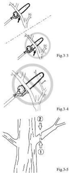
- Do not attempt to cut branches exceeding 15 cm in diameter.
- If it is necessary to cut a thick branch, cut it in several stages.
- If the saw chain becomes is immed in a branch during
Operation, or if the saw chain becomes enlarged with a branch, shut off the engine before attempting to free up the saw chain. - Run the engine at speeds between 5.500 and 8.000 rpm to suit the working conditions.
- Be extremely careful about the possibility of kickback when cutting bent or soil branches.
- Press the guide on the gearcase against the branch you intend to cut. With this technique, the running saw chain will not reach forward when the branch has been cut through. Do not allow a gap between the guide and branch being cut; do not move the saw chain back and forth. (Fig.3-3)
- If another branch is immediately behind the branch being cut, use extreme caution. The second branch can cause the guide bar to break. (Fig.3-4)
- When cutting a branch, lightly push the saw chain against it. Immediately before cutting through the branch, stop pressing and hold the chinsaw securely.
• To cut a thick branch exceeding 10 cm in diameter, do the following: (Fig.3-5)
- Lightly press the upper side of the guide bar against the underside of the branch near the trunk. Make the undercut (1) to a depth of about 1/4 the diameter of the branch.
- Make a backout (2) from above the branch, at a location about 2 to 3 cm outside the undercut. Once the branch has fallen, cut off the remaining part near the trunk.
10. Kickback
Never use the leading end of the guide bar (especially not the leading 1/4 near the tip) to cut a branch. If the leading end of the guide bar contacts a tree, branch, or other hand object while the saw chain is running, violent kickback will occur. Kickback is a violent reaction force that causes the chainsaw to swing back toward the operator, possibly leading to injury.
11. Special precautions when two or more machines are in
When two or more machines are in use simultaneously, it is essential that all operators use extreme care to maintain a safe distance from each other, constantly lock around, and always remain aware of presence of the other operators to ensure safe operation.
12. Abnormal noise and vibration
- If the machine suddenly exhibits abnormal noise or vibration, immediately shut off the engine.
- If abnormal noise or vibration occur, check for damage to the saw chain, a loose screw, or other failure. Check the entire machine for any sign of a problem.
• After the cause has been found, do not use the machine until you have completed the repair.
Assembly of the Pruner
Attaching The Pruning Mechanism (Fig 17)
- Remove the locating screw (5).
- Using a 4mm Alen key, cosen the clamping bolt (4).
- Side the drive shaft (1) into the gearbox (2) until the locating hole (3) in the drive shaft is visible through the locating hole in the gearbox (5).
- Insert the locating screw (5) into the gearbox (2) and tighten.
- Using a 4mm Alan key, tighten the clamping bolt (4).
Fig 17
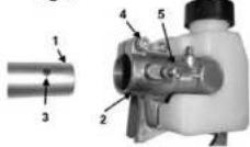
Install the guide bar and the saw chain on the gearbox as
follows: (kg 18)
(1) Guide bar
(2) Saw chan
(2) Gearbox
(4) Sprookel
(c) Chain tension adjust screw
(3) Nut
(7) Chain tensioner
(2) Chain cover
Fig 18

WARNING
The saw chain has very sharp edges. Use protective gloves for safety.
- Loose the nut 6, Fig 18/20 and remove the chain cover 8.
- Mount the guide bar, then til the saw chain around the bar and sprocket Fig 19.
Fig 19

Pay attention to the correct direction of the new chain Fig. 19.

- Fit the chain tensioner into the lower hole of the guide bar, then install the chain cover, and fasten the mounting nut to finger tightness. Fig 20.
- Turn the adjuster screw 1 clockwise until the chain does not sag from the underside of the guide bar Fig 21.
- Tighten the chain cover nut.
- Pull the chain around the guide bar by hand to check that the chain has the correct tension, without any tight spots.
Fig 21

It is important to maintain the proper chain tension. Rapid wear of the guide bar or the chain coming off can be caused by improper tension, especially when using a new chain.
Chain Oil
- Fill the chan oil tank 2 with low viscosity chan oil or 10W30 (Fig 22.)

NOTE
- Do not use waste or regenerated oil that can cause damage to the oil pump.
- The oil reservoir has a capacity sufficient to provide about 20 minutes of cutting time (when set to deliver the minimum flow rate). Be sure to refill the oil tank every time when retueling the saw.
Checking the oil supply
- After starting the engine, run the chain at medium speed and see it chain oil is thrown off as shown in the figure Fig. 23.
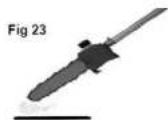
Adjusting Oil Flow Rate
WARNING
Never fill the oil reservoir or adjust the oiler with the engine running.
• An increase in bar oil flow rate will speed oil consumption.
- The guine bar and chain are lubricated automatically by a pump that operates whenever the chain rotates. The pump is set at the factory to deliver a minimum flow rate, but it can be adjusted in the field. A temporary increase in oil flow is often desirable when cutting hardwood.
Adjust the pump as follows:
- Step the engine and make sure the stop switch is in the OFF position.
- Place the unit on its side with the oil reservoir (5) up.
- The oil flow adjusting screw must be pressed in slightly in order to turn. Failure to do so could damage the pump and screw (Fc 24).
- With a screwdriver, push in on the oil flow rate adjusting screw and turn in the desired direction (there are three incremental settings)
- Clockwise-decrease lubrication, Counter clockwise-increase lubrication.

Fig 24
Bar And Chain Maintenance
- Dismount the guide bar and check the ciling port for blockage (Fig 25.)
- Remove sawdust in the bar groove (1) and the oiling port (2) (Fig 26.)
- Grease the nose sprocket (2) from the feeding port on the tip of the bar (1) (Fig 27) with a sprocket grease gun
Pruning Saw Chainsaw
WARNING It is very important for smooth and safe operation to always keep the chain sharp.
The chain needs to be sharpened when: - Sawdust becomes powder-like. - You need extra torpe to saw - The cut does not go straight.
Saw chain sharpening:
WARNING Be sure to wear safety gloves.
- Remove multi-tool from power unit.
- Clamp mult-look guide bar in a vice to secure.
- Sharpen chain with a 6/32 file and holder
- Place your file on the cutter and push straight forward. Keep the 11e position as illustrated. (Eq 28)
• After every cutter has been set, check the depth gauge and lie it to the proper level as illustrated (Fig 29).
• Make sure every cutter has the same length and edge angles as illustrated (Fig 30).
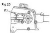
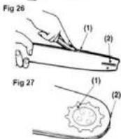
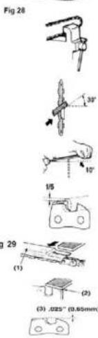
(1) Depth gauge set tool
(2) File shoulder round
(3) Depth gauge standard
(4) Cutter length
(5) Fling angle
(6) Side plate angle
(7) Top plate cutting angle
Gearbox
Gearbox Lubricant
- Always use lithium based grease. - DO NOT force grease into the gear box, apply 2 or 3 pumos of grease every 15 hours of operation Fig 31.
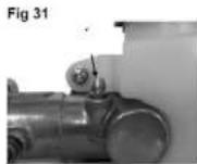
Kickback And Pinching Safety Precautions Beware of kickback!
- Kickback can occur whenever the up of the guide bar touches an object while the saw is operating. Kickback may force the bar up and back towards the operator with speed!
Beware of pinching.
- Pinching the saw along the tip of the guide bar may force the bar back rapidly toward the operator. Pinching can occur whenever wood closes in around the moving chain.
WARNING
- Both kickback and ponching may cause you to lose control of the pole orner which could result in serious personal injury.
- Undejected kickback and onopical
- Keep a firm grip on the pole prune with both hands whenever the engine is running. A firm grip will help you reduce the effects of kickback and pinching as well as maintain control of the machine.
• Cut at high engine speeds. - Follow the manufacturer's instructions for sharpening and maintaining the chain.
- Use only genuine spare parts.
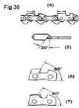
Wearing the Harness
NOTICE
The harness has a quick-release mechanism that allows you to immediately release the machine from the harness in an emergency.
Attaching the side hook

NOTICE
It side hook (D) has disengaged from hook (B), engage it. 1. Insert hook (P) into side hook (D).
- While holding hook (B) and side hook (D) in place, insert slobber (C) into the hole on hook (B).
Adjusting the harness

- As shown in the diagram, adjust the harness (A).

- Before starting to work, attach the side hook (D) to the suspension point (F) on the shaft tube. (Fig.7-3)
Quick-release mechanism
WARNING
- In an emergency, release the throttle trigger and shut off the engine. Support the machine with your left hand and operate the quick release mechanism. The hedge trimmer will fall, and the cutting blades can cause death or severe injury while still running.
- Be careful not to accidentally operate the red belt (GI) on the
harness. The hedge trimmer will fail, and the cutting blades can cause death or severe injury while still running.
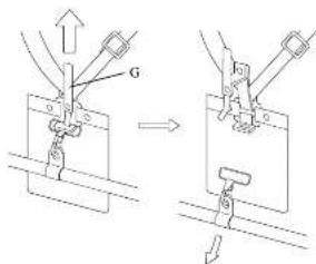
Fig.7-4
In an emergency, pull upward on the red bot. (GI) on the harness. This quickly releases the machine from the harness.
NOTICE
Before using the machine, check that the quick release mechanism is functioning.
Inspection and Maintenance
Cleaning the chain oil discharge xport, guide bar, and drive sprocket cover
These areas can easily become clogged with chain oil and wood chips. Clean these areas frequently.
Cleaning frequency - Before and after operation, Frequently
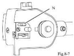
natural_image
Technical line drawing of a mechanical clamp or connector (no text or symbols)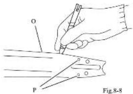

natural_image
Illustration of a hand holding a tool with a labeled component (no text or symbols present)- Remove the guide bar camping nut.
- Remove the guide car slot uses
- Clean the chain of discharge port (N). (Fig.8-7)
- Using the options' depth gags, clean the oil filler hole and the slot (O) on the guide bar (P), (Fig.8-8)
- Wipe away any wood chips and other debris that has accumulated in the drive sprocket cover (Q). (Fig.8-9)
-
Install the guide bar and saw chain while referring to Assembly of Pruner.
-
Inspecting the saw chain
If the saw chain (R) wears excessively, the chainsaw will exhibit poor cutting performance, will fail to cut branches cleanly, and will be difficult to use.
Inspection timing Before and after operation

Check the saw chain for excessive wear, breakage, cracks, deformation, and other problems. Replace a problem saw chain with a new one.
- Inspecting the saw chain tension
Make sure that the saw chain is correctly tensioned.
Inspection timing - Before and after operation To adjust the tension of the saw chain, see Assembly of Pruner.
- Replenishing the chain oil
If you continue to run the chamsaw oven after all the chain oil has been depleted, the saw chain and guice bar will soon become damaged beyond repair.
Inspection timing - Before and after operation
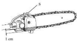
Fig.8-11
NOTE
- Use a high quality special chain oil suitable for the chainsaw
- Add fresh chain oil before the oil level drops to the line indicating 1 cm above the bottom of the oil tank.
- If chan oil is soiled on the chairsaw, thoroughly wipe off the spill and surrounding stress.
- Dust or other foreign matter in the oil tank can cause the chainsaw to malfunction. Be careful to prevent dust and other foreign matter from contaminating the oil tank.
- Remove the tank cap (SI)
- Pour the chain oil into the chain oil tank.
- Replace the tank esp (5).
Inspection & Maintenance Checklist
| Checkpoints Before and after | operation | Every 20 Hours of operation | Every 50 Hours of operation | ||
| Entire Unit | Loose screws, nuts and bolts | Inspect | ○ | ||
| Cleaning of the chain oil discharge port, guide bar, and drive sprocket cover | Clean | ○ | |||
| Excessive wear, break-ago, cracks, and deformation of the saw chain | Inspect | ○ | |||
| Tenacn of the saw chain | Inspect | ○ | |||
| Chain oil feed | Inspect | ○ | |||
| Chain oil feed rate | Inspect | ○ | |||
| Cleaning of the oil filler | Clean | ○ | |||
| Grease in gearcase | Replenish groove | ○ | |||
Long term storage
If the machine will not be started for 30 days of longer, maintain and store the machine as follows:
- Remove debris from the saw chain. Check the saw chain for irregularities. To prevent rusting, sparingly apply oil onto the surface of the saw chain and install the guide bar cover provided as a standard accessory
CAUTION
Do not store the machine for a prolonged period with fuel remaining in the fuel tank. Impurities in the fuel will deteriorate, adversely affecting the carburetor and fuel filter and possibly causing an engine malfunction. Always fully drain the fuel before storing the machine.
Troubleshooting
This troubleshooting section describes possible causes and remedies for problems you might encounter during operation of the machine. If a problem persists after you have attempted the solutions recommended in this section, contact your dealer for technical assistance. Do not attempt to disassemble the machine.
Engine does not start
| Typical cause Solution | |
| The stop switch is in the STOP position.The fuel has deteriorated or is of poor quality.The carburetor is flooded with excess fuel.The muffor exhaust pipe opening is blocked.The spark plug electrodes are fouled. | Set the stop switch to the START position.Use their fuel of the current grade.Turn the choke lever to the position opposes the START position. Pull the recoil carrier cord repatably.Using a screwdriver or other appropriate tool, remove the deported carbon from the muffor.Clean the electrodes or replace the spark plug. |
Engine does not accelerate
| Typical cause Solution | |
| The fuel has deteriorated or is of poor quality.The muffler exhaust pipe opening is blocked. | Use fresh fuel of the correct grade.Using a screwdriver or other appropriate tool, remove the deposited carbon from the muffler |
Engine stalls when the throttle trigger is released
| Typical cause Solution | |
| • The idle speed is too low. • Adjust the idle speed with the idle-speed soluster on the carburetor | speed soluster on the carburetor |
The saw chain continues to run though the throttle trigger has been released.
| Typical cause Solution | |
| The idle speed is too high.The throttle linkage has little or no play. | Adjust the idle speed with the idle speed adjuster on the carburetor.Adjust the play on the throttle linkage. |
Engine speed fluctuates
| Typical cause Solution | |
| • The fuel filter is clogged. • Clean or replace the fuel filter. |
Abnormal noise or vibration occurs
| Typical cause Solution | |
| • Clamping screws are loose • Check the clamping screws and relighten if necessary. | |
Fuel Consumption is high
| Typical cause Solution | |
| The air cleaner is clogged.Saw chain is requiring more effort to cut | Clean the air cleanerSharpen or replace the saw chain |
| Sections |
| Hruscutter 2 |
| Hedge Trimmer 18 |
| Pruning Saw 30 |
| Eoiger 44 |
| Cullivestor 52 |
About This Manual
Thank you for purchasing this product. This Instruction manual describes operating procedures and precautions as well as inspection and maintenance procedures for the machine. Before using this device, read this manual carefully until you are familiar with the contents. Carefully observe all warnings and safety instructions to ensure correct operation of the machine. Doing so will ensure safe operation and optimum performance of the device. This Instruction manual covers the attachments, controls, and engine of the Multi-Combination System. Use only attachments specified by the manufacturer. Use of any other attachment can result in damage to the equipment, possibly leading to death or severe injury. Be sure to strictly observe the important safety information that follows each bulleted term below. Failure to follow the instructions for correct operation contained herein can result in a severe accident.
△ DANGER: Indicates that failure to follow the instructions creates an imminent hazard leading to death or severe injury. △ WARNING: Indicates that failure to follow the instructions has the potential to result in death or severe injury. △ CAUTION: Indicates that failure to follow the instructions can lead to minor injury or severe damage to the machine.
NOTE This is an auxiliary explanation that provides useful information and instructions.
Contents
| Meaning of pictograms | 44 |
| Technical Data | 45 |
| Names or Parts | 46 |
| Safety Instructions | 47 |
| Ensuing Sale Operation | 48 |
| Assembly | 49 |
| Wearing the Harness | 49 |
| Inspection and Maintenance | 50 |
| Troubleshooting | 51 |
Meaning of Pictographs
| DANGER - WARNING - CAUTION | |
| Below using this device, read this manual carefully until you are familiar with the contents. | |
| Wear safety gear.1. Face shod or protective goggles2. Head protection3. Far protection4. Heavy-duty gloves5. Non slip safety shoes | |
| · Keep the working end of the machine at least 15 m away from overhead power lines, telephone whls, and all other cables.· Do not operate the device within 15 meters of a child, animal, or bystander. | |
Technical Data - Edger
| Masses | Unity with specified cutting attachment, empty tank | 5.96kg |
| Cutting Attachment | Type | Edgar |
| Overall length (length to angle transmission) | 720mm | |
| Effective cut depth | 80mm | |
| Blade Thickness | 2.5mm | |
| Blade Length | 200mm | |
| Cutting Blades per revolution | 2 | |
| External dimensions | Length (Unit & Edgar) | 1720mm |
| Reduction ratio | 22:17 | |
| Gearbox Lubrication | Multipurposelithium-based grassa | |
Names of Parts
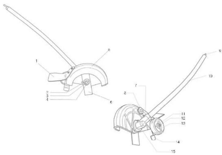
- Guard-rubber
- Blade Hocker
- Nut
- Safety Split Pr
- Guard
- Plaza
- Clempez Boi M6-20
- Hand Nut
- Inner Spline
- Drive Shaft
- Washer M6
- MS Nylon Nut
- Whoc
- Guoe
- Angle transmission
Safety Instructions
1. About This Manual
CAUTION

Fig.2-1
This manual contains important safety instructions. Before using this device, read this manual carefully until you are familiar with the contents. Carefully observe all warnings and safety instructions to ensure correct operation of the machine. Doing so will ensure safe operation and optimum performance of the device.
CAUTION
This instruction manual does not cover all possible situations and conditions. Although we have taken all possible steps to ensure the safety of this device, the operator and the person performing maintenance of the device must also take all possible steps to ensure safety.
2. Recommended Uses
CAUTION
This machine should never be used for anything other than the purpose for which it has been designed. Use the edge only to trim lawn edges.
3. Safe Practices
CAUTION
Follow local noise regulations regarding the acceptable times and locations for using this device. Also observe current local safety regulations, standards, and ordinances.
4. Replacement Parts
△WARNING
To maintain optimal safety and performance, use only the manufacturer's genuine parts and accessories. Do not modify the device or use it for purposes other than those specified. Failure to observe this requirement can result in severe accidents and damage to the device.
5. Operator Safety
WARNING
Do not operate this device if you.
• cannot concentrate due to fatigue, illness, or injury;
• are under the influence of drugs or alcohol
• are under the age of 15;
- are pregnant.
If any of the above apples, a possible lack of judgment can result in an accident.
6. Monitor the weather
WARNING

Fig.2-2
Do not operate the machine under any of the following circumstances:
- When the ground is slippery or you cannot maintain a stable posture for any reason.
- At night, in heavy fog, or at any other times where your field
of vision is limited and it is difficult to gain a clear view of the working area.
- During rainstorms, thunderstorms, in strong or gasketorce winds, or in any other adverse weather in which use of this device would be unasis.
7. Using Safety Gear
WARNING

Fig.2-3
• Always wear proper clothing when using this device.
- Tight-fitting, safe, and non-restricting clothing including a long-sleeved shirt, and a pair of trousers. (Avoid wearing shorts or baggy clothing.)
- Loose-fitting dotring can become entangled in a tree branch
or the like, posing the risk of tripping and resultant injury.
• Ear protection to protect your hearing
- Face shield or protective goggles
• Heavy-cuty gloves
• Non-slip safety shoes (Never operate this device while barefoot
or when wearing sandals,
• Head protection to protect your head from thrown objects, etc.
8. Basic Operations
CAUTION
• To ensure safe operation of this device, become familiar with the safety instructions and the procedure for shutting off the engine.(See Starting and Stopping the Engine.)
- In an emergency, it may be necessary to quickly release the machine from your body; therefore, familiarize yourself with the correct use of the harness quick release mechanism. (See Wearing the Harness • Quickrelease mechanism.)
9. Fuel Handling Precautions
DANGER


Fig.2-4
- Do not operate the machine near open flame or spilled fuel.
- Do not refuse while the engine is running or while the engine is still hot after shutting off the machine.
• Do not refuse while smoking. - Thoroughly wipe away any applied fuel after refueling.
-
Start the engine at a occasion at least 3 meters away from the refueling area or the fuel container. Fuel is highly inflammatory, and a line can lead to death or severe injury.
-
Exhaust Gas Precautions
DANGER

Fig.2.5
Do not run the engine in a room or in any confined area where exhaust emissions can accumulate. Doing so can result in an accumulation of carbon monoxide and other poisonous gases that can cause death or severe poisoning.
- Cutting Blades Precautions
DANGER

Fig.2-6
- Keep your hands and feet a safe distance from the cutting blades while the edge is in operation.
- If you need to touch the cutting blades, first shut off the engine and allow the cutting blades to come to a full slip.
- Even after the cutting blades have slopped, wear heavy-duty gloves and handle the cutting blades with care. The edges of the cutting blades are very sharp and can cause death or severe injury.
12. The Hazard Area
WARNING
- Keep the working end of the machine away from power cables, telephone wires, and all other cables. The machine is not insulated against external electric shock. Electric shock can lead to death or severe injury.
- Do not operate the device within 15 meters of a child, animal, or bystander. Consider a 15 meter radius around the device be a "hazard area."
- If someone approaches the hazard area, immediately shut off the engine.
Operation of the machine can result in falling or flying objects that can lead to death or severe injury.
13. Limit your worktime
WARNING
- Rest for 10 to 20 minutes after every 30 to 40 minutes of ocularion. Continuing to operate the machine without a break can result in excessive fatigue. The resulting loss or attentiveness can lead to an accident or problems with your fingers or hands. If you experience any abnormal symptoms such as pain, discomfort, or paralysis of the fingers or hand, immediately stop operating the machine and seek medical attention.
- Avoiding Electric Shock
WARNING

Fig.2-8
Never touch the spark plug cap or high-voltage wire while the device is running. Doing so can result in a high-voltage electric shock that can cause death or severe injury.
15. Avoiding Burns
CAUTION

Fig.2-9
Never touch the muffler, muffler cover, exhaust pipe, cylinder or cylinder head while the machine is running or immediately after operation, as they become very hot. Doing so can cause burns.
Ensuring Safe Operation
△CAUTION
To ensure safety, strictly observe the following instructions. Failure to do so can lead to personal injury or severe damage to the machine.
1. Pre-operation inspection
Carefully inspect and perform any necessary maintenance before starting the machine. Failure to do so can lead to severe property damage or damage to the machine.
a. Tighten or replace loose or lost screws
b. Replace any damaged or worn parts.
c. Check for spilled fuel. Check the fuel tank cap and wipe off any spilled fuel.
c. Check the cutting blades for chips, cracks, deformation, and excessive wear.
For more information, see Inspection and maintenance.
2. Removing obstacles from the work area
Before starting operation, remove obstacles from the work area. Be extremely careful about obstacles that can trip the operator, such as tree roots, slumps, and holes.
3. Marking the hazard area
A circular area within a radius of 15 meters of the machine is the hazard area. When necessary, mark the rope and post a warning sign.
- Wearing the Harness

Fig.3-1
- Put on the harness before starting to work with the machine. - Adjust the length of the harness belt so that you can hold the machine comfortably.
5. Starting the engine
- In some cases, the cutting blades can suddenly begin to run when the engine is started. Keep a safe distance from the blades when starting the engine.
- Make sure that no bystanders are within 15 meters before starting the engine.
- Place the machine on flat solid ground before starting the engine.
- Ensure that nothing is in contact with the cutting blades, including the ground
6. Preparing for work
Gain experience at first by walking with the unit in the OFF position to gain balance control.
7. Safety Precautions
- Hold the machine securely with both hands. Grip the control handle with your right hand; hold the grip with your left hand.
- To maintain a stable posture, adopt a stance wider than shoulder width.
- Maintain a firm footing.
- Shut off the engine if abnormal noise or vibration occurs, if an emergency occurs, or when putting down the machine.
- if someone calls out or otherwise interrupts you while working, always shut off the engine before turning around.
10. Abnormal noise and vibration
- if the machine suddenly exhibits abnormal noise or vibration, immediately shut off the engine.
- If abnormal vibration or noise occurs, check for damage to the cutting lines, loose screws, or other failure. Check the entire machine for any sign of a problem.
• After the cause has been found, do not use the machine until you have completed the repair.
11. Operation
Position the edgar in the correct place for edging. Slowly increases the throttle to allow the blade to cut a slot, slowly move forward to allow the guide and wheel to operate. Once these are in place maintain a steady forwards movement.
Assembly
Attaching The Tools To The Drive Shaft Assembly
- Rest the power unit/shalt assembly on a flat firm surface.
- Ensure that the clamping wing nut (2) is loose, pull out locator pin (1).
- Carefully 11 attachment drive shaft assembly (c) into coupler (3).
- After the attachment drive shaft is in the coupler, release the locator pin f1:
- Turn the attachment drive shaft until the locator pin engages with the locating hoe (4) in the drive.
- shaft, when this has happened it will not be possible to twist the drive shaft.
- Secure the drive shaft by tightening the clamping wing nut (2).


natural_image
Two black-and-white images showing hands holding a cylindrical object with a loop, no visible text or symbols.Blade Assembly

Wearing the Harness
NOTICE
The harness has a quick-release mechanism that allows you to immediately release the machine from the harness.
in an emergency
Attaching the side hook
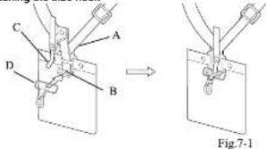
NOTICE
If side hook (D) has disengaged from hook (B), engage it.
1. insert hook (E) into side hook (C).
2. While holding hook (B) and side hook (D) in place, insert stopper (C) into the hole on hook (B).
Adjusting the harness

Fig.7-2
- As shown in the diagram, adjust the harness (A).
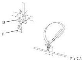
- Before starting to work, attach the side hook (D) to the suspension point (F) on the shaft tube. (Fig.7-3)
Quick-release mechanism
WARNING
- in an emergency, release the throttle trigger and shut off the engine. Support the machine with your left hand and operate the quick release mechanism. The hedge trimmer will fall, and the cutting blades can cause death or severe injury while still running.
- Be careful not to accidentally operate the red belt (Q) on the harness. The hedge trimmer will fail, and the cutting blades can cause death or severe injury while still running

Fig.7-4
In an emergency, pull upward on the red ball (GI) on the harness. This quickly releases the machine from the harness.
NOTICE
Before using the machine, check that the quick release mechanism is functioning.
Transportation
- Never transport the multi-oo with the engine running.
Inspection & Maintenance Checklist
| Checkpoints Before and after | operation | Every 30 Hours of operation | ||
| Entire Unit | Loose screws, nuts and bolts | Inspect | ○ | |
| Wear, breakage, cracks, and deformation of the cutting blades | Inspect | ○ | ||
| Grease in gearcase Reclerish grease | ○1 | |||
*1 Use / replace with Multipurpose Lithium-based grease.
Troubleshooting
This trouble planting section describes possible causes and remedies for problems you might encounter during operation of the machine. If a problem persists after you have attempted the solutions recommended in this section, contact your dealer for technical assistance. Do not attempt to disassemble the machine.
Engine does not start
| Typical cause Scoulon | |
| The stop switch is in the STOP position.The tue has deteriorated or is of poor quality.The carburetor is flooded with excess fuel.The muffler exhaust pipe sparing is blocked.The spark plug electrodes are fouled. | Set the stop switch to the START position.Use fresh tue of the correct grade.Turn the choke lever to the position opposes the START position. Pull the recoil starter cord repeatedly.Using a screwworker or other appropriate tool, remove the decorated carbon from the muffler.Clean the electrodes or replace the spark plug. |
Engine does not accelerate
| typical cause Souton | |
| The fuel has deteriorated or is of poor quality.The mutter exhaust pipe opening is blocked. | Use fresh fuel of the correct grade.Using a screwdriver or other appropriate tool, remove the decorated carbon from the mutter |
Engine stalls when the throttle trigger is released
| Typical cause Solution | |
| • The idle speed is too low. | • Adjust the idle speed with the idle-speed squater on the carburetor |
Cutting blade continues to rotate after the throttle trigger is released
| Typical cause Souton | |
| The idle speed is too high.The throttle linkage has little or no play. | Adjust the idle speed with the idle speed adjuster on the carburetorAdjust the play on the throttle linkage. |
Engine speed fluctuates
| Typical cause Souton | |
| • The fuel filter is digged. | • Clean or replace the fuel filter. |
Abnormal noise or vibration occurs
| Typical cause Solution | |
| • Cramping screws are loose | • Check the clamping screws and reighten if necessary. |
Fuel Consumption is high
| Typical cause Solution | |
| The air cleaner is cloggedCutting blades lose their cutting performance | Clean the air cleanerReplace the cutting blades |
| Sections |
| Hruncutner 3 |
| Hedge Trimmer 18 |
| Pruning Saw 30 |
| Eoiger 44 |
| Cullivestor 52 |
About This Manual
Thank you for pursuing this product. This Instruction manual describes operating procedures and precautions as well as inspection and maintenance procedures for the machine. Before using the device, read this manual carefully until you are familiar with the contents. Carefully observe all warnings and safety instructions to ensure correct operation of the machine. Doing so will ensure safe operation and optimum performance of the device. This Instruction manual covers the attachments, controls, and engine of the Multi-Combination System. Use only attachments specified by the manufacturer. Use of any other attachment can result in damage to the oculomert, possibly leading to death or severe injury. Be sure to satisfy observe the important safety information that follows each bulleted term below. Failure to follow the instructions for correct operation contained herein can result in a severe accident.
△ DANGER: Indicates that failure to follow the instructions creates an imminent hazard leading to death or severe injury. △ WARNING: Indicates that failure to follow the instructions has the potential to result in death or severe injury. △ CAUTION: Indicates that failure to follow the instructions can lead to minor injury or severe damage to the machine.
NOTE This is an auxiliary explanation that provides useful information and instructions.
Contents
| Meaning of pictograms | 52 |
| Technical Data | 58 |
| Names of Parts | 54 |
| Safety Instructions | 55 |
| Ensuing Sale Operation | 56 |
| Assembly | 57 |
| Wearing the Harness | 58 |
| Inspection and Maintenance | 59 |
| Troubleshooting | 60 |
Meaning of Pictographs
| DANCER - WARNING - CAUTION | ||
| Before using the device, read this manual carefully until you are familiar with the contents. | ||
 | Wear safety gear.1. Face shed or protective goggles2. Head protection3. Ear protection4. Heavy duty gloves5. Non slip safety shoes | |
| · Keep the working end of the machine at seat 15 m away from overhead power lines, telephone wires, and all other cables.· Do not operate the device within 15 motors of a child, animal, or bystander. | ||
| [4WWT] | ||
Technical Data - Cultivator
| Masses | Unit with specified cutting attachment, empty tank | 8.7kg |
| Cutting Attachment | Type | 2 x double blades |
| Overall length (length to gearbox) | 610mm | |
| Effective cut width | 300mm | |
| Number of times | 4 x 4 | |
| Tiling depth | 80mm | |
| External dimensions | Length (Unit & Cultivator) | 1610mm |
| Fluctuation ratio | 38:1 | |
Names of Parts
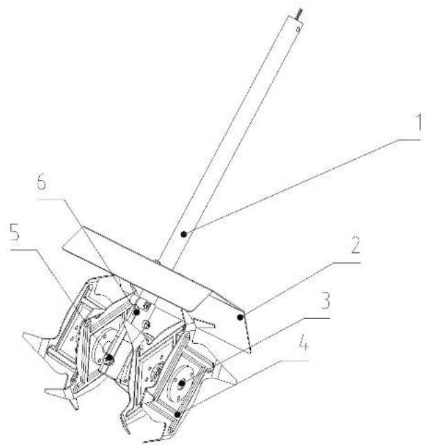
-
DRIVE SHAFT ASSEMBLY - Contains a specially designed liner and the flexible drive shaft.
-
SHIELD - Attached to defect debris away from operator and reduce accidental contact with lines.
-
FJB - Separately attached to axle ends by clews pin and spring pin. Tines bolt to hubs.
-
TINES - Identical on right and left side from operator's position. See page 12 for optional settings.
-
GREASE ACCESS BOLT Apply lithium grease with grease gun to gear housing every 30 hours of use.
-
GEAR HOUSING - Houses gears and ball bearings for driving lines.
Safety Instructions
- About This Manual CAUTION

Fig.2-1
This manual contains important safety instructions. Before using this device, read this manual carefully until you are familiar with the contents. Carefully observe all warnings and safety instructions to ensure correct operation of the machine. Dong so will ensure safe operation and optimum performance of the device.
CAUTION
This instruction manual does not cover all possible situations and conditions. Although we have taken all possible steps to ensure the safety of this device, the operator and the person performing maintenance of the device must also take all possible steps to ensure safety.
2. Recommended Uses
CAUTION
This machine should never be used for anything other than the purpose for which it has been designed.
This product has been designed for use in gardens that are already cultivated and need regular maintenance. It is not designed to create a cultivated garden from soil that has not been loosened already.
3. Safe Practices
CAUTION
Follow local noise regulations regarding the acceptable times and locations for using this device. Also observe current local safety regulations, standards, and ordinances.
4. Replacement Parts
WARNING
To maintain optimal safety and performance, use only the manufacturer's genuine parts and accessories. Do not modify the device or use it for purposes other than those specified. Failure to observe this requirement can result in severe accidents and damage to the device.
5. Operator Safety
WARNING
Do not operate this device if you..
• carne concentration due to fatigue, illness, or injury;
• are under the influence of drugs or alcohol
• are under the age of 15:
• are pregnant.
If any of the above applies, a possible lack of judgment can result in an accident.
6. Monitor the weather
WARNING

Fig.2-2
Do not operate the machine under any of the following
circumstances
- When the ground is slippery or you cannot maintain a stable posture for any reason.
- At night, in heavy fog, or at any other times where your field of vision is limited and it is difficult to gain a clear view of the working area.
- During rainstorms, thunderstorms, in strong or gaieforce winds, or in any other adverse weather in which use of this device would be unsafe.
- If the ground will become muddy become muddy during the tiling process
7. Using Safety Gear
WARNING

Fig.2-3
• Always wear proper clothing when using this device.
- Tight-litting, safe, and non-restricting clothing including a long-sleeved shirt and a pair of trousers. (Avoid wearing shorts or accessory clothing.)
- Loose filling clothing can become entangled in a tree branch or the like, posing the risk of tripping and resultant injury.
• Far protection to protect your hearing
- Face shield or protective goggles
• Heavy-duty gloves
- Non-slip safety shoes (Never operate this device while barefoot or when wearing sandals.)
• Head protection to protect your head from thrown objects, etc.
8. Basic Operations
CAUTION
- To ensure safe operation of this device, become familiar with the safety instructions and the procedure for shutting off the engine.(See Starting and Stopping the Engine.)
- In an emergency, it may be necessary to quickly release the machine from your body. Therefore, familiarize yourself with the correct use of the harness quick release mechanism. (See Wearing the Harness • Quickrelease mechanism.)
- Fuel Handling Precautions ⚠️ DANGER

Fig.2-4
- Do not operate the machine near open flame or spilled fuel.
- Do not refuel while the engine is running or while the engine is still hot after shutting off the machine.
• Do not refusal while smoking.
• Thoroughly wipe away any spilled fuel after refusing. -
Start the engine at a position at least 3 meters away from the refueling area or the fuel container. Fuel is highly inflammeable, and a line can lead to death or severe injury.
-
Exhaust Gas Precautions
DANGER

Fig.25
Do not run the engine in a room or in any confined area where exhaust emissions can accumulate. Doing so can result in an accumulation of carbon monoxide and other poisonous gases that can cause death or severe poisoning.
- Cutting Blades Precautions
△ DANGER

Fig.2-6
- Keep your hands and feet a safe distance from the cutting blades while the tiller is in operation.
- If you need to touch the tree in order to untangle vines or the like, first shut off the engine and allow the cutting blades to come to a full stop.
- Even after the cutting blades have stopped, wear heavily gloves and handle the cutting blades with care. The edges of the cutting blades are very sharp and can cause death or sovere injury.
12. The Hazard Area
WARNING
- Keep the working end of the machine away from power cables, telephone wires, and all other cables. The machine is not insulated against external electric shock. Electric shock can lead to death or severe injury.
- Do not operate the device within 15 meters of a child, animal, or bystander. Consider a 15-meter radius around the device to be a "hazard area."
- If someone approaches the hazardous area, immediately shut off the engine.
Operation of the machine can result in falling or lying objects that can lead to death or severe injury.
13. Limit your worktime
WARNING
- Rest for 10 to 20 minutes after every 30 to 40 minutes of operation. Continuing to operate the machine without a break can result in excessive fatigue. The resulting loss of attentiveness can lead to an accident or problems with your fingers or hands. If you experience any abnormal symptoms such as pain, discomfort, or paralysis of the fingers or hand, immediately stop operating the machine and seek medical attention.
14. Avoiding Electric Shock
WARNING

Fig.2-8
Never touch the spark plug cap or high-voltage wire while the device is running. Doing so can result in a high-voltage electric shock that can cause death or severe injury.
- Avoiding Burns
△CAUTION

Fig.2-9
Never touch the muffler, muffler cover, exhaust pipe, cylinder or cylinder head while the machine is running or immediately after operation, as they become very hot. Echo so can cause nums.
Ensuring Safe Operation
CAUTION
To ensure safety, strictly observe the following instructions. Failure to do so can lead to personal injury or severe damage to the machine.
1. Pre-operation inspection
Carefully inspect and perform any necessary maintenance before starting the machine. Failure to do so can lead to severe property damage or damage to the machine.
a. Tighten or replace loose or lost screws
b. Replace any damaged or worn parts.
c. Check for soiled fuel. Check the fuel tank cap and wipe off any spilled fuel.
c. Check the cutting blades for chips, cracks, deformation, and excessive wear.
For more information, see Inspection and maintenance.
2. Removing obstacles from the work area
Before starting operation, remove obstacles from the work area. Be extremely careful about obstacles that can trip the operator, such as tree roots, stumps, and holes.
3. Marking the hazard area
A circular area within a radius of 15 motors of the machine is the hazard area. When necessary, mark the rope and post a warning sign.
4. Wearing the Harness

Fig.3-1
- Put on the harness before starting to work with the machine. - Adjust the length of the harness belt so that you can hold the machine comfortably.
5. Starting the engine
- In some cases, the cutting blades can suddenly begin to run when the engine is started. Keep a safe distance from the blades when starting the engine.
- Make sure that no bystanders are within 15 meters before starting the engine.
- Place the machine on flat solid ground before starting the engine.
- Ensure that nothing is in contact with the cutting blades, including the ground.
Operation
The tiling width of the cultivator is approximately 300mm. Place cultivator in area to be tilled, hold unit firmly with left hand on front grip and right hand on rear grip and gradually engage throttle trigger. Guide the cultivator allowing the lines to pull forward; the soil hardness will control tiling speed.
The cultivator attachment is capable of tilling in the forward or reverse direction, for deep soil tilling. Till forward then lightly pull unit rearward allowing the lines to make a deeper cut into the soil. Deep soil cultivating can also be enhanced by repositioning the lines.
To raise or rotate the soil, till engine closer to the ground which will raise cultivator lines higher relative to the soil surface
△MPORTAN
Do not operate cultivator under water, the gear housing is not sealed and water will wash away lubrication damaging gears, bearings, and seals.
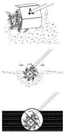
natural_image
Three-panel diagram illustrating a mechanical or robotic system with a moving cart, a gear mechanism, and a circular component (no text or symbols)Assembly
Attaching The Tools To The Drive Shaft Assembly
- Rest the power unit/shelf assembly on a flat firm surface.
- Ensure that the clamping wing nut (2) is loose, pull out locator pin (1).
- Carefully fit attachment drive shaft assembly (5) into coupler (3).
- After the attachment drive shaft is in the coupler, release the locator pin (1).
- Turn the attachment drive shaft until the locator pin engages with the locating hole (4) in the drive
- shaft, when this has happened it will not be possible to twist the drive shaft.
- Secure the drive shaft by tightening the clamping wing nut (2).

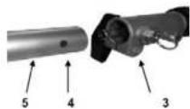


Transportation
- Never transport the multi-tool with the engine running.
Wearing the Harness
NOTE
The harness has a quick-release mechanism that allows you to immediately release the machine from the harness in an emergency.
Attaching the side hook
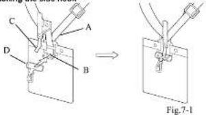
NOTE
It side hook (D) has disengaged from hook (B), engage it.
-
Insert hook (B) into side hook (D).
-
While holding hook (B) and side hook (D) in place, insert slopper (C) into the hole on hook (B).
Adjusting the harness

Fig.7-2
- As shown in the diagram, adjust the harness (A).
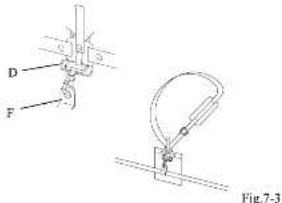
- Before starting to work, attach the side hook (D) to the suspens on point (F) on the shaft tube. (Fig.7-3)
Quick-release mechanism
WARNING
- In an emergency, releases the throttle trigger and shut off the engine. Support the machine with your left hand and operate the quick release mechanism. The hedge trimmer will fall, and the cutting blades can cause death or severe injury while still running.
- Be careful not to accidentally operate the red belt (GI) on the
harness. The hedge limmer will fall, and the cutting blades can cause death or severe injury while still running.
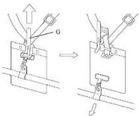
Fig.7-4
In an emergency, pull upward on the rod bolt (GI) on the harness. This quickly releases the machine from the harness.
NOTE
Before using the machine, check that the quick release mechanism is functioning.
Inspection & Maintenance Checklist
| Checkpoints Before and after | operation | Every 30 Hours of operation | ||
| Entire Unit | Loose screws, nuts and bolts | Inspect | ○ | |
| Wear, breakage, cracks, and deformation of the cutting blades | Inspect | ○ | ||
| Grause in gearcase Reorench groove | ○* | |||
*1 Use / replace with Multipurpose Lithium-based grease.
Troubleshooting
This troubleshooting section describes possible causes and remedies for problems you might encounter during operation of the machine. If a problem persists after you have attempted the solutions recommended in this section, contact your dealer for technical assistance. Do not attempt to disassemble the machine.
Engine does not start
| Typical cause Solution | |
| The stop switch is in the STOP position.The fuel has deteriorated or is of poor quality.The carburetor is flooded with excess fuel.The muffler exhaust pipe opening is blocked.The spark plug electrodes are fouled. | Set the stop switch to the START1 position.Use their fuel of the correct grade.Turn the choke lever to the position opposes the START position. Pull the recoil starter cord repeatedly.Using a screwdriver or other appropriate tool, remove the deposited carbon from the muffler.Clean the electrodes or replace the spark plug. |
Engine does not accelerate
| Typical cause Solution | |
| The fuel has deteriorated or is of poor quality.The muffler exhaust pipe opening is blocked. | Use fresh fuel of the correct grade.Using a screwdriver or other appropriate tool, remove the deposited carbon from the muffler |
Engine stalls when the throttle trigger is released
| Typical cause Solution | |
| • The idle speed is too low. • Adjust the idle speed with the idle-speed soluster on the carburetor | |
The cutting lines continues to run though the throttle trigger has been released.
| Typical cause Solution | |
| The idle speed is too high.The throttle linkage has little or no play. | Adjust the idle speed with the idle speed adjuster on the carburetor.Adjust the play on the throttle linkage. |
Engine speed fluctuates
| Typical cause Solution | |
| • The fuel filter is clogged. • Clean or replace the fuel filter. |
Abnormal noise or vibration occurs
| Typical cause Solution | |
| • Clamping screws are loose • Check the clamping screws and relighten if necessary. | |
Fuel Consumption is high
| Typical cause Solution | |
| The air cleaner is clogged.Cutting lines lose their performance | Clean the air cleanerReplace the cutting lines |
Morrison, a division of Masport Limited
1-37 Mt Wellington Highway, Panmure
Auckland 1060
New Zealand
P: 0800 627 767
Masport Australia Pty Limited
27 Commercial Drive
Dandenong South, VIC 3175
Australia
P: 1300 366 225