
DK 4360 - Range hood AEG-ELECTROLUX - Free user manual and instructions
Find the device manual for free DK 4360 AEG-ELECTROLUX in PDF.
| Brand | AEG-Electrolux |
| Model | DK 4360 |
| Product type | Extractor hood (with recirculation option) |
| Dimensions (external extraction) | Height: 62.2 - 115.2 cm, Width: 59.8 cm, Depth: 45 cm |
| Dimensions (recirculation) | Height: 69.9 - 115.2 cm, Width: 59.8 cm, Depth: 45 cm |
| Power supply | 220 - 240 V, 50/60 Hz (not specified but standard) |
| Cable length | 150 cm |
| Number of speeds | 3 mechanical speeds |
| Lighting | Yes, replaceable bulb |
| Grease filter | Washable metal filter (dishwasher or hand wash) |
| Activated carbon filter | Optional (type 20), cleanable and reusable |
| Minimum safety distance | 50 cm for electric cookers, 65 cm for gas or mixed |
| Extraction diameter | 150 mm (reduction 150/125 mm possible) |
| Accessories supplied | TORX key, reduction sleeve, deflector, chimney bracket, wall plugs, screws, washers |
| Installation | By a qualified professional |
| Regular maintenance | Clean grease filter every 4 weeks, carbon filter every 2 months |
| Energy consumption | Not specified |
| Energy efficiency class | Not specified |
| Noise level | Not specified |
| Warranty | Not specified in the manual |
Frequently Asked Questions - DK 4360 AEG-ELECTROLUX
User questions about DK 4360 AEG-ELECTROLUX
0 question about this device. Answer the ones you know or ask your own.
Ask a new question about this device
Download the instructions for your Range hood in PDF format for free! Find your manual DK 4360 - AEG-ELECTROLUX and take your electronic device back in hand. On this page are published all the documents necessary for the use of your device. DK 4360 by AEG-ELECTROLUX.
USER MANUAL DK 4360 AEG-ELECTROLUX
Chere cliente, cher client,
Description of the Appliance 54
Extraction mode 54
Recirculation mode 54
Control Panel 55
Maintenance and Care 56
Metal grease filter 56
Charcoal filter 57
Changing the light bulbs 58
Cleaning the hood 58
Special accessories 58
Something Not Working 59
Technical assistance service 60
Service and Spare Parts 60
Customer Care Department 61
Technical Details 61
Mounting accessories included 61
Electrical connection 62
Safety warnings for the electrician 62
Before beginning installation 63
Installation 64
Safety warnings
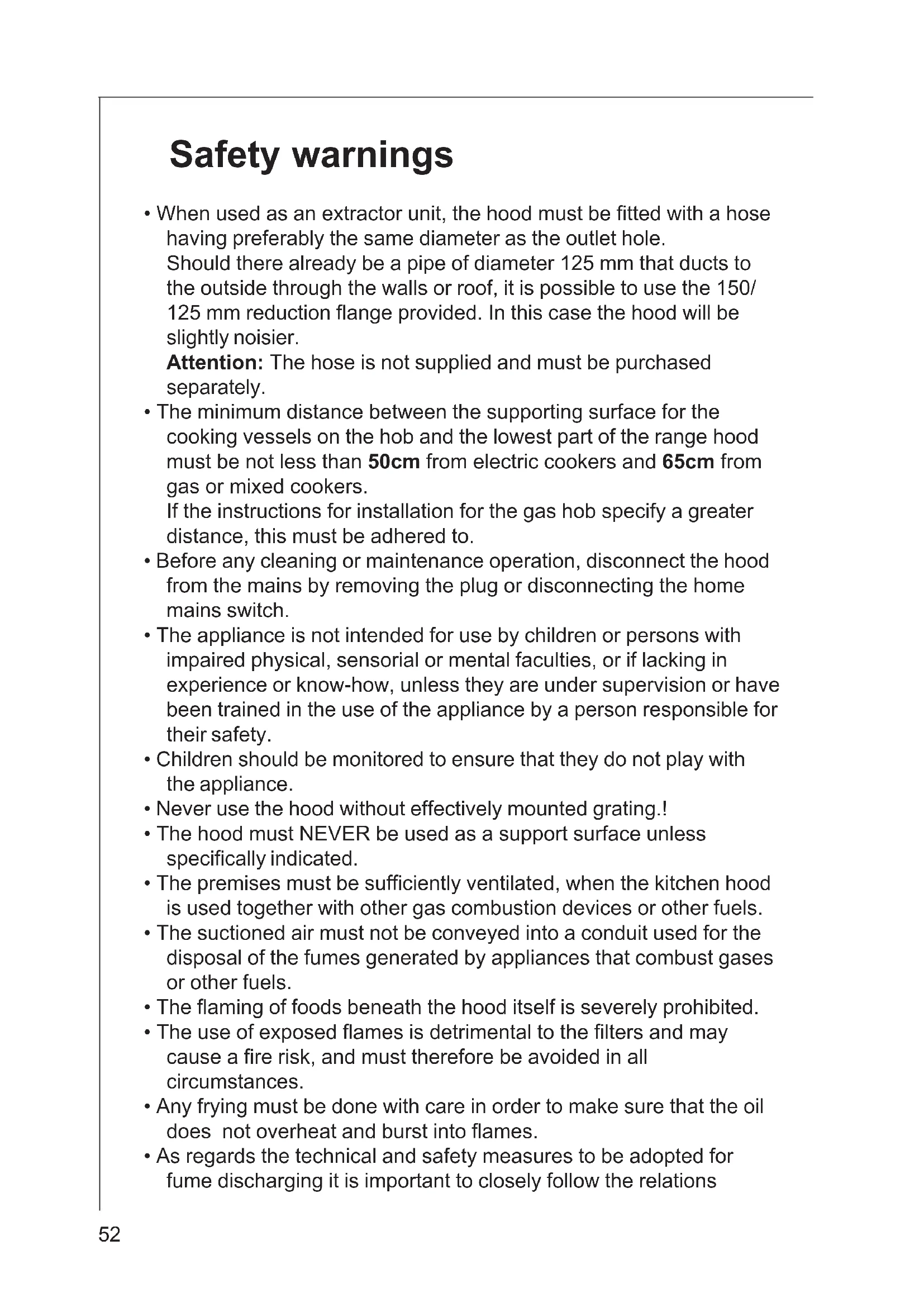
- When used as an extractor unit, the hood must be fitted with a hose having preferably the same diameter as the outlet hole.
Should there already be a pipe of diameter 125mm that ducts to the outside through the walls or roof, it is possible to use the 150/125 mm reduction flange provided. In this case the hood will be slightly noisier.
Attention: The hose is not supplied and must be purchased separately.
- The minimum distance between the supporting surface for the cooking vessels on the hob and the lowest part of the range hood must be not less than 50cm from electric cookers and 65cm from gas or mixed cookers.
If the instructions for installation for the gas hob specify a greater distance, this must be adhered to. - Before any cleaning or maintenance operation, disconnect the hood from the mains by removing the plug or disconnecting the home mains switch.
- The appliance is not intended for use by children or persons with impaired physical, sensorial or mental faculties, or if lacking in experience or know-how, unless they are under supervision or have been trained in the use of the appliance by a person responsible for their safety.
- Children should be monitored to ensure that they do not play with the appliance.
- Never use the hood without effectively mounted grating!.
- The hood must NEVER be used as a support surface unless specifically indicated.
- The premises must be sufficiently ventilated, when the kitchen hood is used together with other gas combustion devices or other fuels.
- The suctioned air must not be conveyed into a conduit used for the disposal of the fumes generated by appliances that combust gases or other fuels.
- The flaming of foods beneath the hood itself is severely prohibited.
- The use of exposed flames is detrimental to the filters and may cause a fire risk, and must therefore be avoided in all circumstances.
- Any frying must be done with care in order to make sure that the oil does not overheat and burst into flames.
- As regards the technical and safety measures to be adopted for fume discharging it is important to closely follow the relations
provided by the competent authorities.
- The hood must be regularly cleaned on both the inside and outside (AT LEAST ONCE A MONTH, it is in any event necessary to proceed in accordance with the maintenance instructions provided in this manual)..
- Failure to follow the instructions as concerns hood and filter cleaning will lead to the risk of fires.
- Do not use or leave the hood without the lamp correctly mounted because of the possible risk of electric shocks.
- We decline any responsibility for any problems, damage or fires caused to the appliance as the result of the non-observation of the instructions included in this manual.
This appliance is marked according to the European directive 2002/96/ EC on Waste Electrical and Electronic Equipment (WEEE).
By ensuring this product is disposed of correctly, you will help prevent potential negative consequences for the environment and human health, which could otherwise be caused by inappropriate waste handling of this product.
The symbol on the product, or on the documents accompanying the product, indicates that this appliance may not be treated as household waste. Instead it shall be handed over to the applicable collection point for the recycling of electrical and electronic equipment. Disposal must be carried out in accordance with local environmental regulations for waste disposal.
For more detailed information about treatment, recovery and recycling of this product, please contact your local city office, your household waste disposal service or the shop where you purchased the product.
Description of the Appliance
- The cooker hood is designed to extract unpleasant odours from the kitchen, it will not extract steam.
- The hood is supplied as an extractor unit and can also be used with a recirculation mode by fitting a charcoal filter.
Extraction mode
- In this mode fumes are extracted to the outside via a hose connected to the coupling ring. Fig. 1
- In order to obtain the best performance the hose should have a diameter equal to the outlet hole.
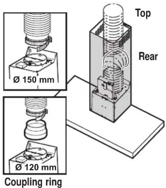
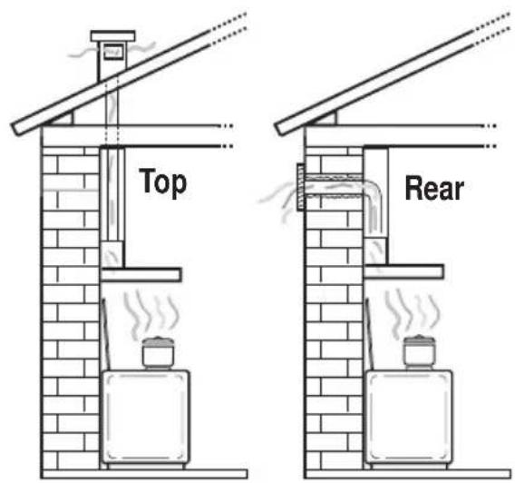
Fig. 1
Recirculation mode
The air is filtered through a charcoal filter and returned to the kitchen. Fig. 2
- You will need an original charcoal filter for the recirculation mode. (See Special Accessories).
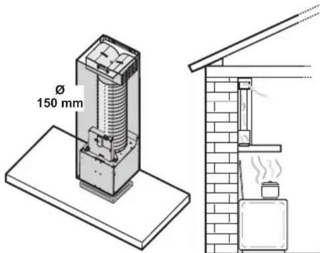
Fig. 2
Control Panel
- Best results are obtained by using a low speed for normal conditions and a high speed when odours are more concentrated. Turn the hood on a few minutes before you start cooking. The hood should be left on after cooking for about 15 minutes or until all the odours have disappeared. The control switches are located on the unit's front panel:
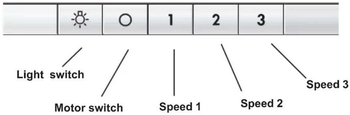
- the light switch switches the hood lamp on and off
- the motor switch switches the motor off
- Speed 1: Speed 1 push-button
- Speed 2: Speed 2 push-button
- Speed 3: Speed 3 push-button
Maintenance and Care
Warning! Before performing any maintenance operation, isolate the hood from the electrical supply by switching off at the connector and removing the connector fuse.
Or if the appliance has been connected through a plug and socket, then the plug must be removed from the socket.
Metal grease filter
- The purpose of the grease filters is to absorb grease particles which form during cooking and it must always be used, either in the external extraction or internal re-circulation function.
Attention: the metal grease filters must be removed and washed, either by hand or in the dishwasher, every four weeks.
Removing the metal grease filters
- Push it towards the back of the unit and then pull it down and out.
Fig. 3.
Hand washing
Soak grease filters for about one hour in hot water with a grease- loosening cleaner, then rinse off thoroughly with hot water. Repeat the process if necessary. Refit the grease filters when they are dry.
Dishwasher
Place grease filters in the dishwasher. Select most powerful washing programme and highest temperature, at least 65^ .
Repeat the process. Refit the grease filters when they are dry.
When washing the metal grease filter in the dishwasher a slight discolouration of the filter can occur, this does not have any impact on its performance.
- Clean the inner housing using a hand hot solution only (never use caustic detergents, abrasive powders or brushes).
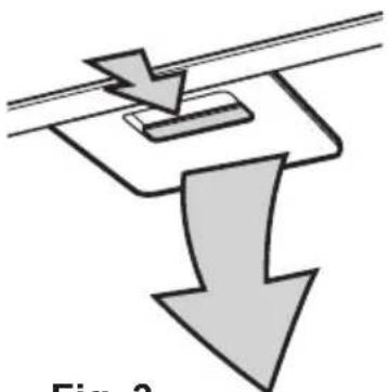
Fig. 3
Charcoal filter
- The charcoal filter should only be used if you want to use the hood in recirculation mode.
- Cleaning/replacing the carbon filter
Unlike other carbon filters, the LONGLIFE carbon filter can be cleaned and reactivated. At normal use the filter should be cleaned every second month (when using the hood 2,5 hours per day, in avarage). The best way to clean the filter is in the dishwasher. Use normal detergent and choose the highest temperature (65^) .
Wash the filter separately so that no food parts gets stuck on the filter and later causes bad odours. To reactivate the carbon, the filter should be dried in an oven for 10 minutes with a temperature of maximum 100^ C.
After approximately three years of use, the carbon filter should be replaced with a new one, as the odour reduction capacity will be reduced.
Fitting
Remove the grease filters. Remove the frame i which supports the filter h by turning 90^ the two knobs g.
Insert the charcoal filter inside the frame and put all parts back in their place. Refit the grease filters. Fig. 4.
- To remove proceed in the reverse order.
- Always specify the hood model code number and serial number when ordering replacement filters. This information is shown on the rating plate located on the inside of the unit.
- The charcoal filter can be ordered from your local Service Force Centre.
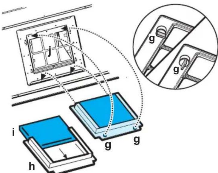
Fig. 4

Warning
-
Failure to observe the instructions on cleaning the unit and changing the filters will cause a fire hazard. You are therefore strongly recommended to follow these instructions.
-
The manufacturer declines all responsibility for any damage to the motor or any fire damage linked to inappropriate maintenance or failure to observe the above safety recommendations.
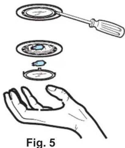
Changing the light bulbs
- Disconnect the cooker hood from the mains supply.
- Prior to touching the light bulbs ensure they are cooled down.
- Extract the lamp cover by using a small flat screwdriver or similar tool as a lever.
- Replace the old bulb with a new one of the same type.
- Refit the lamp cover.
- If the light does not come on, make sure the bulb has been inserted in correctly before contacting your local Service Force Centre.
Cleaning the hood
- Clean the outside of the hood using a damp cloth and a solution of water and mild washing up liquid.
- Never use corrosive, abrasive or flammable cleaning products or products containing bleach.
- Never insert pointed objects in the motor's protective grid.
- Only ever clean the switch panel and filter grill using a damp cloth and mild washing up liquid.
- Clean all the plastic parts with a soft cloth soaked in warm water and neutral soap.
- It is extremely important to clean the unit and change the filters at the recommended intervals. Failure to do so will cause grease deposits to build up that could constitute a fire hazard.
Special accessories
Charcoal filter TYPE 20
Something Not Working
If your appliance fails to work properly please carry out the following checks.
| Symptom Solution | |
| The cooker hood Check will not start... the electric | that: The hood is connected to city supply. Check that a fan speed has been selected |
| The cooker hood Check is not working high enough | that: The fan speed is set gh for the task. The grease filters are clean. The kitchen is adequately vented to allow the entry of fresh air. If set up for recirculation, check that the charcoal filter is still effective. If set up for extraction, check that the ducting and outlets are not blocked. |
| The cooker hood has The safety cut-out device has been switched off tripped. during operation... Turn off the hob and then wait for the device to reset. If the hood has been installed below the heights indicated in the installation instructions the motor will cut-out frequently which will damage the hood. |
If after all these checks, the problem persists, contact your local
Service Centre, quoting the model and serial number.
Please note that it will be necessary to provide proof of purchase for any in-guarantee service calls.
In-guarantee customers should ensure that the above checks have been made as the engineer will make a charge if the fault is not a mechanical or electrical breakdown.
Technical assistance service (not for UK)
You are welcome to telephone our technical assistance service (see list of technical assistance centres) whenever you need information or in the unlikely event of a fault.
For service in Australia call 1300 650 020.
When calling, please be ready to specify:
This information is shown on the registration plate inside the unit behind the grease filter.
We reserve the right to change specifications and colours as a result of our policy of continuing technological development.
Service and Spare Parts
In the event of your appliance requiring service, or if you wish to purchase spare parts, contact your local Service Force Centre by telephoning: 08705 929 929
Your call will be automatically routed to the Service Centre covering your post code area. For the address of your local Service Force Centre and further information about Service Force, please visit the website at www.serviceforce.co.uk
Please ensure that you have read the section "What to do if..." as the engineer will make a charge if the fault is not a mechanical or electrical breakdown even the appliance is under warranty. Please note that proof of purchase is required for in-guarantee service calls.
Help us to help you
Please determine your type of enquiry before writing or telephoning.
When you contact us we need to know:
- Your name • Clear and concise details of the fault
- Address and post code • Name and model of the appliance*
-
Telephone number • E number*
-
Serial number*
-
This information can be found on the rating plate, which can be seen when the grease filters are removed.
If you require Customer Service in the Republic of Ireland please contact us at the address below:
AEG
Electrolux Group (Ire) Ltd
Long Mile Road
Dublin 12
Republic of Ireland
Tel: +353 (0) 14090751
Email: service.eid@electrolux.ie
CUSTOMER CARE DEPARTMENT
For general enquiries concerning your AEG appliance or for further information on AEG products, please contact our Customer Care Department by letter or telephone at the address below or visit our website at www.aeg.co.uk
Customer Services Department
Major Appliances
AEGElectrolux
Addington Way
Luton
Bedfordshire
LU49QQ
08705350350*
- calls to this number may be recorded for training purposes
Technical Details
DK 4360 DK 4390
Dimensions (in cm):
Height (Extract. mode): 62,2-115,2 62,2-115,2
Height (Recirc. mode): 69,9-115,2 69,9-115,2
Width: 59,8 89,8
Depth: 45 45
Max. absorb. power: 160 W 160 W
Motor: 120 W 120 W
Lighting: 2 × 20 ~W (G4) 2 × 20 ~W (G4)
Length of the cable: 150 cm 150 cm
Electrical connection: 220-240 V 220-240 V
Fuse rating: 5At 5At
Mounting accessories included
1 allen wrench (for TORX screws).
1 deflector ,
1 reduction flange 0 125-120 mm ,
1 chimney support,
6 wood-screws 5 × 45 ~mm (for wall mounting),
6 Wall dowels 0.8mm (for wall mounting),
2 washers
2 screws 2,9 × 6,5 (2 to fix the upper chimney)
2 metal screws 3 × 9 (to fix the deflector).
Electrical connection
Safety warnings for the electrician
Safety warnings for the electrician
The mains power supply must correspond to the rating indicated on the plate situated inside the hood. If provided with a plug connect the hood to a socket in compliance with current regulations and positioned in an accessible area. If it not fitted with a plug (direct mains connection) or if the plug is not located in an accessible area apply a bi-polar switch in accordance with standards which assures the complete disconnection of the mains under conditions relating to overcurrent category III, in accordance with installation instructions.
IMPORTANT: Before re-connecting the hood circuit to the mains supply and checking the efficient function, always check that the mains cable is correctly assembled.
Before beginning installation
- In addition check whether near the installation area of the hood (in the area accessible also with the hood mounted) an electric connection to the mains is available and if it is possible to connect a fumes discharge device to the outside (Extraction mode only).
- Warning! Do not connect the appliance to the mains until the installation is fully complete.
Install the electronic box with 2 screws (a-b-c). Fig. 6
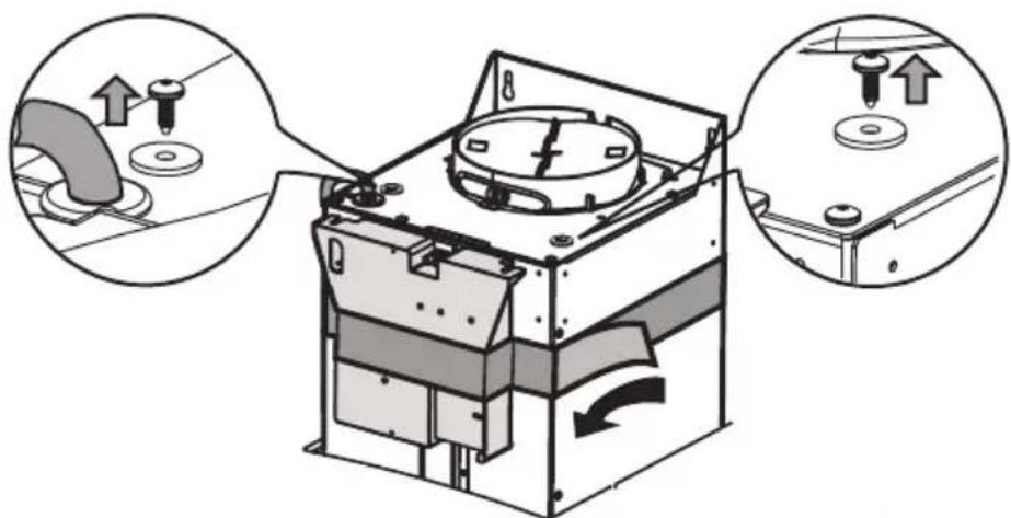
Fig. 6a
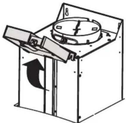
Fig. 6b
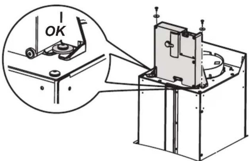
Fig. 6c
Installation
- Remove the grease filters.
- Drawing a line on the wall with a pencil up to the ceiling, corresponding to the centre line, will make the installation operations easier. Fig. 7
- Apply the perforation diagram to the wall: the vertical centre line printed on the perforation diagram should correspond to the centre line drawn on the wall. In addition, the lower edge of the perforation diagram corresponds to the lower edge of the hood. Fig. 8
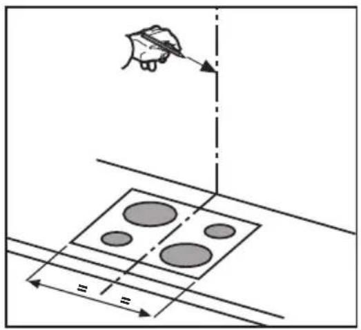
Fig. 7
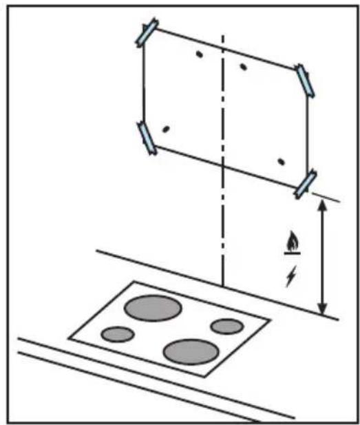
Fig. 8
- Make holes as indicated on the template, insert the wall dowels and screw 2 screws into the upper holes, leaving a space of about 1cm between the head of the screw and the wall. Fig9a-b
Note: Always make the holes indicated on the template. The upper 2 are for hooking the hood up while the lower holes (generally 2 lateral) are for the definitive and safety fixing.
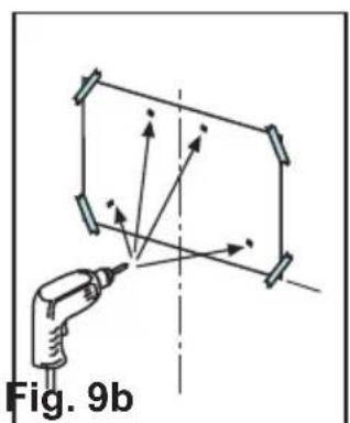
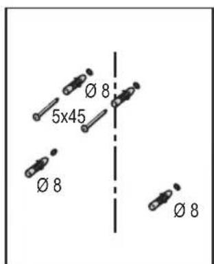
Fig. 9a Fig. 9b
- Apply flues support bracket to the wall touching the ceiling. Use the flues support bracket as a perforation diagram (the small slot in the support must coincide with the line previously drawn on the wall, if present), and mark two holes with a pencil. Make the holes and insert 2 dowels.
Fix the flues support bracket to the wall with 2 screws. Fig.10
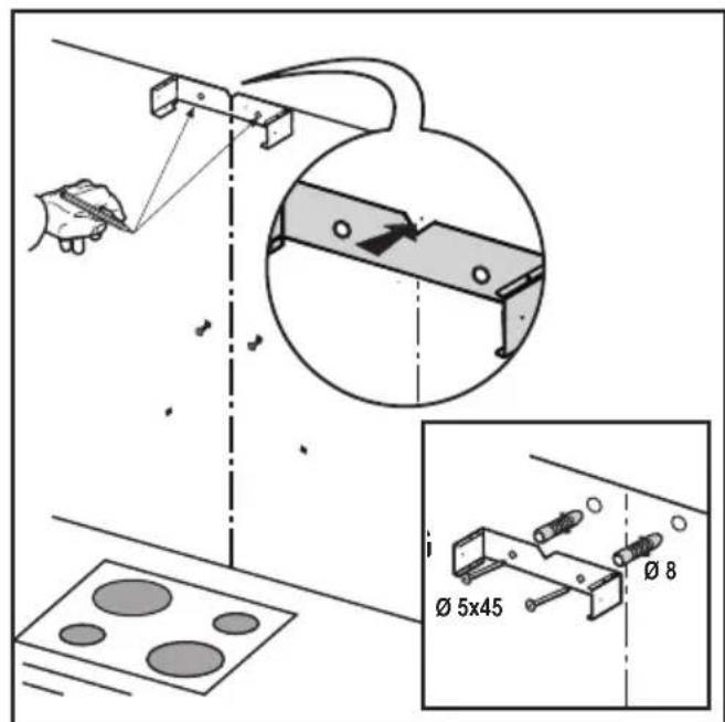
Fig. 10
- Hang the hood to the 2 upper screws.
- Introduce and screw the screws (and washers) up into the holes for the definitive fixing (COMPULSORY!!). Then, having checked the setting of the hood, TIGHTEN ALL THE upper and lower SCREWS. Fig. 11
Note: the lower fixing points are visible removing the grease filters and they are at the sides of the hood
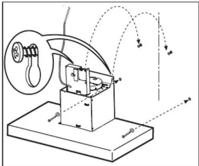
Fig. 11
- Connect a tube (tube and bands for fixing not supplied, to be purchased) for discharging the fumes to the connection ring placed over the aspiration motor unit.
The other end of the tube should be connected to a device for expelling fumes on the outside of the hood in the aspiration version.
Fig. 12a-b
If you want to use the filtering version, fix deflector to flues support bracket and connect the other end of the tube to the connection ring placed on deflector. Fig. 12c
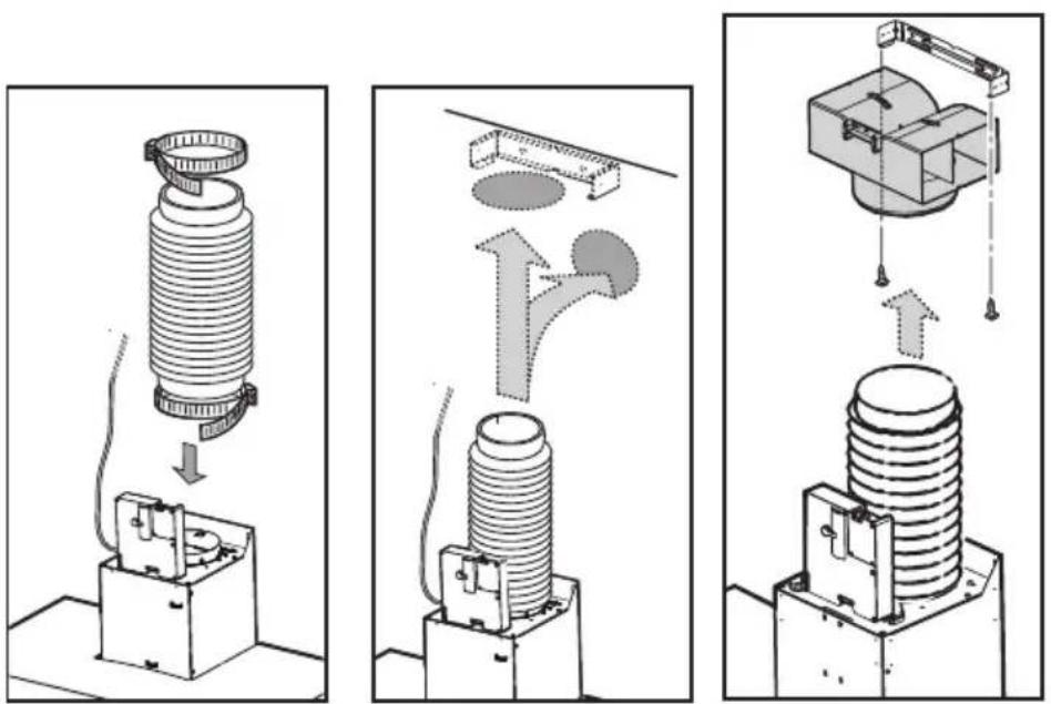
Fig. 12a Fig. 12b Fig. 12c
- Connect the electricity.
- Slide the lower section of the flue down to cover the aspiration set until inserting it completely into the apposite housing over the hood. Fig. 13a
- Raise the upper flue and fix it above with 2 screws to flues support bracket.
Fig.13b
- Refit the grease filter.
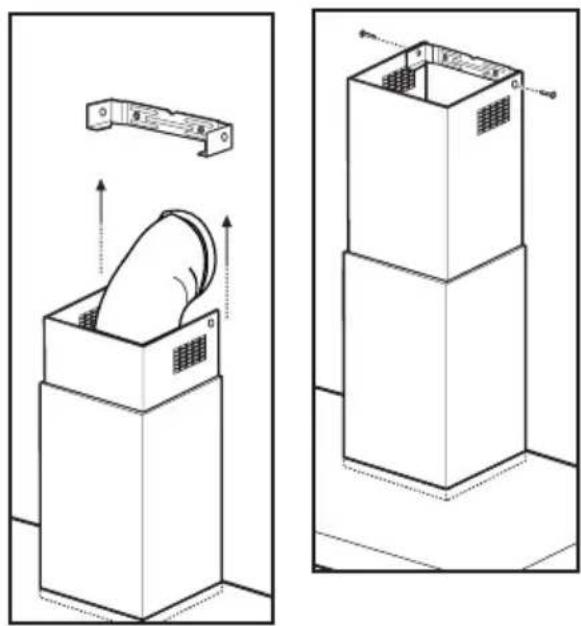
Fig. 13a Fig. 13b


- Chere cliente, cher client,
- Safety warnings
- Description of the Appliance
- Extraction mode
- Recirculation mode
- Control Panel
- Maintenance and Care
- Metal grease filter
- Removing the metal grease filters
- Hand washing
- Dishwasher
- Charcoal filter
- - Cleaning/replacing the carbon filter
- Fitting
- Warning
- Changing the light bulbs
- Cleaning the hood
- Special accessories
- Something Not Working
- Technical assistance service (not for UK)
- Service and Spare Parts
- Help us to help you
- CUSTOMER CARE DEPARTMENT
- Technical Details
- Mounting accessories included
- Electrical connection
- Safety warnings for the electrician
- Before beginning installation
- Installation
Brand : AEG-ELECTROLUX
Model : DK 4360
Category : Range hood