Revmaster Classic - Exercise bike LeMond Fitness - Free user manual and instructions
Find the device manual for free Revmaster Classic LeMond Fitness in PDF.

| Product Type | Indoor Cycle |
| Brand | LeMond Fitness |
| Model | Revmaster Classic |
| Dimensions (L x W x H) | 105 x 57 x 97 cm |
| Weight | 53 kg |
| Power Source | None (manual resistance) |
| Resistance | Leather pad friction system with tension knob |
| Emergency Brake | Red lever |
| Flywheel | Chrome precision-machined flywheel (21.3 kg) |
| Frame | Ultra-durable X-Style design, stainless steel |
| Handlebar | Height and tilt adjustable, rubber coating |
| Seat | Height and fore/aft adjustable |
| Pedals | With adjustable toe cages |
| Cranks | Cast stainless steel, 170 mm |
| Belt | Non-slip, Kevlar-reinforced |
| Transport Wheels | Yes, extra-wide |
| Frame Warranty | 5 years |
| Parts Warranty | 1 year (bearings, bushings), 3 years (cranks, flywheel, handlebar, seat post), 90 days (wear parts) |
| Maintenance | Daily cleaning, weekly brake pad inspection, monthly belt inspection |
| Safety | No freewheel, emergency stop, do not use without supervision in commercial use |
| Repairability | Spare parts available, user-serviceable |
| Usage | Individual or group cardiovascular training |
Frequently Asked Questions - Revmaster Classic LeMond Fitness
User questions about Revmaster Classic LeMond Fitness
0 question about this device. Answer the ones you know or ask your own.
Ask a new question about this device
Download the instructions for your Exercise bike in PDF format for free! Find your manual Revmaster Classic - LeMond Fitness and take your electronic device back in hand. On this page are published all the documents necessary for the use of your device. Revmaster Classic by LeMond Fitness.
USER MANUAL Revmaster Classic LeMond Fitness
17820 Woodinville-Redmond Rd.
Building B, Suite 888
Tel.: (425) 482-6773
Fax: (425) 482-6724
Visit our website at
www.LeMondfitness.com
P/N 300202
© 2002 LeMond Fitness Inc. LeMond and RevMaster are registered trademarks.
WARRANTY
This is to certify that the LeMond® RevMaster™ exercise bike is warranted by LeMond Fitness Inc. to be free of all defects in materials and workmanship. This warranty does not apply to any defect caused by negligence, misuse, accident, alteration, improper maintenance, or an "act of God."
The LeMond RevMaster carries a five-year frame warranty, a one-year warranty on bottom bracket bearings, pillow block bearings, tension knob assembly, a three-year warranty on cranks, bottom bracket spindle, flywheel, handlebar, seat post, handlebar post, and a 90 day warranty on wearables such as seat, grip, handles, and brake pad. Contact our Customer Service Department to report any problems. When calling, please be prepared to provide the customer service representative with the following information:
- Your name, customer number, shipping address, and telephone number
T h e s c r i a l n u m b c r Y o u r b i l l i n g a d d r e
This information will ensure that you are the only one ordering parts under your warranty protection. If warranty replacement parts are shipped to you, you may be required to return the inoperable part. To facilitate this process, the following policy has been established:
- P l e a s e c a l l o u r C goods authorization prior to shipment.
L e M o n d F i t n e s s w parts ordered for a machine that is less than 45 days old. - Y o u a r e r c s p o n s i b machines that are more than 45 days old. You will not be responsible for the return shipment of the inoperable parts.
- S o m e i n o p e r a b l e V Customer Service Department. We will pay the shipping cost for the inoperable warranty parts. Detailed instructions are included with each warranty replacement part.
LeMond Fitness Inc. neither makes, assumes nor authorizes any representative or other person to make or assume for us, any other warranty whatsoever, whether expressed or implied, in connection with the sale, service, or shipment of our products. We reserve the right to make changes and improvements in our products without incurring any obligation to similarly alter products previously purchased. In order to maintain your product warranty and to ensure the safe and efficient operation of your machine, only authorized replacement parts can be used. This warranty is void if parts other than those provided by LeMond Fitness are used.
PREFACE
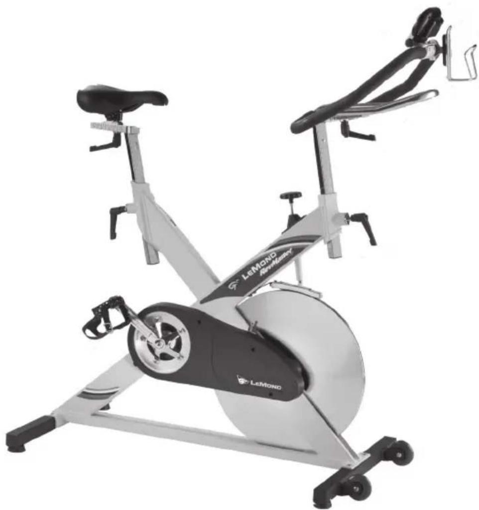
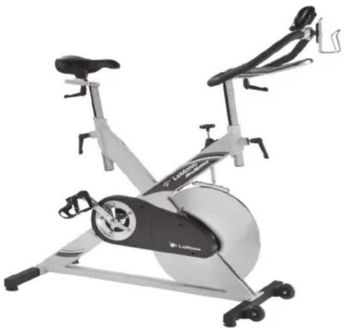
The LeMond® RevMaster® bike is a safe, functional, and effective exercise modality for developing aerobic fitness and increasing the strength of the major muscle groups of the lower body. It is designed for use by individuals of all ages and fitness levels. Your purchase of this bike is a positive affirmation of your commitment to use the best available methods for enhancing your functional fitness capabilities. In order to derive optimal benefits from your equipment, you should read this manual thoroughly and adhere closely to the instructions.
WHAT IS IN THIS MANUAL?
Following the information on safety guidelines and an explanation of installation procedures, this manual will provide general exercise guidelines and explain how the LeMond RevMaster exercise bike works. Detailed instructions of parts removal and replacement are then followed by exploded diagrams of the bike components.
The LeMond RevMaster is a revolutionary new group exercise stationary cycle from LeMond Fitness Inc. that delivers an extraordinary workout. It has been designed to be stronger, more stable, feel more comfortable, be easier to adjust, and have a more durable crank system then conventional group exercise bikes.
The LeMond RevMaster bike was designed by Paul Swift under the direction of Greg LeMond. LeMond is the first American to win the Tour de France. A cyclist who has won the world's most challenging races, Greg LeMond has also revolutionized the sport by introducing cutting edge technology that is commonplace today. Paul Swift is a 15-year member of the USA cycling team, eight-time national champion and 1998 Goodwill Games Gold Medalist.
CONTENTS
SAFETYGUIDELINES 1
INSTALLATION INSTRUCTIONS 3
Delivery 3
Your first workout on the LeMond® RevMaster®
Exercise Bike 8
Seat Adjustment 8
Handlebar Adjustment 8
Pedal Strap Adjustment 9
GENERAL EXERCISE GUIDELINES 10
Setting a goal 10
Flexibility Training 10
Exercise Principles 11
MAINTENANCE INSTRUCTIONS 12
Helpful Hints 12
Tool List. 12
Preventive Maintenance 12
Daily 13
Weekly. 13
Monthly 13
TROUBLESHOOTING 14
Symptom: Adjustment Handles do not engage 14
Symptom: Handlebar/Seat post will not slide up or down 14
Symptom: Pedals are slipping 14
Symptom: Pedals do not rotate 14
PARTS REMOVAL AND REPLACEMENT 15
Adjustment Handles 15
Belt 16
Bottom Bracket Bearings 16
Brake Pad Assembly 18
CONTENTS
Covers 19
Flywheel/Pillow Block Bearings 19
Handlebar 20
Handlebar Post 20
Pedals 21
Pedal Crank Arms 21
Seat 22
Seat Slider 22
Seat Post 23
Tension Knob Assembly 23
FIGURES 24
Figure 1: Final Assembly 24
Figure 2: Crank Assembly 25
Figure 3: Flywheel Assembly 26
Figure 4: Belt Tension 27
Figure 5: Front Base Assembly 28
Figure 6: Rear base Assembly 29
Figure 7: Brake Tension Knob Assembly 30
Figure 8: Brake Pad Assembly 31
Figure 9: V-Plunger & Plug 32
SPECIFICATIONS 33
LIST OF TABLES
Table 1. Dimensions and Specifications for the
LeMondRevMasterExercise Bike. 3
SAFETY GUIDELINES
IMPORTANT SAFETY INSTRUCTIONS

This symbol appearing throughout this manual means Attention! Be Alert! Your safety is involved.
The following definition applies to the word "WARNING" found throughout this manual:
WARNING- Used to call attention to POTENTIAL hazards that could result in personal injury or loss of life.
READ ALL INSTRUCTIONS BEFORE USING THIS EXERCISE EQUIPMENT.
- Close supervision is necessary whenever the equipment is used by, or near children, invalids, or disabled persons. A serious injury could result from a child's fascination with the moving components of the exercise system.
- Keep your hands away from all moving parts and keep your feet on the pedals while exercising. Do not remove your feet from the RevMastebike pedals while they are in motion.
- Use this equipment only for its intended use as described in this Manual. Do not attempt to ride this bike at high pedal speeds or in a standing position until you practiced and are comfortable riding at slower pedal speeds.
- Rotate the tension knob clockwise to apply resistance to the flywheel prior to standing on the pedals.
- Do not dismount the RevMaster bike until both of the pedals and the flywheel are at a complete stop.
- Never turn the pedal crank arms by hand. Do not expose your hands or your arms to the drive mechanism as possible injury could occur.
SAFETY GUIDELINES
- Do not perform push-up type movements on the handlebars.
- After exercising, turn the tension knob clockwise or push down on the tension knob to slow the flywheel down so that the pedals do not rotate freely and possibly hurt somebody.
- Never drop or insert any object into any opening on the exercise equipment.
The safety level given by the design of this equipment can only be maintained when the equipment is regularly examined for damage and wear. Inoperable components should be replaced immediately or the equipment should be put out of use until it is repaired.
Failure to follow all guidelines may compromise the effectiveness of the exercise experience, expose yourself (and possibly others) to injury, and reduce the longevity of the equipment.
SAVE THESE INSTRUCTIONS
Your comments and suggestions are welcome. Congratulations, and thank you for buying the RevMaster!
Your serial number(s):
YourLeMondFitness
Dealer:
Phone:
INSTALLATION INSTRUCTIONS
Before leaving the manufacturing facility, your LeMond RevMaster exercise bike was thoroughly inspected and tested for proper operation. To minimize shipping damage, careful attention was given to making your bike ready for shipment. The dimensions of the machine are listed in Table 1.
Table 1. Dimensions for the LeMond® RevMaster®Bike
| Physical Dimensions: |
| Length 41.50 inches (105 cm) |
| Width 22.25 inches (57 cm) |
| Height 38.00 inches (97 cm) |
| Weight 116pounds (53 kg) |
DELIVERY
Your LeMond RevMaster will arrive packed in 1 carton. Upon arrival fully inspect the carton for damage. Point out any damage to the delivery person and have the delivery person record the damage on the delivery paperwork. Contact the Customer Service Department at (425) 482-6773 to report any damage.
Please follow these detailed instructions and you will find that your bike can be unpacked and assembled with ease.
A. Remove the bike and components from the shipping carton
- Move the box to the desired location. Ensure that the carton is standing upright and remove the strapping material.
- Pull the cardboard edge out along the bottom of the box to remove the staples. Lift the top of the box up and set aside.
- Remove the two smaller boxes from the main frame of the bike.
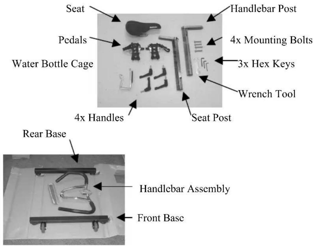
- Open both boxes and verify that you have all of the hardware and parts necessary to assemble your bike. You should have an owner's manual and the following parts:
INSTALLATION INSTRUCTIONS
B. Assemble the Bike
-
With the help of an assistant, lift the bike up and off the pallet.
-
The base that has wheels is the front base and connects to the main frame below the flywheel. Ensure that the wheels are facing out, and align the 2 holes in the front base with the 2 holes in the frame. Insert a mounting bolt into the top of the
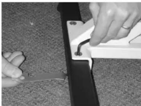
hole and push the bolt through the base and the main frame. Use the 8-mm hex key and wrench tool to secure the mounting bolt nut. Repeat this procedure for the rear base.
Note: If you are having difficulty threading the nut on the bolt, prop up the main frame using the inclosed wooden blocks to allow accessibility to the nut.
INSTALLATION INSTRUCTIONS
- The handlebar post is the post that has a smooth finish, and no groove on top. Insert the handlebar post into the handlebar tube. Loosely thread a handle without a washer into the main frame. Raise the handlebar post to the desired height and tighten the handle to secure the handlebar post.

Note: The black handles are spring loaded. Once tightened, ensure that the handle does not stick out to the side from the main frame. Pull down on the handle and rotate it such that it does not stick out. Release the handle and lock it into place.
-
Position the handlebar over the handlebar post. Loosely thread a handle with a washer through the handlebar post into the handlebar. Slide the handlebar to the desired position and tighten the handle.
-
The 4-mm screw that mounts the water bottle cage is located in the water bottle clamp on the handlebar assembly. Remove the screw from the clamp and position the water
bottle cage over the clamp. Reinstall the screw and tighten the water bottle cage to the clamp.
- The seat post is the post that has a rough finish, and a groove on top. Insert the seat post into the seat post tube. Loosely thread a handle without a washer into the main frame. Raise the seat post to the desired height and tighten the handle to secure the seat post.
INSTALLATION INSTRUCTIONS
- Position the seat with seat slider over the seat post. Loosely thread a handle with a washer through the seat post into the seat slider. Slide the seat to the desired position and tighten the handle.
- The pedals are marked as if you are seated on the bike, "R" for right, and "L" for left. Carefully thread the right pedal into the crank arm with your fingers - do not cross thread the pedal in the crank arm! Use the wrench tool to tighten the pedal. Repeat this step for the left pedal.
Note: The left pedal is reverse-threaded.
- Obtain a complete physical examination from your medical doctor and enlist a health/fitness professional's aid in developing an exercise program suitable for your current health status.
- When working out for the first time, start out slowly for a minimum of five minutes. After your muscles are warmed up, gradually increase the pedaling rate and/or resistance to a speed that allows you to attain your target heart rate zone.
- The speed and duration of your exercise program should always be subject to how you feel. Never permit peer pressure to exceed your personal judgment while exercising.
- Overweight or severely deconditioned individuals should be particularly cautious when using the equipment for the first time. Even though such individuals may not have histories of serious physical problems, they may perceive the exercise to be far less intense than it really is, resulting in the possibility of overexertion or injury.
- Although all equipment manufactured by LeMond ^网 Fitness, Inc. has been thoroughly inspected by the manufacturing facility prior to shipment, proper installation and regular maintenance are required to ensure safety. Maintenance is the sole responsibility of the owner.
BASIC OPERATING INSTRUCTIONS
YOUR FIRST WORKOUT ON THE LEMOND REVMASTER EXERCISE SYSTEM
Basic Instructions for First-Time Users
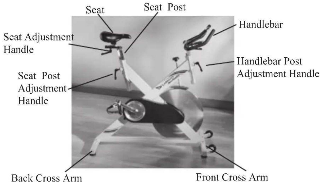
- Properly fit the bike to your body type. The RevMaster offers up/ down and fore/aft adjustments that are clearly marked to ensure a quick and easy custom fit for each workout.
Seat adjustment:
-
Rotate the pedals so that one of the pedals is in the upward position.
-
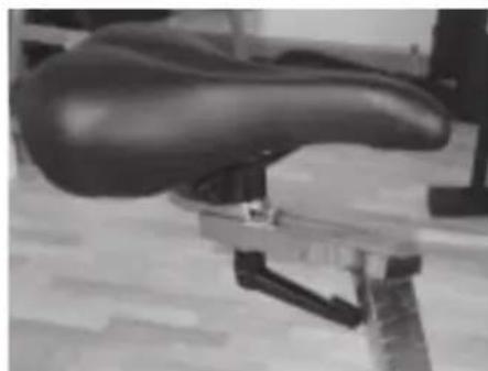
Place your foot in the toe clip of the pedal closest to the floor and mount the bike. Ensure that the ball of your foot is over the center of the pedal. Your leg should be slightly bent at the knee as shown in the picture to the right.
-
If your leg is too straight or your foot cannot touch the pedal you will need to lower the seat.
If your leg is bent too much you will need to raise the seat.
-
Dismount the bike and rotate the seat post adjustment handle counterclockwise. Once loosened you may slide the seat post up or down as necessary.
-
When the seat is in the desired position rotate the seat stem adjustment handle clockwise to secure the seat post. Note the final position mark on the seat stem for future reference.
-
Adjusting the seat fore or aft allows for better fit. Rotate the seat adjustment handle counter clockwise and slide the seat forward or backward as desired. Rotate the seat adjustment handle clockwise to secure the seat. Note the final position mark under the seat for future reference.
Handlebar adjustment:
- Raise or lower the handlebars by rotating the handlebar post adjustment handle counterclockwise and sliding the handlebar post up or down as desired. Rotate the handlebar adjustment handle clockwise to secure the handlebar post. Note the final
BASIC OPERATING INSTRUCTIONS
position mark on the handlebar stem for future reference.
- Adjust the handlebar fore or aft by rotating the handlebar adjustment handle counter clockwise and sliding the handlebar forward or backward as desired. Note the final position mark on the handlebar for future reference.
Pedal strap adjustment:
- Place the ball of each foot on the pedal and in the toe clip such that the ball of the foot is centered over the pedal spindle (center of the pedal).
- Rotate one foot to within arm's reach and pull up on the toe clip strap. Repeat for the other foot.
-
Keep your knees positioned over your foot as you pedal.
-
Once you are in position and sitting comfortably on the bike, slowly begin pedaling. Allow your hands to rest comfortably on the handlebar. If you have not warmed up prior to mounting the bike, pedal slowly for at least five minutes before beginning your exercise program.

WARNING
IF AT ANY TIME DURING YOUR WORKOUT YOU FEEL CHEST PAIN, EXPERIENCE SEVERE MUSCULAR DISCOMFORT, FEEL FAINT, OR ARE SHORT OF BREATH, STOP EXERCISING IMMEDIATELY. IF THE CONDITION PERSISTS, YOU SHOULD CONSULT YOUR MEDICAL DOCTOR IMMEDIATELY.
- Pedaling resistance is controlled by the tension knob located beneath the handlebar on the main "X" part of the frame. Resistance may be changed at any time by turning the tension knob clockwise (more resistance) or counterclockwise (less resistance).
- Before dismounting, push down on the tension knob or rotate the tension knob clockwise to brake the flywheel so that the pedals do not turn freely.
- Dismount the bike by first loosening each toe clip strap and then removing your feet from the pedals. Step off the bike.
GENERAL EXERCISE GUIDELINES
SETTING A GOAL
The first step to a successful exercise program is to set realistic goals and objectives. Are you wanting an exercise program that is geared to build muscle, maintain muscle tone, or lose weight? In order to ensure that you fully receive all the benefits of a sound exercise program, you need to first identify the existence (if any) of risk factors that may influence the design of your exercise program. Based upon a comprehensive analysis of your personal exercise needs and interests, you should then develop (or have developed for you by a competent or trained professional) an individualized program of exercise that is enjoyable, easy, and yet challenging. Your greatest health benefit will come from a lifestyle change that encourages a lifetime of physical activity.
One way to guarantee success in reaching your goal is to eat correctly. A well-rounded diet provides the proteins, carbohydrates, fats, vitamins, minerals, and water necessary for good health. If you are unsure of your dietary needs, seek the advise of your physician, an exercise professional, or visit your local bookstore for more information on nutrition.
FLEXIBILITY TRAINING*
Achieving and maintaining an adequate range of motion should always be objectives of a comprehensive exercise program. The warm-up phase of your exercise session should include some type of light warm-up activity to increase both your heart rate and your body temperature, which is then followed by flexibility exercises that are specifically designed to stretch the musculature around your body's major skeletal joints. Attempting to stretch a cold muscle can be dangerous to the soft tissues surrounding the muscle. No matter how controlled the movement, forcing a muscle through a full range of motion (and beyond) without appropriately warming up is both unsafe and counterproductive.
A general exercise program for achieving and maintaining flexibility should adhere to the following guidelines:
Frequency - daily
- Intensity - to a position of mild discomfort
GENERAL EXERCISE GUIDELINES
- Duration - 10-30 seconds for each stretch
Repetitions - 2-6 for each stretch - Type - static, with a major emphasis on the low back and hamstrings area because of the high prevalence of low-back pain syndrome in our society.
EXERCISE PRINCIPLES*
The American College of Sports Medicine has developed a position paper concerning exercise programs for healthy adults and the need for guidelines. The following recommendations concern the quantity and quality of (exercise) training for developing and maintaining cardiorespiratory fitness in a healthy adult:
Frequency -3 to 5 days per week
- Intensity -50% - 85% of maximum oxygen uptake (VO_2)
Duration -20 to 60 minutes of continuous aerobic activity
Mode of Activity -Any activity that uses the large muscle groups, that can be maintained continuously, and is rhythmical and aerobic in nature.
- Rate of Progression -Initial Conditioning - 4 to 6 weeks; low-end intensity (40% - 60% VO _2 ); low-end duration (15 to 20 minutes). -Improvement Stage - 6 weeks to 6 months; moderate intensity; moderate duration.
-Maintenance Stage - 6 months plus; moderate to high intensity; moderate to high duration.
MAINTENANCE INSTRUCTIONS
HELPFUL HINTS
The safety level given by the design of this equipment can only be maintained when the equipment is regularly examined for damage and wear. Inoperable components should be replaced immediately or the equipment should be put out of use until it is repaired. Read all maintenance instructions thoroughly before beginning work.
All references to the right or left side and to the front or back are made as if you were on the exercise equipment ready to exercise. For example, the belt is on the right side of the bike.
TOOL LIST
The following tools are needed to perform service and maintenance:
• C o m b i n a t i o n w r e n c h
• M e t r i c a l l e n w r e n c h e
• P h i l l i p s ™ s c r e w d r i v e r
S h f-compatible bottom bracket tool +1 / 2'' driver
• L o c k r i n g r e m o v a l t c
• B i c y c l e ™ c r a n k ™ a r m ™ p u
INITIAL SERVICE
Upon receiving your equipment, use a soft clean cloth to wipe off the dust that may have accumulated during shipping. Your equipment will need minor assembly. Refer to the "Installation Instructions" section of this manual for details.
PREVENTIVE MAINTENANCE
Refer to the appropriate "Parts Removal and Replacement" section of this manual for all disassembly and assembly instructions. If you experience any problems, contact our Customer Service Department at (425) 482-6773.
MAINTENANCE INSTRUCTIONS
Daily
- Wipe down the LeMond ^® RevMaster after each use to remove sweat and moisture. Use soap and water, or a diluted non-abrasive cleaner solution. Rinse to remove detergent residue and then dry.
- If your bikes are used frequently in group exercise sessions, inspect for loose pedals prior to starting any class. Tighten any loose pedals.
Weekly
- Inspect the brake pad for excessive wear or dryness. If necessary, lubricate the leather brake pad with 3-N-ONE® oil. If the sponge padding is showing through the brake pad, replace the brake pad.
- Wipe down the flywheel with WD-40. This product will clean the surface of the flywheel and provide a protective barrier against moisture.
Monthly
- Inspect the belt for correct alignment and tension. A properly tensioned belt will not slip when pedaling the bike standing up. Check the belt for excessive wear. Replace any belt that is cracked, frayed, or otherwise non-uniform.
- Inspect the bottom bracket assembly for looseness. The left bearing cup is adjustable, and over time may loosen. With a small rubber mallet, tap on the crank bolt on both sides If you see side to side movement you must remove the crank arm(s) and properly adjust the bearing cup(s).
TROUBLESHOOTING
This section outlines tests to systematically identify and isolate the cause of common problems. The first step is to identify the problem. Once you have identified the problem, perform the tests in exactly the same order as written. Refer to the appropriate "Parts Removal and Replacement" section of this manual for all disassembly and assembly instructions. To order a replacement part, or to get help with the troubleshooting process, contact the Customer Service Department at (425) 482-6773.
SYMPTOM: Adjustment handles do not engage
- If the adjustment handle fails to engage properly replace the adjustment handle.
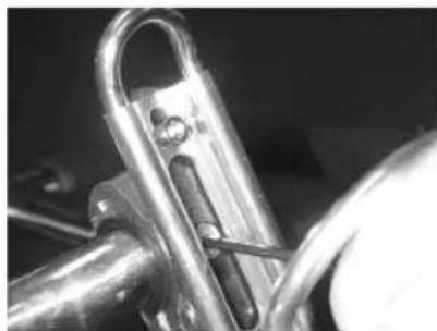
SYMPTOM: Handlebar/Seat post will not slide in the frame tube
- Remove handlebar/seat post and look down inside of the frame tube. TheV-Plunger may have fallen out of its proper location and could be blocking the tube. If necessary, push the V-Plunger back into position with your fingers. Reinstall the handlebar/seat post and adjustment handle.
SYMPTOM: Pedals are slipping
- Inspect the belt for proper tension. If necessary, tighten the belt.
SYMPTOM: Knocking noise or play felt in pedals/crank
- Inspect the pedal crank arm bolts. If they have loosened, apply Loctite® on the crank arm bolt threads and tighten.
- If the symptom is still there, check the bottom bracket bearing cups for looseness. Tighten if necessary.
- If the symptom still persists, remove the bottom bracket bearings. Replace the bottom bracket assembly if necessary.
SYMPTOM: Crank arms do not rotate
- Remove the pedals crank arms and try to rotate the bottom bracket shaft. Ensure that the bottom bracket bearing cups have not loosened and backed into the crank arms. Adjust the bearing cups and use Loctite to secure the bottom bracket bearing cups.
- If the bottom bracket bearing cups are too tight, loosen the bearing cups and try to rotate the bottom bracket shaft. If it does not rotate, replace the bottom bracket bearings.
PARTS REMOVAL AND REPLACEMENT
ADJUSTMENT HANDLES
Handlebar/Seat post adjustment handle
- Support the post with one hand and rotate the adjustment handle counterclockwise with your other hand until the handle is unthreaded from the frame.
- Lower the post so that it rests on the frame.
- Apply a thin layer of grease on the threads from half way to the end of the threads. Thread the new handle halfway into the frame. Position the post in the desired location. Rotate the adjustment handle clockwise to secure the post.
- Ensure that the handle does not stick out to the right or left. Each handle is spring loaded so that you can properly align the frame and the handle. Simply pull out on the handle and rotate it for correct alignment.
Handlebar/Seat adjustment handle
- Rotate the adjustment handle counterclockwise to loosen the seat and/or handlebar.
- Slide the seat back or the handlebar forward on the frame.
- Continue rotating the handle counterclockwise until it is un-threaded from the seat and/or handlebar.
- Apply a thin layer of grease on the threads from half way to the end of the threads. Thread the new handle halfway into the seat and/or handlebar. Position the seat and/or handlebar in the desired location. Rotate the adjustment handle clockwise to secure the seat and/or handlebar.
Note: The seat slider has two holes from which to position the seat.
- Ensure that the handle does not stick out to the right or left. Each handle is spring loaded so that you can properly align the frame and the handle.
Simply pull out on the handle and rotate it for correct alignment.
PARTS REMOVAL AND REPLACEMENT
BELT
- Remove the front cover.
- Loosen the shoulder bolt with an adjustable wrench.
- Use the allen wrench to loosen the belt tensioner screw located on top of the idler tension bearings.
- You will need a rubber coated wrench (or similar tool) for this
next step. Position the rubber coated end of the tool between the frame and the belt. Slowly rotate the pedals forward and pull the belt off the front and back pulleys.
- Install the new belt by reversing steps 1-4.
BOTTOM BRACKET BEARINGS
I. Remove each Crank Arm.
2. Use an 8-mm hex key to remove the pedal crank bolt.
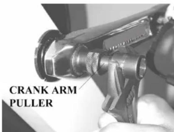
3. Thread a bicycle crank arm puller onto the crank arm shaft.
4. As you tighten the crank arm puller on the shaft, the crank
arm will pull off the crank arm shaft. Remove the crank arm from the frame.
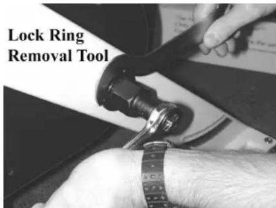
-
Loosen the lock ring on the left side of the bike using a lock ring removal tool.
-
Ensure that the right bearing cup is tight. If necessary, tighten with the bottom bracket tool. Note: the right bearing cup is reverse threaded!
-
Check the left bearing cup. If the bearing cup is loose, tighten with your fingers. Use the bottom bracket tool to tighten
PARTS REMOVAL AND REPLACEMENT
the bearing cup - rotate the bottom bracket tool an additional 10 degrees clockwise.
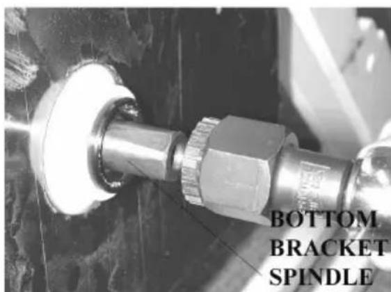
- Verify that the bottom bracket spindle is not loose by tugging on the spindle shaft.
- Use the lock ring removal tool to tighten the lock ring.
Note: Prevent the left bearing cup from spinning by stabilizing it with the bottom bracket removal tool.
- Apply a thin coat of grease on the left bottom bracket shaft and install the left crank arm on the bottom bracket shaft. Note: use a rubber mallet to tap the arm onto the bottom bracket spindle.
- Apply 1-2 drops of Locktite ^242 on the left crank arm bolt threads. Install the crank arm bolt and tighten to secure the crank arm. Rotate the pedals a few revolutions and then tighten the crank arm bolt again to ensure that the crank arm is tightened to 22 foot/lbs.
- Apply a thin coat of grease on the right bottom bracket shaft and install the right crank arm on the bottom bracket spindle. Align the right crank arm 180^ from the left crank arm and push the crank arm on to the crank arm shaft.
- Apply 1-2 drops of Locktite 242 on the right crank arm bolt threads. Install the crank arm bolt and tighten to secure the crank arm. Rotate the pedals a few revolutions and then tighten the crank arm bolt again to ensure that the crank arm is tightened to 22 foot/lbs.
- Reinstall the belt. Test the belt tension by standing on the pedals with the pedals horizontal to the floor. Pedal quickly and see if the belt slips. A minimum of slipping is okay, it is important not to overtighten the belt.
- Reinstall the right side cover.
Note: Inspect the pedal crank arm bolts again after 30 hours (approx. one week). If loose, remove the bolts; apply Loctite 242 and reinstall. Tighten the bolts to 22 foot/lbs.
PARTS REMOVAL AND REPLACEMENT
BRAKE PAD ASSEMBLY
-
Turn the tension knob counterclockwise to remove tension on the brake pad assembly.
-
Remove the brake pad mounting nut and screw from the brake pad spring using a 10-mm wrench and 4-mm allen wrench. Note the location of the two different 4-mm mounting screws that hold the brake pad in place.
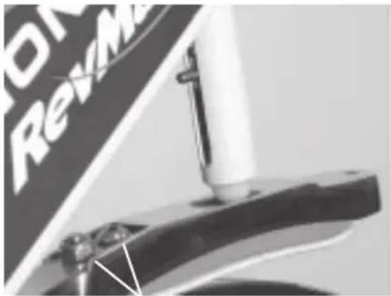
Brake Pad Mounting Nut and Screw
- Remove the brake pad assembly from the frame and place the brake pad assembly on a flat surface.
- Remove both mounting screws from the brake pad using the 4-mm allen wrench.
- Pull the old brake pad off the brake pad housing. Next, clean the adhesive backing material out from the brake pad housing. Use a pocketknife to clean out any large pieces of debris.
- Peel the non-stick backing off the foam on the new leather brake pad and install the new leather brake pad, orienting it so that the adhesive backing aligns with the underside of the brake pad housing. Insert the 4-mm socket cap screw through the correct mounting hole in the new leather brake pad (the correct mounting hole in the brake pad material is closer to the edge in front, and further from the edge in back).
- Use the 4-mm allen wrench to align the screw into the mounting hole on the brake pad housing and partially thread the screw into the brake pad housing.
- Insert the other mounting screw through the leather pad and into the brake pad housing. Tighten both screws. The back screw is longer and will go through the brake pad housing so that the brake spring steel can attach to it.
- Install the new brake pad assembly by reversing steps 1-8.
PARTS REMOVAL AND REPLACEMENT
COVERS
Front Cover
- Using the screwdriver remove the four screws that secure the cover to the frame and back cover.
- Slide the cover over the right pedal crank and remove the cover from the frame.
Back Cover
- Using the screwdriver remove the five screws that secure the cover to the frame and the front cover.
- Remove the front cover.
- Remove the remaining screws that secure the back to the frame. Slide the back cover over the right pedal crank and remove the cover from the frame.
FLYWHEEL/PILOW BLOCK BEARINGS
Note: The flywheel weighs 47 pounds; it is recommended to have an assistant help you with the replacement of the flywheel.
- Remove the belt.
- Using a 5mm allen wrench remove the two mounting bolts that secure each of the pillow block bearings on either side of the flywheel to the frame.
- Have an assistant help you lift the flywheel up and remove the flywheel from the frame.
- Place the flywheel on a padded surface with the pulley side facing up.
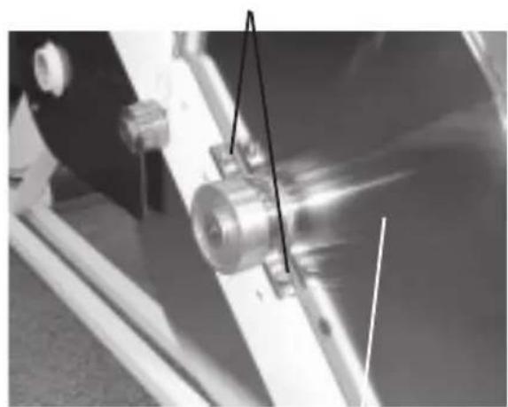
Pillowblock Bearing
Flywheel
Note: Lay the flywheel down on a padded surface. Any surface damage (nicks, dings, etc.) to the flywheel will effect performance
PARTS REMOVAL AND REPLACEMENT
- Use a 4mm allen wrench to remove the pulley from the flywheel.
- Pull the right pillow block bearing off the flywheel shaft.
- Flip the flywheel over on the floor.
- Pull the left pillow block bearing off the flywheel shaft.
- Use a 4mm allen wrench to remove the three flat head allen screws from the flywheel.
- Remove the spline shaft from the flywheel.
- Install the new flywheel by reversing steps 1-10. Use Loctite on the three flat head screws when reinstalling the flywheel shaft.
HANDLEBAR
- Rotate the handlebar adjustment handle counterclockwise and unscrew the handle from the handlebar.
- Lift the handlebar off the handlebar post and remove it from the frame.
- Align the adjustment groove in the new handlebar with the adjustment groove in the handlebar post.
- Apply a thin layer of grease on the threads from half way to the end of the threads. Insert the handlebar adjustment handle into the groove with the handle located below the handlebar. Do not tighten.
- Position the handlebar in the desired location and rotate the handlebar adjustment handle clockwise to secure the handlebar.
- Ensure that the adjustment handle does not stick out to the right or left. Each handle is spring loaded so that you can properly align the frame and the handle. Simply pull out on the handle and rotate it for correct alignment.
HANDLEBAR POST
- Remove the handlebar from the handlebar post.
- Support the handlebar post with one hand.
- Use your other hand to rotate the handlebar post adjustment handle counterclockwise.
- Unscrew the handlebar post adjustment handle halfway out from the frame.
- Lift the handlebar post out of the frame.
- Insert the new handlebar post into the frame. Position the handlebar
PARTS REMOVAL AND REPLACEMENT
post in the desired location and rotate the handlebar post adjustment handle clockwise to secure the handlebar post.
Note: If the post will not slide all the way down you will need to push the V -plunger back inside the frame tube.
- Reinstall the handlebar.
PEDALS
- Block the crank arm from spinning, and use a bicycle wrench on the pedal nut to remove the pedal from the crank arm.
- LEFT PEDAL: Turn the pedal nut clockwise and remove the pedal from the pedal crank.
- RIGHT PEDAL: Turn the pedal nut counterclockwise and remove the pedal from the pedal crank.
- Install the new pedal(s) by lightly greasing the pedal nut threads and reversing steps 1-3.
PEDAL CRANK ARMS
Left Crank Arm
- Using an 8-mm wrench, remove the crank arm bolt.
- Thread a bicycle crank arm removal tool onto the crank arm shaft .
- As you tighten the crank arm removal tool on the shaft, the crank arm will pull off the crank arm shaft. Remove the crank arm from the frame.
- Apply a thin coat of grease on the bottom bracket spindle and align the new crank arm 180^ from the right crank arm and push the crank arm onto the crank arm shaft.
- Apply a thin coat of grease on the crank arm bolt. Install the crank arm bolt and tighten to secure the crank arm. Rotate the pedals a few revolutions and then tighten the crank arm bolt again to ensure that the crank arm is tight.
PARTS REMOVAL AND REPLACEMENT
Right Crank Arm
- Remove the front cover and belt.
- Using an 8-mm wrench, remove the crank arm bolt.
- Thread a bicycle crank arm removal tool onto the crank arm shaft .
- As you tighten the crank arm removal tool on the shaft, the crank arm will pull off the crank arm shaft. Remove the crank arm from the frame.
- Apply a thin coat of grease on the bottom bracket spindle and align the new crank arm 180^ from the left crank arm and push the crank arm on to the crank arm shaft.
- Apply a thin coat of grease on the crank arm bolt. Install the crank arm bolt and tighten to secure the crank arm. Rotate the pedals a few revolutions and then tighten the crank arm bolt again to ensure that the crank arm is tight.
- Reinstall the belt and front cover.
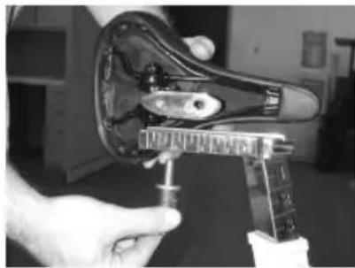
SEAT
- Use an adjustable wrench to loosen each nut on either side of the seat.
- Lift the seat off the seat slider.
- Position the new seat on the seat slider, level the seat, and evenly tighten each seat nut.
Note: Ensure that the nuts on the seat clamp are fully tightened to prevent the seat from moving during use.
SEAT SLIDER
- Rotate the seat adjustment handle counterclockwise and unscrew the handle from the seat.
- Lift the seat slider off the seat post and remove it from the frame.
- Align the adjustment groove in the new seat slider with the adjustment groove in the seat post.
- Insert the seat adjustment handle into one of two position holes in the seat slider. Do not tighten.
- Position the seat in the desired location and rotate the seat adjustment
FIGURES
handle clockwise to secure the seat.
- Ensure that the handle does not stick out to the right or left. Each handle is spring loaded so that you can properly align the frame and the handle. Simply pull out on the handle and rotate it for correct alignment.
SEAT POST
- Remove the seat from the seat post.
- Support the seat post with one hand.
- Use your other hand to rotate the seat post adjustment handle counterclockwise.
- Unscrew the seat post adjustment handle halfway out from the frame.
- Lift the seat post out of the frame.
- Insert the new seat post into the frame. Position the seat post in the desired location and rotate the seat post adjustment handle clockwise to secure the seat post.
- Ensure that the handle does not stick out to the right or left. Each handle is spring loaded so that you can properly align the frame and the handle. Simply pull out on the handle and rotate it for correct alignment.
- Reinstall the seat.
TENSION KNOB ASSEMBLY
- Turn the tension knob counterclockwise to remove tension.
- Remove the 2 mounting screws from the black plastic cover, below the knob.
- Unscrew the plastic acorn nut from the bottom of the tension knob assembly.
- Pull the bottom spring off the brake tension rod and out from the main frame.
- Lift the tension knob assembly out from the frame.
- Install the new tension knob assembly by reversing steps 1-5.
FIGURES
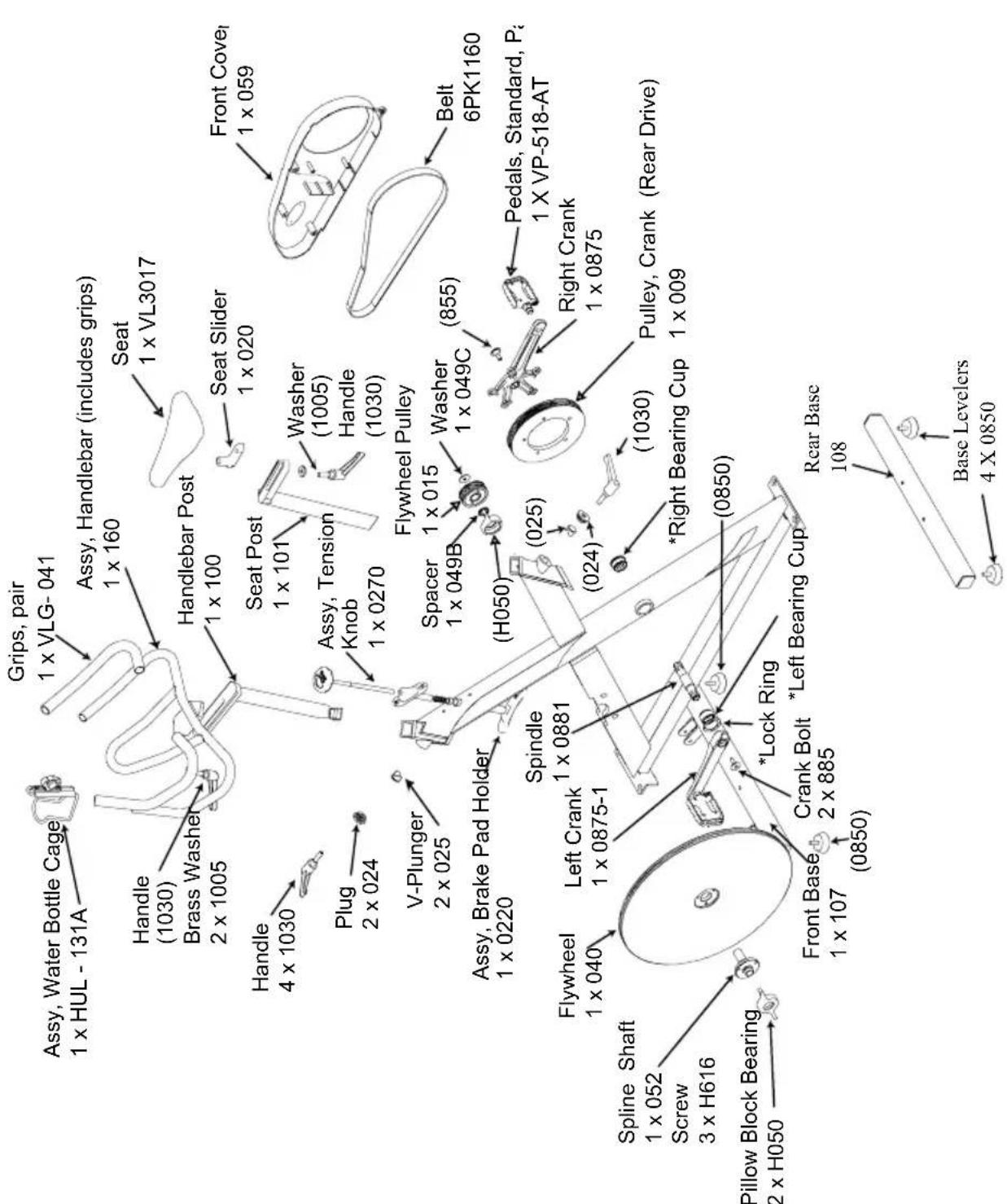
Figure 1: Final Assembly
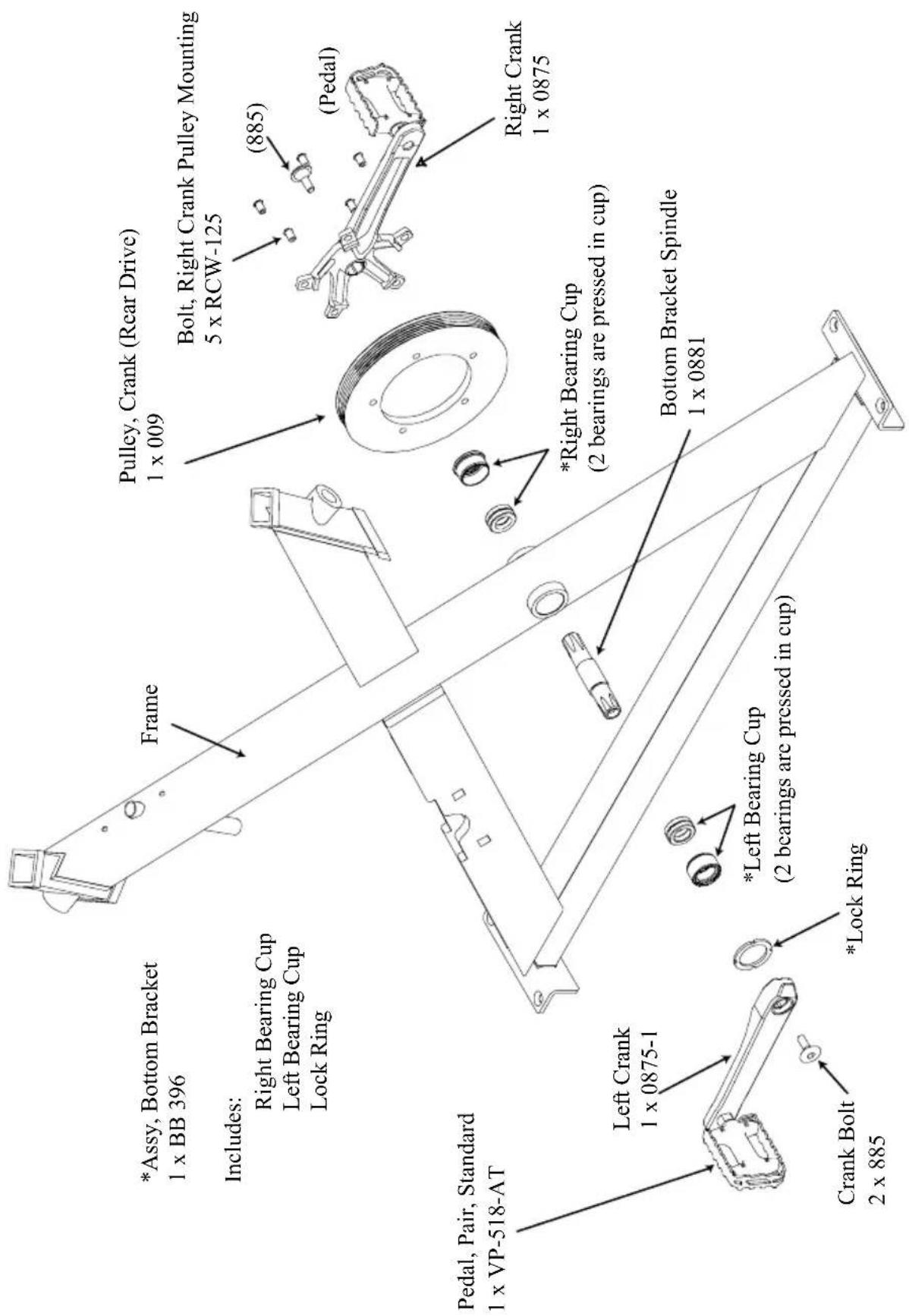
Figure 2: Crank Assembly
FIGURES
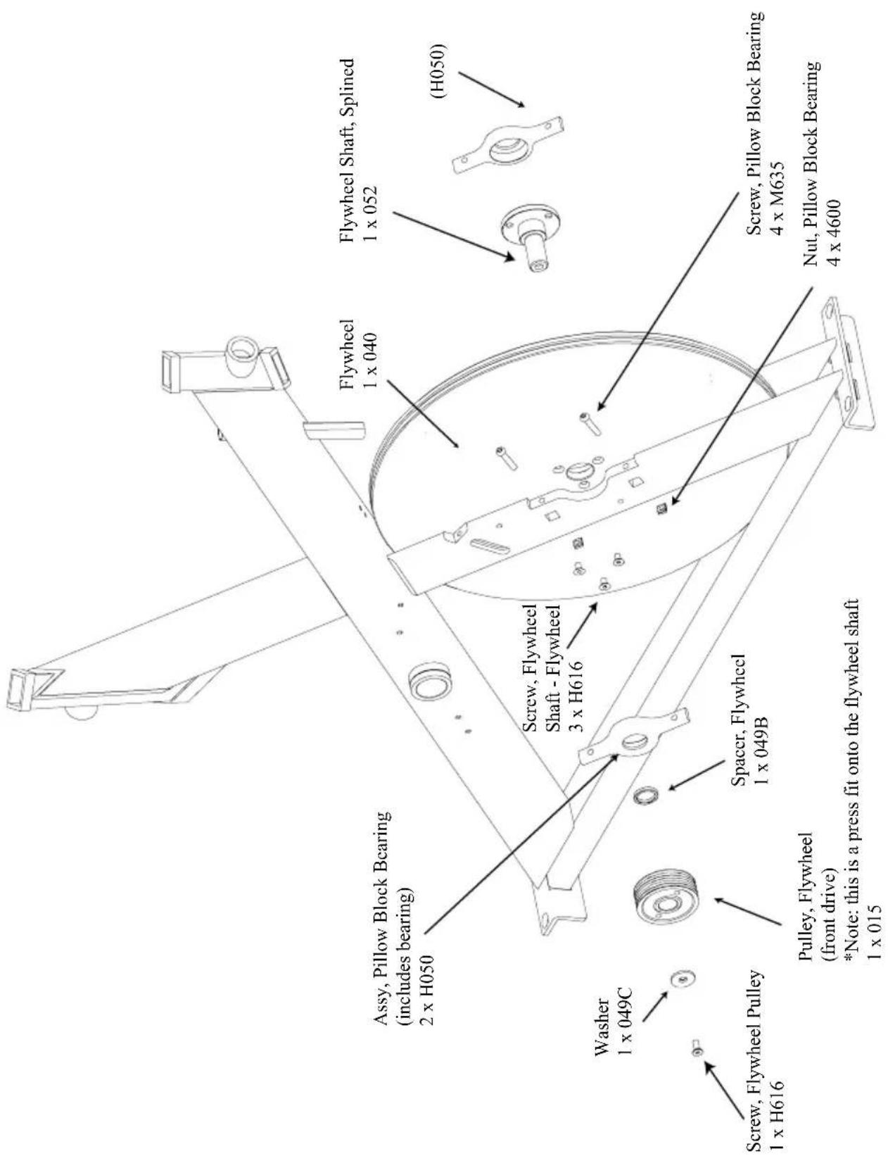
Figure 3: Flywheel Assembly
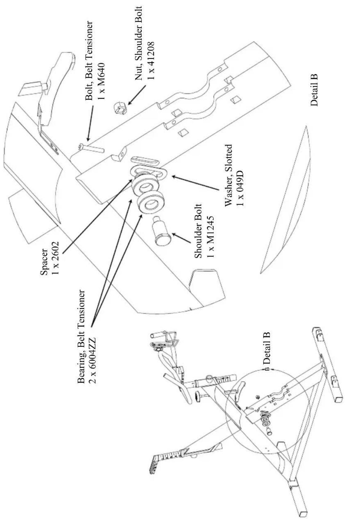
Figure 4: Belt Tension
FIGURES
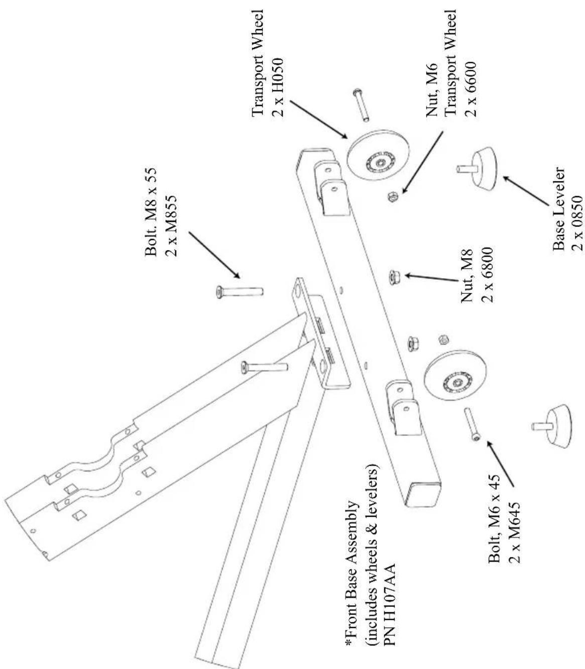
Figure 5: Front Base Assembly
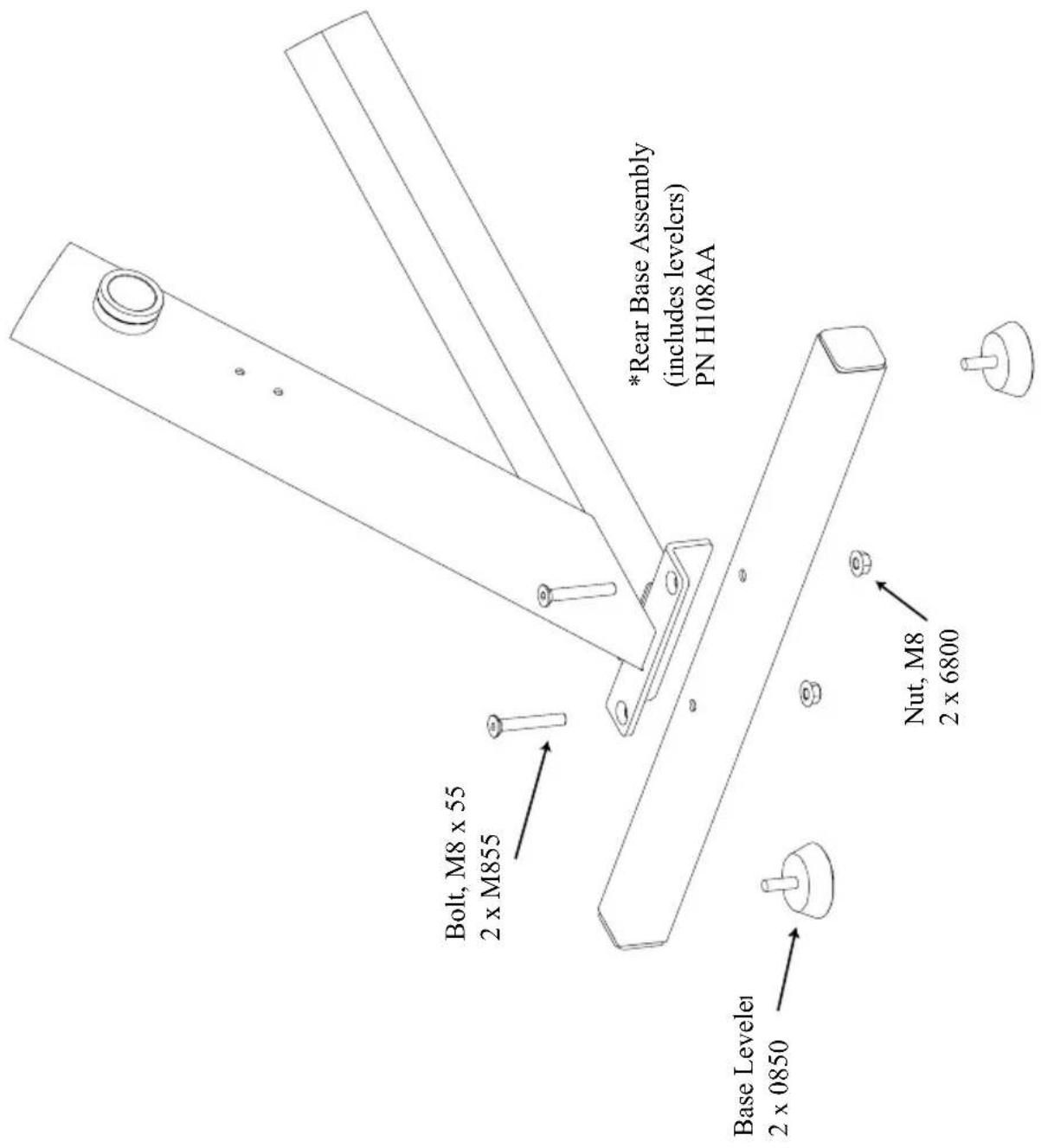
Figure 6: Rear Base Assembly
FIGURES
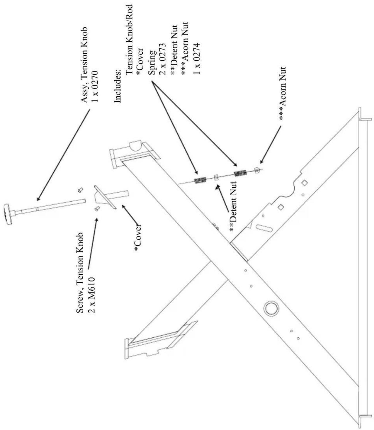
Figure 7: Brake Tension Knob Assembly
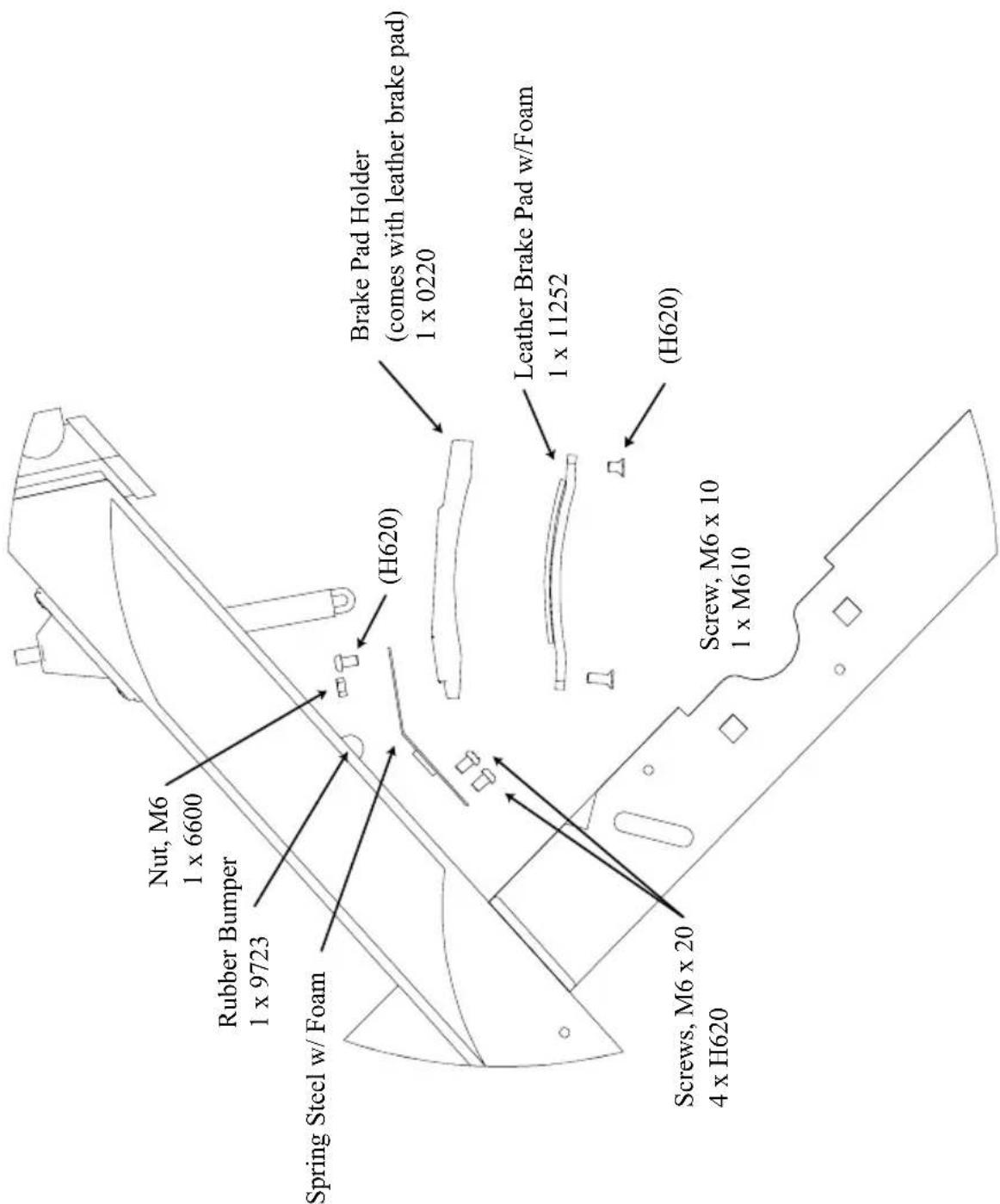
Figure 8: Brake Pad Assembly
FIGURES
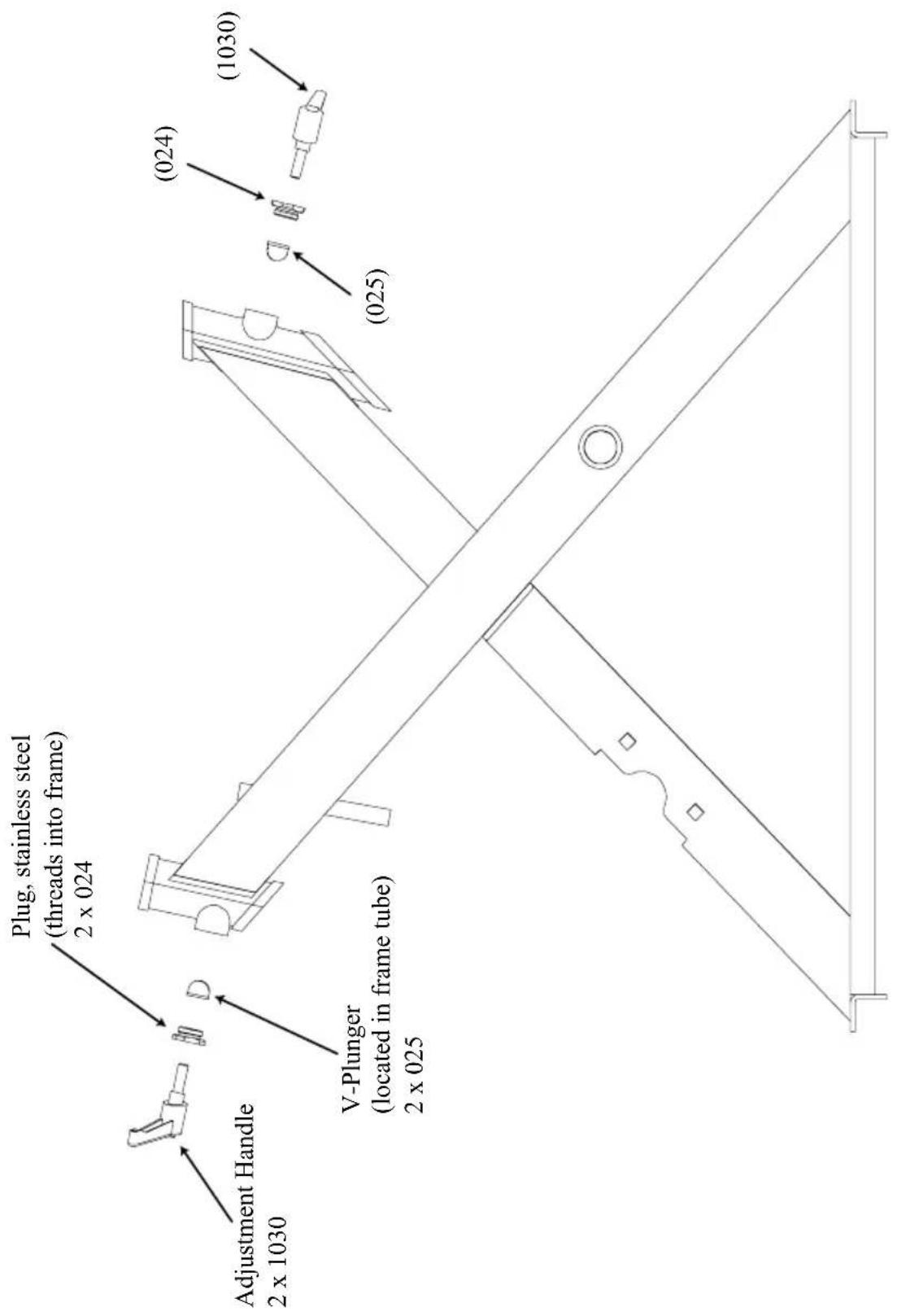
Figure 9: V-Plunger & Plug
SPECIFICATIONS
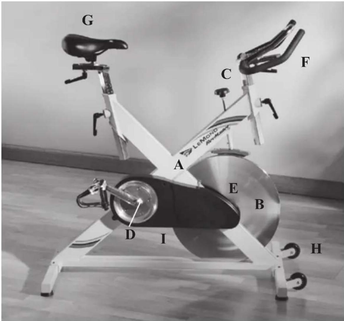
A - Frame:
-Ultra-strong, X-Style Design
Welded frame and bolted base
- Stainless steel components
-22 inch wide base with extra large diameter adjustable levelers
B - Flywheel:
-47-pound precision-machined, chrome-plated flywheel
- Machined stainless steel axle
C - Braking and resistance mechanism:
- Turn-knob design for tension; push down for braking
- Leather resistance pad on top of flywheel for improved durability
D - Crank set:
- Cast stainless steel & chrome plated cranks (170 mm)
- Exceptionally strong, Cr-Moly machined BMX bottom bracket spindle (23.0 mm x 124.5 mm)
- Bearing cups fit standard road bike frame & have 2 bearings per cup - 4 total
E - Flywheel Adjustment:
- Flywheel requires no adjustment
F-Handlebars:
Biomechanically correct w/anatomical bend
Stainless steel, adjust up/down and fore/aft
Rubber grip
- Unique V-clamp and rotated tube design for enhanced stability
- Adjustment marks for up/down, fore/aft
Stainless steel post and tube
SPECIFICATIONS
G - Seat:
- Stainless steel dual position seat slider adjusts fore/aft
- Unique V-clamp and rotated tube design for enhanced stability
- Adjustment marks for up/down and fore/aft
Stainless steel post adjusts up/down
H - Transport Wheels:
-Extra large in-line skate wheels
- Wheel brackets are welded to the frame
I - Drive Train:
Non-slip, durable belt
- Accessible without removing the flywheel
- Kevlar reinforced
MANUEL DE L'UTILISATEUR
LeMond Fitness Inc.
17820 Woodinville-Redmond Rd.
Building B, Suite 888
Telephone:(425)482-6773
Télécopie: (425) 482-6724
www.LeMondfitness.com
Ref. 300202
Figure 1: Ensemble final 24
Figure 2: Manivelle 25
Figure 3: Volant 26
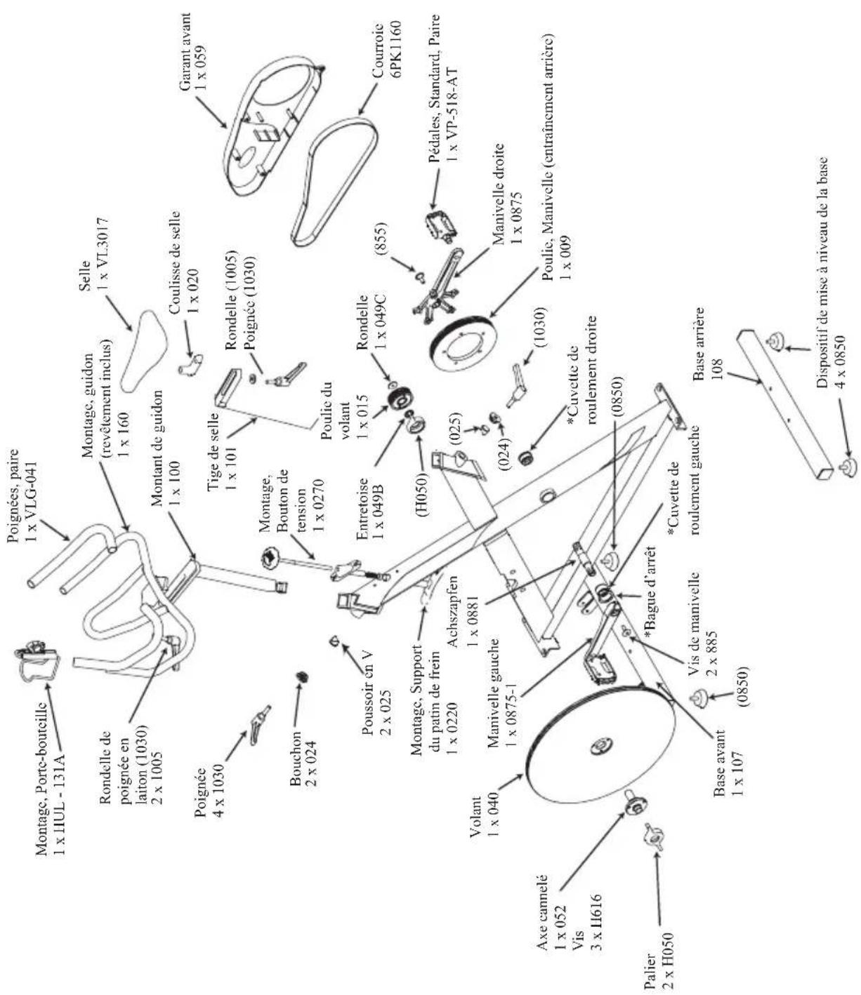
Figure 1: Ensemble final
FIGURES
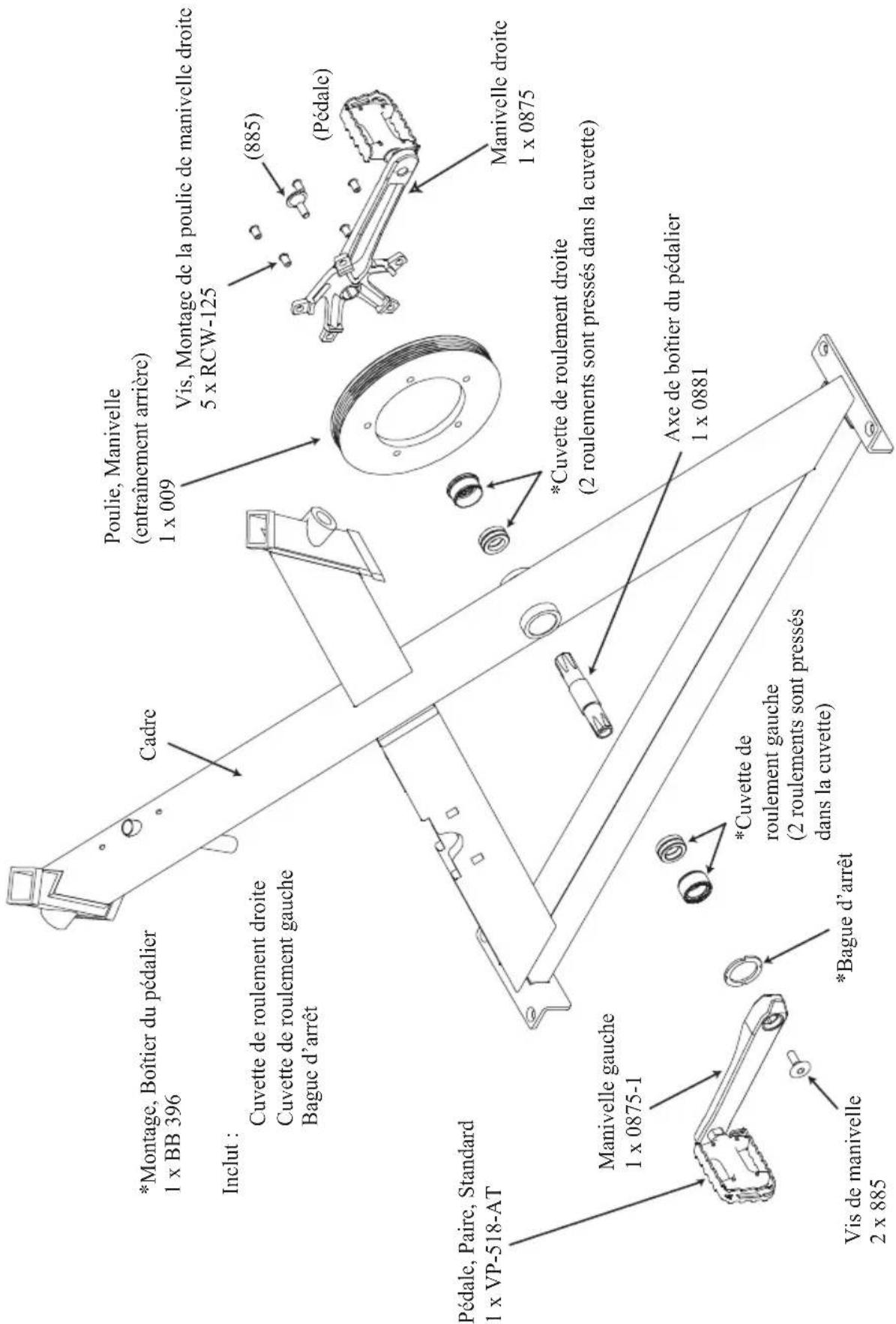
Figure 2: Manivelle
FIGURES
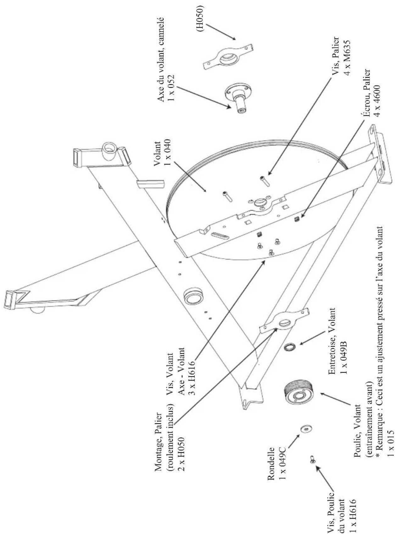
Figure 3: Volant
17820 Woodinville-Redmond Rd.
Building B, Suite 888
Tel.: (425) 482-6773
Telefax: (425) 482-6724
www.LeMondfitness.com
Teile-Nr. 300202
17820 Woodinville-Redmond Rd.
Building B, Suite 888
Tel.: (425) 482-6773
Fax: (425) 482-6724
Visite{nuestra website
www.LeMondfitness.com