Theseus SF1620 - Exercise bike Skandika - Free user manual and instructions
Find the device manual for free Theseus SF1620 Skandika in PDF.

| Product type | Exercise bike |
| Brand | Skandika |
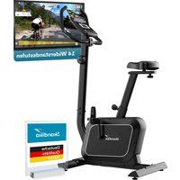
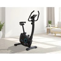
| Model | Theseus SF1620 (Special Edition Joey Kelly) |
| Braking system | Magnetic |
| Maximum user weight | 120 kg |
| Power supply | 2 AA 1.5 V batteries (alkaline recommended) |
| Computer display | Speed, time, distance, calories, pulse, RPM, date, time, ambient temperature |
| Computer functions | Scan, target value setting, Recovery mode (recovery index F1 to F6), reset |
| Pulse sensors | Manual (hand grips) |
| Resistance adjustment | Manual via knob on handlebar stem |
| Seat adjustment | Height and horizontal position |
| Handlebar adjustment | Height, with adjustable grip angle |
| Pedals | Right (R) and left (L), screwed in direction of rotation |
| Transport wheels | Yes (on front foot) |
| Adjustable feet | Yes (on rear foot) |
| Intended use | Household use only |
| Break-in period | The new V-belt may feel heavy at first – normal |
| Maintenance | Regularly check screws and connections; clean with a damp cloth; replace batteries if display is weak |
| Spare parts | Available via SKANDIKA (see exploded view and parts list in the manual) |
| Warranty | 24 months (excluding wear parts and non-compliant use) |
Frequently Asked Questions - Theseus SF1620 Skandika
User questions about Theseus SF1620 Skandika
0 question about this device. Answer the ones you know or ask your own.
Ask a new question about this device
Download the instructions for your Exercise bike in PDF format for free! Find your manual Theseus SF1620 - Skandika and take your electronic device back in hand. On this page are published all the documents necessary for the use of your device. Theseus SF1620 by Skandika.
USER MANUAL Theseus SF1620 Skandika
Congratulations on your purchase of the CardioBike Theseus!
This hometrainer with magnetic brake system is designed for a home- training to improve your endurance and your heart-/blood-circular system. Also, this bike may be used in combination with a dietary program for weight loss and body fat reduction. Please consult your physician and a professional nutrition advisor. To ensure a correct and most effective way of exercise, it is absolutely necessary to read and observe all the points in this manual.
This tread crank-training-item is suitable for home-use with a maximum user weight of 120kg and is not suitable for therapeutically use. Don't set up this item in public places. This item may only be used in the way described in this manual. This item is RPM-dependent - you can adjust the load / intensity with the help of the computer.
During the very first exercise minutes, the pedal movement may occur very difficult. This may be caused by the brandnew driving band and is a normal condition.

IMPORTANT INFORMATION! RETAIN FOR FUTURE USE!
Read the instruction manual carefully before using this device - especially the safety instructions - and keep the instruction manual for future use. Should you give this device to another person, it is vital that you also pass on these instructions for use.
Contents
Safety instructions 30
Assembly
Parts list 31
Set-up 34
User manual
Computer | Use 41
Heart recovery rate measurement 44
Battery replacement. 45
In the interest of environmental protection. 46
Exercise hints 46
Pulse chart 49
Set-up- and Explosion drawing 50
Care/Warranty terms. 52
Visit our Website for more information www.skandika.com
Scan the QR-Code with your smartphone

SAFETY INSTRUCTIONS
Safety Instructions
- The maximum load of this device is 120kg .
- To ensure the best safety of the exerciser, regularly check it on damages and worn parts.
If you pass on this exerciser to another person or if you allow another person to use it, make sure that that person is familiar with the content and instructions in these instructions. - Only one person should use the exerciser at a time.
- Before the first use and regularly make sure that all screws, bolts and other connections are properly tightened and firmly seated.
- Before you start your work-out, remove all sharp-edged objects around the exerciser. Only use the exercise for your workout if it works flawlessly. Pay attention, that no heat sources are present in the range of the device or the mains cable.
- Any broken, worn or defective part must immediately be replaced and/or the exerciser must no longer be used until it has been properly maintained and repaired.
- This device is not designed to be used by persons (including children) with limited physical, sensory or mental abilities, or by persons with insufficient experience and/or knowledge, unless under observation by a person responsible for their safety, or unless they have been instructed in the use of the device.
Children must be supervised to ensure that they do not play with the device. - Make sure there is sufficient free space around the exerciser when you set it up.
If you should have concerns about your health, consult a doctor before using. - The device must only be used for its intended purpose as described in the instruction manual. Using the unit for any other purpose invalidates the warranty.
- Please note that an improper and excessive work-out may be harmful to your health.
- Please note that levers and other adjustment mechanisms are not projecting into the area of movement during the workout.
- When setting up the exerciser, please make sure that the exerciser is standing in a stable way and that any possible unevenness of the floor is evened out.
- Always wear appropriate clothing and shoes which are suitable for your work-out on the exerciser. The clothes must be designed in a way so that they will not get caught in any part of the exerciser during the work-out due to their form (for example, length). Be sure to wear appropriate shoes which are suitable for the work-out, firmly support the feet and which are provided with a non-slip sole.
- Be sure to consult a physician before you start any exercise program. He may give you proper hints and advice with respect to the individual intensity of stress for you as well as to your work-out and sensible eating habits.
- Do not use this device in the vicinity of aerosol products or gases, which are inflammable by flying sparks.
SAFETY INSTRUCTIONS / PARTS LIST
- Assemble the exerciser as per assembly instructions and be sure to only use the structural parts provided with the exerciser and designed for it. Prior to the assembly, make sure the content of the delivery is complete by referring to the parts list of the assembly and operating instructions.
- Be sure to set up the exerciser in a dry and even place and always protect it from humidity. If you wish to protect the place particularly against pressure points, contamination, etc., it is recommended to put a suitable, non-slip mat under the exerciser. Do not place the device on a carpet!
- The general rule is that exercisers and training devices are no toys. Therefore, properly informed or instructed persons must only use them.
- Stop your work-out immediately in case of dizziness, nausea, chest pain or any other physical symptoms. In case of doubt, consult your physician immediately.
- Children, disabled and handicapped persons should use the exercise only under supervision and in presence of another person who may give support and useful instructions.
- Be sure that your body parts and those of other persons are never close to any moving parts of the exerciser during its use.
- When adjusting the adjustable parts, make sure they are adjusted properly and note the marked, maximum adjusting position, for example of the saddle support, respectively.
- Do not work out immediately after meals!
| Part no. | Description Specifications Q'ty | ||
| A Computer assembly 1 Set | |||
| A-1 Computer (ABS) 1 | |||
| A-2 Screw M5x10mm 4 | |||
| B Handlebars assembly | 1 Set | ||
| B-1 | Foam grip | (PVC) | 2 |
| B-2 | Self-tapping screw | ST4.0x20 | 2 |
| B-3 | Handpulse | 2 | |
| B-4 | Handlebars | 1 | |
| B-5 | Cap | (PP)ø27mm | 2 |
| B-6 | Handpulse cable | 550+550mm 2 | |
| C | Handlebars post assembly | 1 Set | |
| C-1 | Handlebars post | 1 | |
| C-2 | End cap | 15mm | 1 |
| C-3 | Computercable, upper part | 1050mm | 1 |
| C-4 Curved washerø 8 xø | 19 x 2t | 4 | |
| C-5 | Screw | M8x16mm 4 | |
| C-6 | Tension controller with cable | (ABS) 800mm | 1 |
| C-7 Curved washer5mm | 1 | ||
| C-8 | Screw | M5x35mm 1 | |
| D | Main frame assembly | 1 Set | |
| D-1 | Main frame | 1 | |
PARTS LIST (CONTINUED)
| Part no. | Description Specifications Q'ty | ||
| D-2 Co | mputercable, lower part 800mm 1 | ||
| D-3 Bearing 6203 (RS) 2 | |||
| D-4 Screw ST4.0x15 1 | |||
| D-5 Sensor box 1 | |||
| D-6 Poc pin (ABS) M16xP1.5x22mm 1 | |||
| D-7 | Sleeve | (PP) | 1 |
| D-8 | Self-tapping screw | M4x14mm | 8 |
| D-9 | Round cover | (ABS) 180mm | 2 |
| D-10 | Chain cover, right | (ABS) | 1 |
| D-11 | Screw | 8x19mm | 2 |
| D-12 | Self-tapping screw | M4x50mm | 4 |
| D-13 | Flywheel cap | (ABS) | 1 |
| D-14 | Self-tapping screw | M4x14mm | 4 |
| D-15 | Drive belt | J6 990 mm | 1 |
| D-16 | Screw | M8x20mm | 2 |
| D-17 | Crank cap | (ABS) | 2 |
| D-18 | Crank, right | 1 | |
| D-19 | Self-tapping screw | 4 | |
| D-20 | Connection hook | 1 | |
| D-21 | Pedal, left | (PP) 8mm Gewinde 6/19" | 1 |
| D-22 | Pedal, right | (PP) 8mm Gewinde 6/19" | 1 |
| D-23 | Washer | ø17,5xø25x1t | 1 |
| D-24 | C-Ring | 1 | |
| D-25 | Curved washer | ø17,5xø25x0,3t | 2 |
| D-26 | Hole circlip | 2 | |
| D-27 | Chain cover, left | (ABS) | 1 |
| D-28 | Sleeve | (PVC) | 2 |
| D-29 | Crank, left | 1 | |
| E | Flywheel assembly | 1 Set | |
| E-1 | Nut | 3/8"-26, 7T | 2 |
| E-2 | Nut | 3/8"-26, 4,5T | 2 |
| E-3 Washer | ø10xø14x1T | 2 | |
| E-4 | Pulley | 1 | |
| E-5 Bearing 6203 (RS) 1 | |||
| E-6 | Flywheel | ø250x32W | 1 |
| E-7 Bearing 6003RS 1 | |||
| E-8 Bearing 6300RS 1 | |||
| E-9 | Axle of flywheel | ø11,5x130L | 1 |
| E-10 | Curved washer | ø10,5xø15x0,3t | 2 |
PARTS LIST (CONTINUED)
| Part no. Description Specifications Q'ty | |||
| E-11 C-Ring ø10 1 | |||
| E-12 Washer ø30xø34x1t 1 | |||
| E-13 Bearing 6000RS 1 | |||
| E-14 One-way bearing 1 | |||
| F Axle assembly | 1 Set | ||
| F-1 | Drive pulley with magnet | ø232 | 1 |
| F-2 | Axle | 1 | |
| F-3 | Screw | M8x12mm | 3 |
| G Idle assembly | 1 Set | ||
| G-1 | Screw | M8x20mm | 1 |
| G-2 | Washer | 6mm | 1 |
| G-3 | Screw | M6x12mm | 1 |
| G-4 | Washer | 6mm x 1t | 1 |
| G-5 | Idler wheel | ø24xø37x20,5mmL | 1 |
| G-6 | Washer | ø10,5 xø15 x 0.3t | 2 |
| G-7 | Idler | 1 | |
| G-8 | Washer | ø8,5 xø25 x 1t | 1 |
| G-9 | Nut | M8 | 1 |
| G-10 Spring ø16xø2x40T 1 | |||
| H-1 | Magnet set | 1 Set | |
| H-2 | Spring | ø12xø1,4x9t 1 | |
| H-3 | Screw | M6x16 | 2 |
| H-4 | Washer | 6mm | 2 |
| H-5 | Washer | 6mmx1t | 2 |
| H-6 | C-Ring | ø6xø13x1t | 2 |
| H-7 | Curved washer | ø12,5xø18x0.3t | 1 |
| H-8 | Axle | ø12x60L(M6) | 1 |
| I | Rear stabilizer assembly | 1 Set | |
| I-1 | Adjustable endcaps | (PP) | 2 |
| I-2 | Rear stabilizer | 1 | |
| J | Front stabilizer assembly | 1 Set | |
| J-1 | Transportation roll | (PP) | 2 |
| J-2 | Self-tapping screw | M3x8mm | 2 |
| J-3 | Front stabilizer | 1 | |
| K | Seat post assembly | 1 Set | |
| K-1 | Knob of seat | (ABS) 7/16"x20L | 1 |
| K-2 | Washer | ø14,3xø25x2t 1 | |
| K-3 | Seat post | 1 | |
| K-4 | Knob for seat slider | (ABS) | 1 |
PARTS LIST (CONTINUED) / SET-UP
| Part no. | Description Specifications Q'ty | ||
| K-5 Cap (PP) 4x2mm 2 | |||
| K-6 Seat slider 1 | |||
| K-7 Seat (PVC) 1 | |||
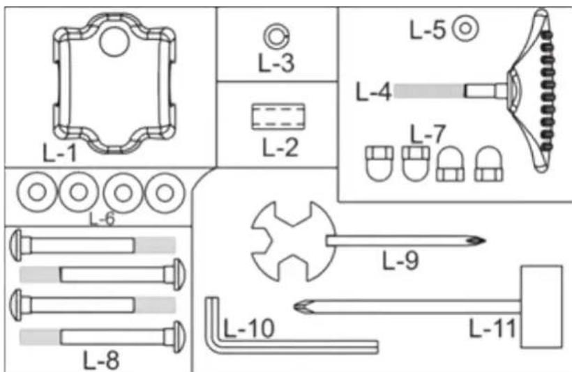
| L Hardware kit 1 Set | |||
| L-1 | Handlebars cover | (ABS) 1 | |
| L-2 | Bushing | ø12xø8x25L | 1 |
| L-3 | Washer | ø8x2t | 1 |
| L-4 | T-knob | (ABS) M8xP1.25x55L | 1 |
| L-5 | Washer | ø8xø12x1t | 1 |
| L-6 | Curved washer | ø8xø19x2t | 4 |
| L-7 | Nut | M8 | 4 |
| L-8 | Screw | M8x75mm | 4 |
| L-9 | Wrench | 13/15/17 mm | 1 |
| L-10 | Allen key | 30 x 84 mm | 1 |
| L-11 | Box spanner | 13/14 mm | 1 |
Hardware set:
Set-up:
For the assembly of this item we recommend to use the provided tools. Before starting to assemble please check according to the part-list in this manual, if all parts are complete. Perhaps some parts are already pre-assembled for your convenience. For your safety in some cases lock nuts were used. Maybe it is a little difficult to screw them tightly onto the respective screws, but they will not get loose easily (to ensure a safe connection). If you should loose and fix those lock nuts several times, they will lose this lock mechanism.
In this case you should use new lock nuts of same size.
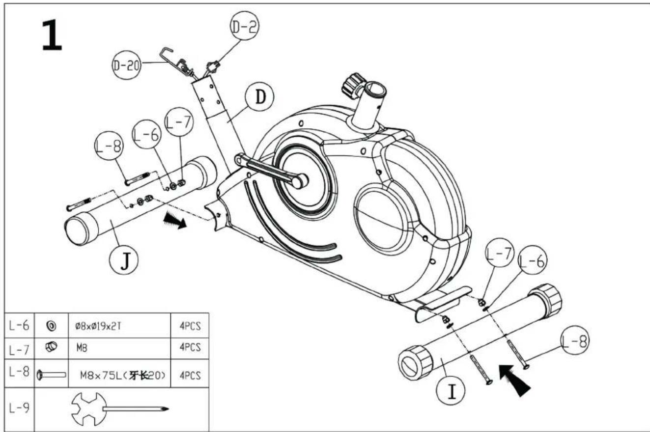
Step 1: Stabilizers
Attach the front stabilizer (J) & rear stabilizer (I) to the main frame (D) with 2 screws M8x75 (L-8), 2 curved washers 8mm (L-6) and 2 nuts (L-7). Properly fix the stabilizers in order to avoid loosing them during exercise. The rear stabilizer is equipped with adjustable endcaps (I-1) for compensation of uneven floor if necessary. Adjust these endcaps until the unit is standing firmly on the floor.
The front stabilizer is equipped with transportation rolls (J-1), which allow you to move the item easily from one place to another after assembling (please pay attention to protect your floor against scratches and/or abrasion before any transport action).

SET-UP
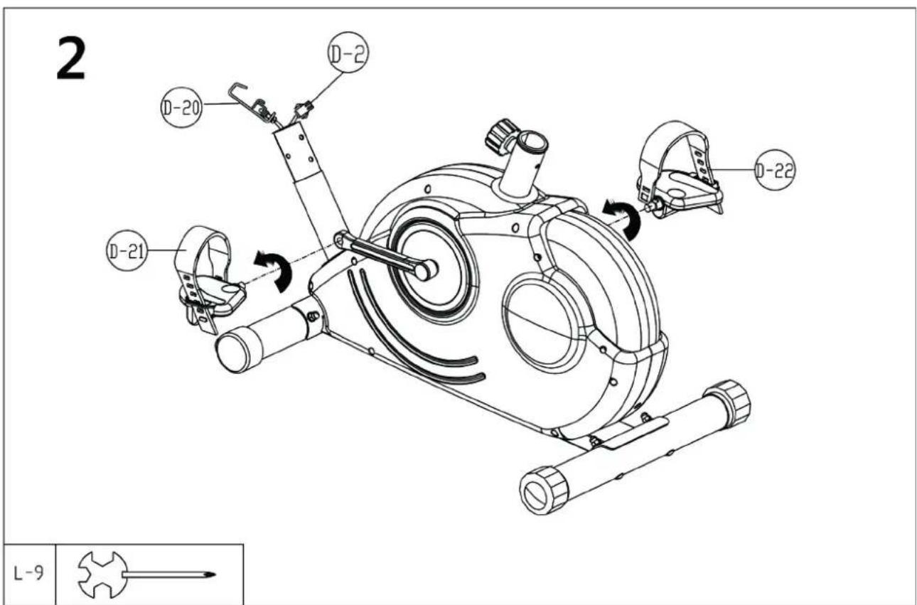
Step 2: Pedals
Screw in both pedals (D-21/D-22). The right pedal (D-22), which is marked with „R“ needs to be screwed in clockwise direction. The left pedal (D-21) needs to be fixed on the left side by screwing it in anti-clockwise direction. It is important to assemble the correct pedal on the correct side to avoid cross threading and damaging the pedal windings.
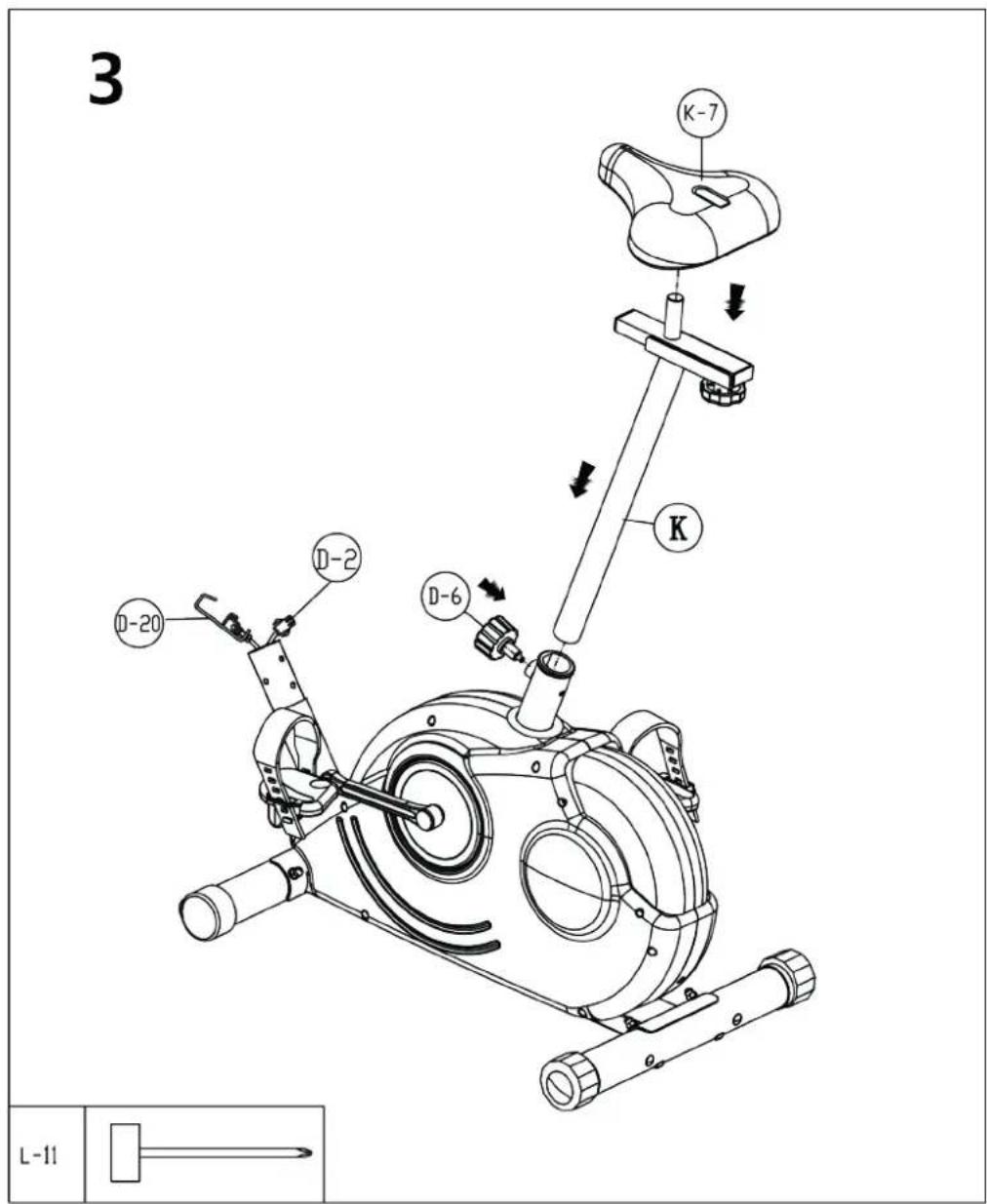
Step 3: Seat
Fix the seat (K-7) onto the seat slider (K-6) as per the drawing above. The seat can be adjusted horizontally according to your personal need (arm- and leg-length) by loosing and pulling out the knob (K-1), sliding the seat slider (K-6) to the desired position and fixing the knob (K-1) again properly. Loose the pop pin (D-6) on the main frame and slide the seat post (K) onto the rear stem of the main frame and secure with the pop pin (D-6) in a proper height. The seat should be adjusted up and down, backward and frontward to fit users personal needs. Properly fix the above connections in order to avoid injuries caused by a loose seat.

How to use the pop pin (D-6):
The seat support tube can be fixed at various heights by loosing and pulling out the pop pin (D-6), adjusting the support tube to the desired height and then fix the pop pin again properly through one of the drilled holes. Always pay attention to the markings for min. and max. height adjustments on the seat post. The seating height is correct when the knee is slightly bent with the pedal vertically downwards and the foot parallel to the floor.
SET-UP
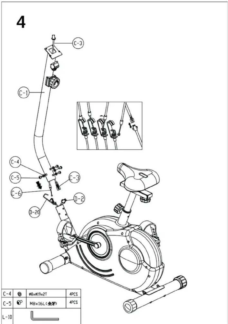
Step 4: Handlebars post and cables
Remove the pre-mounted handlebars post (C-1) by loosing the screws (C-4 / C-5). Connect both parts of the tension cable (C-6 & D-20) as shown in the small drawing. If present, remove the safety clip before. Now connect the computer cable ends (C-3 & D-2) accordingly between main frame and handlebars post (C-1). Put the handlebars post (C-1) into the main frame [be careful not to squeeze any cables!] and fix it with 4 screws M8x16 (C-5) 4 curved washers (C-4) as shown.
Hint: If the connection between the tension cable ends (C-6 & D-20) is difficult, try to manipulate the tension controller (C-6) located on the handlebar post in that way, that the upper tension cable comes out of the lower end of the post as far as possible. This makes it easier to connect the cable to the respective bottom part.
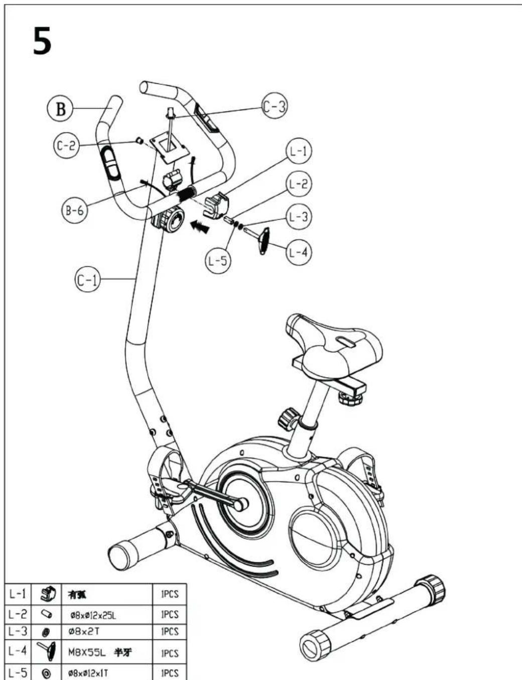
Step 5: Handlebars
Assemble the handlebars (B) to the handlebars post (C-1) by the handlebars cover (L-1), the bushing (L-2), the T-knob (L-4) and the washers (L-3 & L-5). You may adjust the angular to your individual convenience before fixing the handlebars (B) tightly. Pay attention not to squeeze the handpulse cables. Put the plastic caps onto both ends of the handlebars (if not already premounted). Guide the both handpulse cables (B-6) carefully through the drilling holes of the handlebars post (C-1).

SET-UP
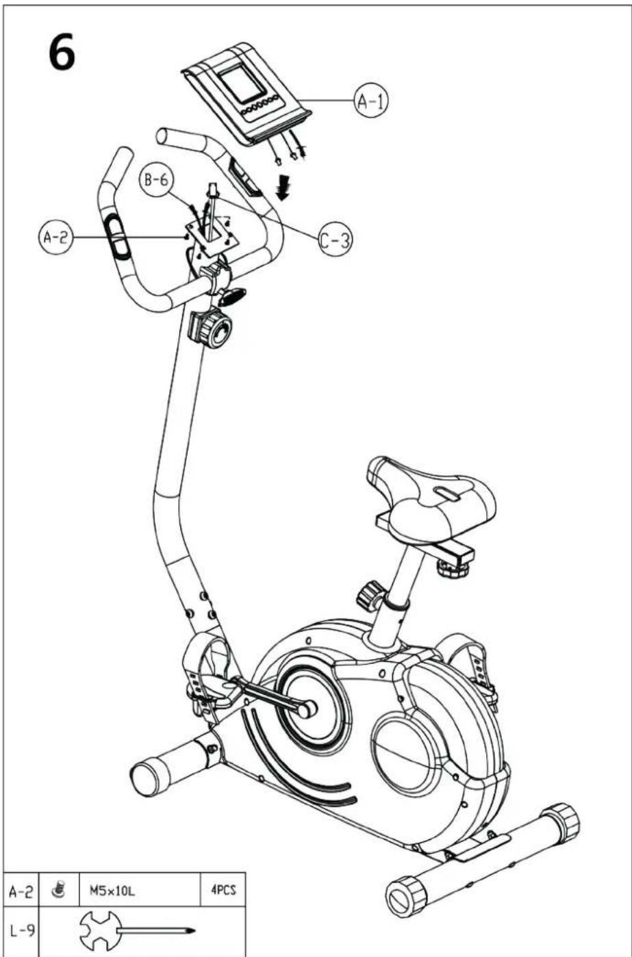
Step 6: Computer
Loose the screws M5x10 (A-2) of the computer holder. Connect the upper computer cable (C-3) and the handpulse cables (B-6) to the computer (A-1). Fix the computer (A-1) onto the holder on top of the handlebars post (C-1) as shown with the screws M5x10 (A-2).
The exercise bike is completely assembled now!
COMPUTER | USE
Computer operating instructions:
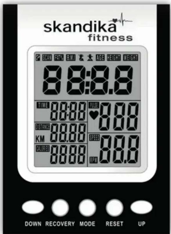

Function buttons:
UP "/DOWN To adjust values, e.g. target values
"RECOVERY" Starts the heart recovery rate measurement
,RESET To reset a value. Press and hold this button for approx. 2 seconds to execute a full reset (all values will be set to 0)
To confirm settings or select functions. This button can also be used as reset-button. Press and hold this button for approx. 2 seconds to execute a full reset (all values will be set to 0).
Before you start
Make sure the batteries are correctly inserted (please refer chapter "change of batteries"). The computer starts working by using the pedals or pressing a button. After appr. 4 minutes of getting no signal the computer shuts off to standby-mode automatically. In standby-mode room temperature and date/time will be displayed.
When switching on the computer for the first time, the date and actual time need to be adjusted. Adjust the values with "UP", "DOWN" and "MODE"-buttons.
COMPUTER | USE
After that the computer is in normal training mode and shows a display similar to this one.
You may now directly start to exercise, or you may preset target values for the functions TIME/DISTANCE/CALORIES/PULSE. When you are in each set-up mode, for example in the time set-up mode, time value is flashing, you can press "UP and DOWN" button to adjust the value and press "MODE" for confirmation. The set-up of DISTANCE, CALORIES & PULSE is the same as for TIME. If you do not want to preset value for a specific function, just set it to 0:00.
If you input several target values the computer will make a beep sound when you reach the first one of these target values. In this moment you may stop exercise or continue to exercise. If you continue, the computer will start to count up the value again.
During exercise, you may select the SCAN mode (press "MODE" until "SCAN" appears in the display). In SCAN mode, RPM/SPEED/TM/DIST/CAL/PULSE will skip to display in every 6 seconds. You can also press "Mode" button to select single function display except RPM & SPEED function. The RPM & SPEED function will always switch display.
Independently from that, the function values will be displayed in the different areas on the bottom display:
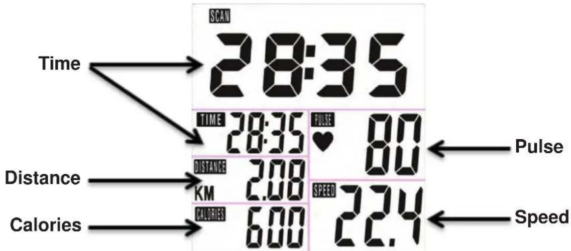
COMPUTER | USE
The function values:
The following values can be shown by the computer:
SPEED The computer shows the current speed in the display (max. 99,9km / h
TIME Computer shows actual exercise time (max. 99:59 Min).
Preset a target time:
You may preset a target time before starting a workout. The time will then count down and multiple sound beeps will be emitted when reaching 0:00. How to preset a target value, we have explained before.
DISTANCE The workout distance is displayed here (max. 99,99 km).
Preset a target distance:
You may preset a target distance before starting a workout. The distance will then count down and multiple sound beeps will be emitted when reaching 0,00. How to preset a target value, we have explained before.
CALORIES (CAL) The currently burned calories are displayed here (max. 9999 kcal).
Preset a target calorie consumption:
You may preset a target calorie consumption (kcal) before starting a workout. The calories will then count down and multiple sound beeps will be emitted when reaching 0000 kcal. How to preset a target value, we have explained before.
PULSE The computer is showing the user's heart rate in beats per minute (min. 30 / max.
240 beats per minute). For a correct display please ensure that you fully grasp the hand sensors. It may last up to 2 minutes before the pulse frequency will be measured correctly.
RPM The computer shows the current rounds/min.
Further display The computer shows room temperature, clock and date in Standby-mode.
Hints:
a) If the computer display does not show any values, please check all plug-in connections carefully to ensure that they have proper contact, and look to see whether the batteries have been inserted correctly!
b) The calorie consumption values registered and displayed with this computer merely serve as indicative values for a person of medium stature with medium resistance setting, and can deviate considerably from the actual medically precise calorie consumption.
c) The pulse values registered and displayed with this computer are merely indicative in nature and can deviate considerably from the actual pulse.
d) This computer has been tested according to the corresponding EMC standards. Even so, it is still possible for interference, in particular electrostatic discharge, to affect the display, possibly resulting in an unwanted reset or defect display. In this case, simply restart the computer (wait for it to switch off and on again) or take the batteries out briefly).
COMPUTER | USE
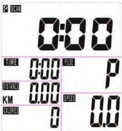
Further displays of the computer:
P^ shown in the pulse display area means, that the electrodes have not been grasped correctly. Please pay attention to all the hints given in order to gain correct pulse values. A correctly working pulse measurement is indicated by a flashing heart symbol in the display.
The display of the symbol "R" in the left upper display area means, that no training movement can be recognized by computer and therefore a training pause is present. If the symbol appears on the display during training, check all cable connections for proper installation.
If no correct measurements are possible or the display does not show correct values, please contact the customer service.
Special function: „RECOVERY“
With this special function, you can check your hearts recovery rate after a training session. This is a very important indication for the physical condition of your body. Try to improve your recovery rate with regular training sessions. The aim is, to calm down to a normal pulse frequency (frequency, when you are not in motion) as quickly as possible. To check your recovery rate, you need to keep your hands onto the hand pulse - sensors after your exercise. Now press the button "RECOVERY".
The computer will start to countdown 60 seconds. During this period the computer will constantly measure your heart rate through the hand sensors. After this minute, your recovery rate will be displayed on the display. The range is F1 to F6 (see below chart). Improve your value by intense and regular training! After the recovery function is finished, press "RECOVERY" again to return to normal operation mode. If any problems occur and you cannot return to normal computer mode, execute a complete RESET as described before.
| 1.0 | Outstanding |
| 1.0 < F < 2.0 | Excellent |
| 2.0 < F < 2.9 | Good |
| 3.0 < F < 3.9 | Fair |
| 4.0 < F < 5.9 | Weak |
| 6.0 | Poor |
BATTERY REPLACEMENT
Battery replacement
If the display quality gets poor or the pulse frequency cannot be measured correctly, you should replace the batteries. For this computer you need 2 pcs. 1.5V AA or UM3-batteries (Mignon). Pay attention to the correct polarity as marked inside the battery compartment.
Battery-Disposal
Batteries should not be considered as regular garbage. As consumer you are obliged to return finished batteries. The finished batteries can be returned to a collection base at your residential area or at places, where batteries can be bought.
WE RECOMMEND THE USE OF ALCALI-MANGAN BATTERIES.
You will find these symbols on batteries which contain harmful substances:

Pb = Battery contains lead
Cd = Battery contains cadmium
Hg = Battery contains mercury


WARNING! Battery Safety Information!
- Do not disassemble batteries!
- Clean the battery / item contact points before inserting the batteries if necessary!
- Remove discharged batteries from the device immediately!
- Increased risk of leakage, avoid contact with skin, eyes and mucous membranes! If battery acid comes in contact with any of this parts, rinse the affected area with copious amounts of fresh water and seek medical attention immediately!
- If a battery has been swallowed seek medical attention immediately!
- Replace all of the batteries simultaneously!
- Only replace with batteries of the same type, never use different types of batteries together or used batteries with new ones!
- Insert the batteries correctly, observing the polarity!
- Remove the batteries from the device if it is not going to be used for an extended period!
- Keep batteries out of children's reach!
- Do not attempt to recharge these batteries! There is a danger of explosion!
- Do not short circuit! There is a danger of explosion!
- Do not throw into a fire! There is a danger of explosion!
- Only store unused batteries in the original packing and not in reach of metallic items in order to avoid short circuit!
- Do not throw used batteries into the household refuse; put them in a hazardous waste container or take them to a battery collection point, at the shop where they were purchased!
ENVIRONMENTAL PROTECTION / EXERCISE HINTS

In the interests of Environmental Protection
At the end of its life cycle, this product must not be disposed of with household waste but must be taken to a collection unit for the recycling of electric and electronic equipment. The symbol on the product, the instructions for use or the packaging express mention of this. The basic materials can be recycled as specified on the labelling. When recycling the materials and finding other utilisation for used equipment, you are making a significant contribution towards protecting our environment.
Ask at your council about the respective local disposal sites.
Exercise hints
The following pages will inform you about some general basics about fitness training. In order to reach your personal training aims, it is absolutely necessary to read and keep in mind all the points mentioned in this user manual. In every case, it is necessary to drink enough (e.g. mineral water) during and after exercise. Thank you and we hope you will have lots of success in reaching your aims!
In order to reach perceptible improvements for your body and health, you need to pay attention to the following factors enabling you to determine the necessary training required:
1. Intensity
The intensity of your exercise has to exceed the intensity of your normal daily exertion, without reaching the point of being breathless or exhausted. A suitable coefficient for an effective workout can be your pulse-frequency. It should remain between 70% and 85% of your maximum pulse (how to calculate and find out, please check the pulse-chart in this manual).
During the first weeks the pulse should be kept in the lower range around 70% of your maximum pulse. In the following weeks and months you should continuously increase the intensity to the maximum of 85% of your maximum pulse. The better your endurance gets, the more you have to increase the training intensity. This can be reached through a longer exercise time and/or a higher load/ difficulty.
2. Frequency
Most experts recommend the combination of a healthy nutrition according to your personal exercises and 3 up to 5 workouts per week. An adult needs a minimum of 2 workouts per week to keep his/ her current constitution. 3 or more workouts will increase your personal fitness grade.
3. Organization of your workout session
Each workout session should consist of 3 phases: warm-up, exercise and cool-down. Always start with a warm-up, in which your body's temperature and the oxygen-flow will be increased. For this phase gymnastic exercises with a duration of 5 to 10 minutes are recommended. Some possible stretching exercises are shown on the pages before. After this the exercise phase should begin. The training intensity should be low for the first few minutes and should then be increased to the final intensity for a period of 15 to 30 minutes. In order to support your blood circulation system and to prevent strains and stiffness, you should do a "cool-down phase" after the exercise phase.
In this phase light stretches and gymnastic exercises should be done for about 5 to 10 minutes.
EXERCISE HINTS
4. Motivation
The key to a successful workout is regularity. We recommend, that you organize your training plan in the way, that you arrange a fix place and time for each workout day. You should also prepare mentally for your exercises. Begin your workouts only if you are in a good mood.
If you keep exercising continuously you will improve step by step.
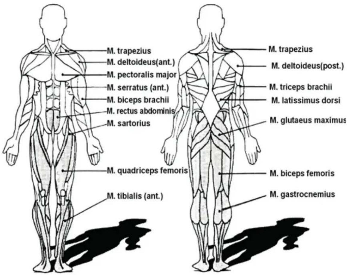
Stretching exercises for the leg-muscles
The stretching exercises on the following page are suitable for warm-up AND cool-down phase. The difference is the way of doing the stretches in these both phases.
In the warm-up phase the stretches should only be held in the extended position for app. 5 to 10 seconds (short stretching) and then the stretch needs to be released again.
This will increase the muscular tension and prepare the muscle for the coming exercise.
In the cool-down phase the stretches should be hold for at least 30 seconds in order to lower the muscular tension after your exercise and beware from stiffness.
In general you should never stretch too hard. If you should feel pain, immediately stop the stretching movement and pay attention that you will stretch only that far, that you will not feel any pain for future exercise.
EXERCISE HINTS
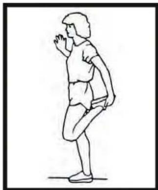
Exercise 1: Quadiceps Stretch
With one hand against a wall for balance, grasp your foot as shown and stretch the front upper muscles of the leg. Raise your heel as close as possible to the buttocks (but only so far, that you do not feel any pain). In the "warm-up" phase please hold the stretched position for 5 up to max. 10 seconds. In the "cool-down" phase you need to hold this stretch for at least 30 to 40 seconds. Please repeat min. 2 times for each leg.
Exercise 2: Inner Thigh Stretch
Seat on the floor and put together both feet-soles. Your knees are pointing outward. Pull your feet as close as possible (without feeling any pain) toward yourself and press down your knees at the same time. Never use your hands to press down the knees! Hold the stretch for app. 5 to 10 seconds (Warm-up) and min. 30 seconds (Cool-down). Repeat twice.
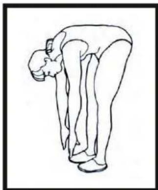
Exercise 3: Toe Touches
Stretch of gastrocnemius and biceps femoris)
Stand straight and slowly bend forward from your waist, Letting your back and shoulders relax as you stretch toward your toes. Reach down as far as you can and hold for 5 to 10 seconds in warm-up phase and 30 to 40 seconds in cool-down phase. Repeat 2 or 3 times.
Exercise 4: Stretching the back side parts of the legs
Seat on the floor and bend one leg to the inside as you keep the other leg extended. Bend forward and try to touch the foot of the extended leg. More experienced athletes should try to grasp the foot fully and point their toes to the back. This will also stretch the gastrocnemius. Again hold the stretch for 5to 10 seconds in warm-up phase and 30 to 40 seconds in cool-down phase. Repeat twice for each side.


Pulse-chart:
x-Axle = Age in years from 20 up to 70; y-Axle = Heartbeats per minute from 100 up to 220
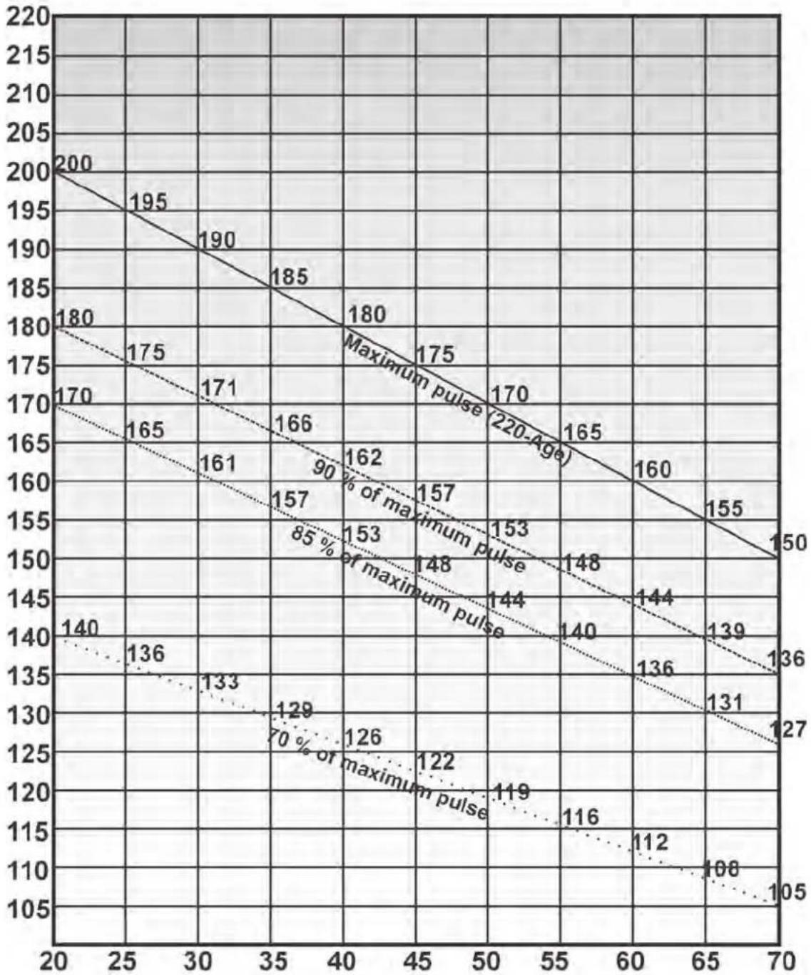
Formulas: Maximum pulse = 220 - Age 90% of maximum pulse = (220 - Age)× 0,9 85% of maximum pulse = (220 - Age)× 0,85 70% of maximum pulse = (220 - Age)× 0,7
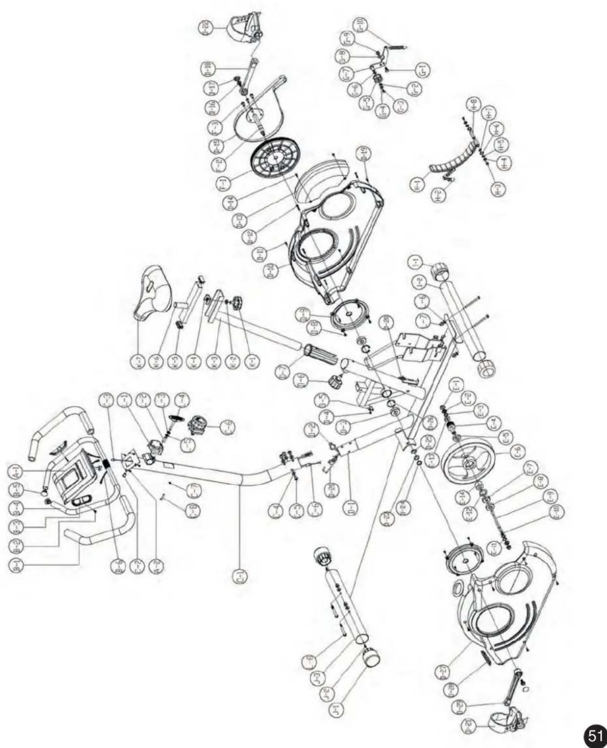
SET-UP DRAWING
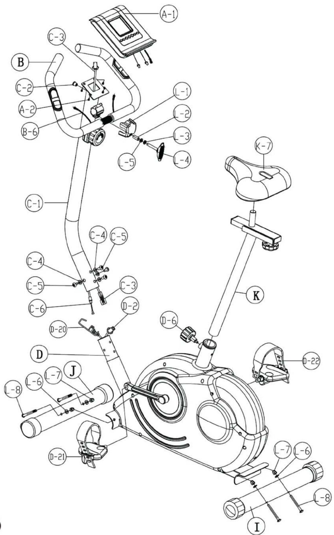
EXPLOSION DRAWING
In case of mechanical problems use this explosion drawing. All parts are marked with a specific part number in it. Tell us this number in order to replace the respective part (within warranty time this service may be free of charge).
If necessary, you may additionally use the free user manual in pdf-format, available on www.skan-dika.com. You may enlarge the explosion drawing there with a factor up to 500% .

CARE / WARRANTY TERMS
We recommend checking all parts which may get loose (screws, nuts etc.) on a regular base (e.g. all 2 or 4 weeks, this depends also on how often you use the item) for tight seating. This avoids possible injuries because of loose parts. If you want to clean this item, do not use any detergents. We recommend cleaning all parts with a smooth, light wet towel only. Please pay attention that no liquids will come in contact with the inner parts of the item or the computer, as this may lead to defects.
For our devices we provide a warranty as defined below.
- In accordance with the following conditions (numbers 2-5) we repair defect or damage to the device free of charge, if the cause is a manufacturing defect. Therefore, these defects / damages need to be reported to us without delay after appearance and within the warranty period of 24 months after delivery to the end user. The warranty does not cover parts, which easily break (e.g. glass or plastic). The warranty does not cover slight deviations of the product, which are insignificant for usability and value of the device and damage caused by chemical or electrochemical effects and damages caused by penetration of water or generally force majeure damage.
- The warranty achievement is the replacement or repair of defective parts, depending on our decision. The cost of material and labor will be borne by us. Repairs at customer site cannot be demanded. The proof of purchase along with the date of purchase and / or delivery is required. Replaced parts become our property.
- The warranty is void if repairs or adjustments are made, which are not authorized by us or if our devices are equipped with additional parts or accessories that are not adapted to our devices. Furthermore, the warranty is void if the device is damaged or destroyed by force majeure or due to environmental influences and in case of improper handling / maintenance (e.g. due to non-observation of the instruction manual) or mechanical damages. The customer service may authorize you to replace or repair defective parts after telephone consultation. In this case, the warranty is not void.
- Warranty services do not extend the warranty period nor do they initiate a new warranty period.
- Further demands, especially claims for damages which occurred outside the device, are excluded as long as a liability is not obligatory legal.
- Our warranty terms - which cover the requirements and scope of our warranty conditions - do not affect the contractual warranty obligations of the seller.
- Parts of wear and tear are not included in the warranty.
- The warranty is void if not used properly or if used in gyms, rehabilitation centers and hotels. Even if most of our units are suitable for a professional use, this requires a separate agreement.
For service, accessories and spare parts, please contact: info@skandika.com
Service centre: MAX Trader GmbH, Wilhelm-Beckmann-Straße 19, 45307 Essen, Germany