Zelos SF1850 - Exercise bike Skandika - Free user manual and instructions
Find the device manual for free Zelos SF1850 Skandika in PDF.

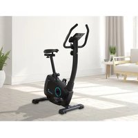
| Product Type | Exercise Bike |
| Brand | Skandika |
| Model | Zelos SF1850 |
| Maximum User Weight | 150 kg |
| Dimensions (approx.) | 100 x 50 x 130 cm |
| Net Weight (approx.) | 35 kg |
| Power Supply | Mains adapter (included) |
| Display | Time, speed, distance, calories, pulse, RPM, watts |
| Training Modes | Manual, 12 programs, user, HRC, watt |
| Resistance | Magnetic, adjustable via Up/Down keys |
| Pulse Sensors | Integrated in the handles |
| Recovery Function | Yes (Recovery) |
| Bottle Holder | Included |
| Pedals | Standard, with adjustment |
| Seat | Adjustable in height and horizontally |
| Handlebar | Adjustable, with sensors |
| Assembly | Requires assembly (tools included) |
| Maintenance | Clean with a damp cloth; check screws |
| Warranty | 24 months (defective parts) |
| Customer Service | info@skandika.com / MAX Trader GmbH, Germany |
Frequently Asked Questions - Zelos SF1850 Skandika
User questions about Zelos SF1850 Skandika
0 question about this device. Answer the ones you know or ask your own.
Ask a new question about this device
Download the instructions for your Exercise bike in PDF format for free! Find your manual Zelos SF1850 - Skandika and take your electronic device back in hand. On this page are published all the documents necessary for the use of your device. Zelos SF1850 by Skandika.
USER MANUAL Zelos SF1850 Skandika
ASSEMBLY INSTRUCTIONS and USER GUIDE

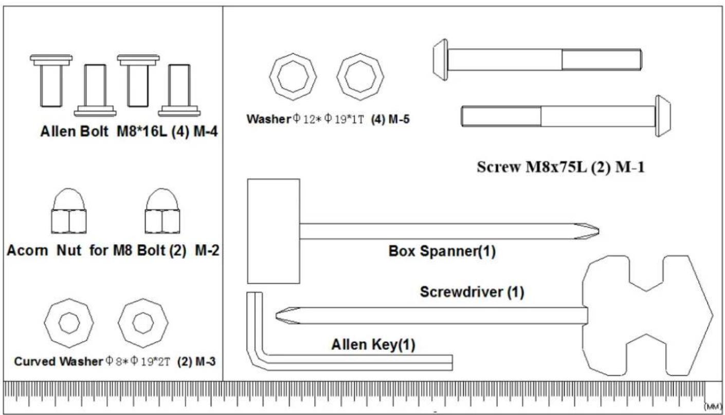
Acom Nut for M8 Bolt (2) M-2


Curved WasherΦ8Φ192T (2) M-3

Spanner(1)
(MM)
IMPORTANT SAFETY INFORMATION
This appliance only requires a small effort for assembly.
You will find all needed parts inside of the carton box.
PRECAUTIONS
WARNING: This exercise machine is built for optimum safety. However, certain precautions apply whenever you operate any exercise equipment. Be sure to read the entire manual before you assemble or operate your machine. In particular, note the following safety precautions:
-
The max. user capacity is 150 kgs.
-
This exercise machine is built for optimum safety. However, certain precautions apply whenever you operate any exercise equipment.
Be sure to read the entire manual before you assemble or operate your machine.
- BEFORE BEGINNING ANY EXERCISE PROGRAM, CONSULT YOUR PHYSICIAN.
- The pulse sensor is not a medical device. Various factors (including the user's movement), may affect the accuracy of the heart rate readings. The pulse sensor is intended only as an exercise aid in determining the heart rate frequency in general.
Before assembling
Check if all parts and tools according to the parts list in this manual are complete.
Make sure, you have a sufficient working space for proper assembly in order to avoid damages or injuries.
TABLE OF CONTENTS
Table of contents
Important Safety Information 20
Hardware Kit. 22
Parts List. 23
Drawing for Assembly 25
Exploded drawing 26
Assembly Instructions 27
Computer | Use 33
Guarantee Conditions 37
Visit our website for further information www.skandika.com

Scan the QR code with your smartphone
HARDWARE KIT
| Part # | Description Qty Part # Description Qty | |||
| A Console SM3752-67 1 D-15 Belt 1 | ||||
| A-1 Screw M5*P0.8*10L 4 D-16 Left chain cover 1 | ||||
| B Handlebar set 1 D-17 Right chain cover 1 | ||||
| B-1 | Foam grip | 2 | D-18 | Cover for handlebar post |
| B-2 | Hand pulse set | 2 | D-19 | Screw M5*16 |
| B-3 | Hand pulse wire | 1 | D-20 | Screw M4*50L |
| B-4 | Screw M4*20L | 2 | D-21 | Main frame |
| B-5 End cap | 2 D-22 Servo motor set 1 | |||
| B-6 | Handlebars | 1 | D-23 | Motor wire |
| C | Handlebars post set | 1 | D-24 | Screw M8*P1.25*20L |
| C-1 | Sensor wire (Upper) | 1 | D-25 | Semi-circular washer |
| C-2 | Screw M5*P0.8*20L | 2 | D-26 | Axle |
| C-3 | Handlebar post | 1 D-27 | Hexagonal screw M8*P1.25*12L | 3 |
| D | Main frame assembly | 1 | D-28 | Pulley |
| D-1 | Nut M8*P1.0*20L | 2 | D-29 | Bushing |
| D-2 | Knob | 1 | D-30 | Pedal set |
| D-3 | Sensor wire | 1 | E | Water bottle cage |
| D-4 | DC wire | 1 | F | Flywheel set |
| D-5 | Screw M4*10L | F-1 | Nut 3/8' | |
| D-6 | Sensor fixing bracket | 1 | F-2 | Flywheel axle |
| D-7 | Flat washer | 1 | F-3 | One-way bearing |
| D-8 | Wave washer | 1 | F-4 | Small pulley |
| D-9 | Flat washer | 1 | F-5 | Bearing 6900RS |
| D-10 | C clip | 1 | F-6 | Bearing 6003RS |
| D-11 | Bearing 6203 | 2 | F-7 | Bearing 6203 |
| D-12 | Sleeve for seat post | 1 | F-8 | Bearing 6300RS |
| D-13 | Left crank with cap | 1 | F-9 | Flat washer |
| D-14 | Right crank with cap | 1 | F-10 | Star washer |
PARTS LIST
| Part # | Description Qty Part # Description Qty | |||
| F-11 Bushing for flywheel 1 K Seat post set 1 | ||||
| F-12 Bushing for flywheel 1 L Seat slider set 1 | ||||
| F-13 Flywheel 1 L-1 Fixing screw bracket | 1 | |||
| G | Idler set | 1 | L-2 | Knob of seat |
| G-1 | Idler wheel | 1 | L-3 | Flat washer |
| G-2 | Nut M8 | 1 | L-4 | End cap |
| G-3 | Flat washer | 1 | L-5 | Seat slider |
| G-4 | Hexagonal screw M8*P1.25*18L | 1 | M | Hardware kit set |
| G-5 | Wave washer | 2 | M-1 | Screw M8*P1.25*75L |
| G-6 | Flat washer | 1 | M-2 | Nut M8 |
| G-7 | Hexagonal screw M6*P1.0*12L | 1 | M-3 | Semi-circular washer |
| G-8 | Idler spring | 1 | M-4 | Screw M8*16 |
| G-9 | Idler | 1 | M-5 | Flat washer |
| H | Magnet set | 1 | N | Switching power adapter |
| H-1 | Flat washer | 2 | O | Seat |
| H-2 | Hexagonal screw M6*P1.0*16L | 2 | ||
| H-3 | Spring washer | 2 | ||
| H-4 | Magnet | 1 | ||
| I | Front stabilizer set | 1 | ||
| I-1 | Front stabilizer pad | 1 | ||
| I-2 | Front stabilizer pad | 1 | ||
| I-3 | Screw 3/16' | 2 | ||
| I-4 | Front stabilizer | 1 | ||
| J | Rear stabilizer set | 1 | ||
| J-1 | Adjust small pad | 2 | ||
| J-2 | End cap of stabilizer | 2 | ||
| J-3 | Screw 3/16' | 4 | ||
| J-4 | Rear stabilizer | 1 | ||
DRAWING FOR ASSEMBLY
Drawing for Assembly
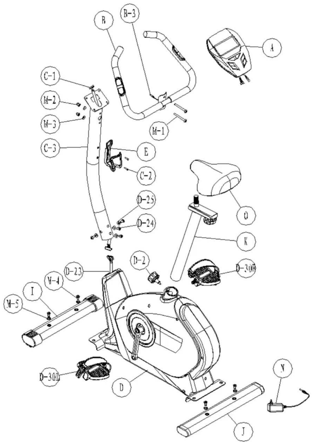
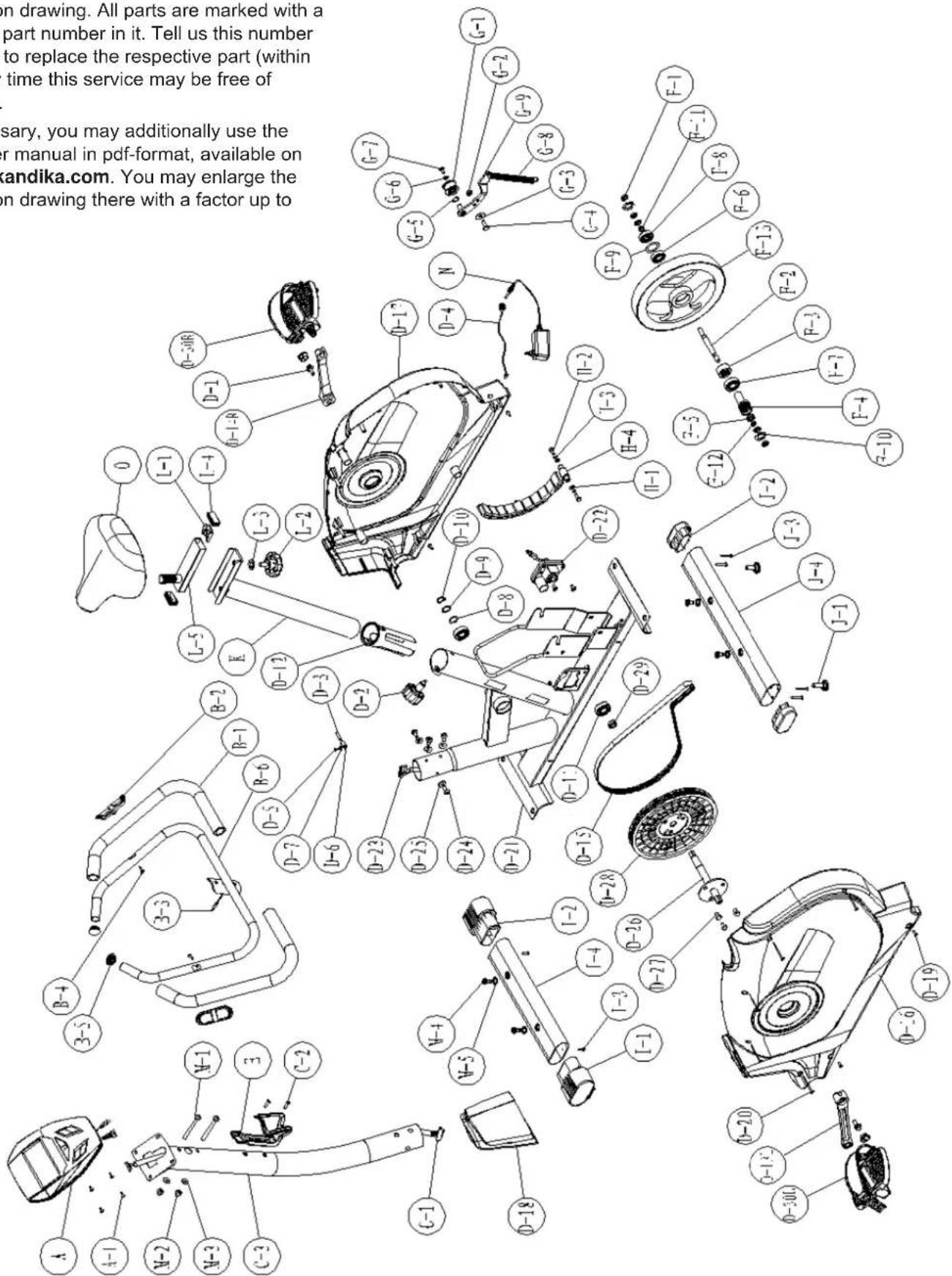
EXPLODED DRAWING
In case of mechanical problems use this explosion drawing. All parts are marked with a specific part number in it. Tell us this number in order to replace the respective part (within warranty time this service may be free of charge).
If necessary, you may additionally use the free user manual in pdf-format, available on www.skandika.com. You may enlarge the explosion drawing there with a factor up to 500% .
ASSEMBLY INSTRUCTIONS
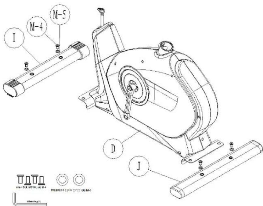
Step 1
Attach front stabilizer (I) to main frame (D) with two screws & washer (M-4, M-5). Repeat for rear stabilizer (J).
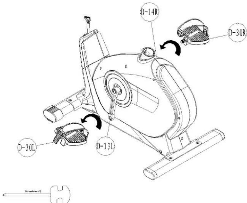
Step 2
Attach the right pedal (D-30R) onto the right crank (D-14R) and tighten it by turning it clockwise. Then attach the left pedal (D-30L) onto the left crank (D-13L) and tighten it by turning it anticlockwise. Use a wrench to attach the pedals correctly.
ASSEMBLY INSTRUCTIONS
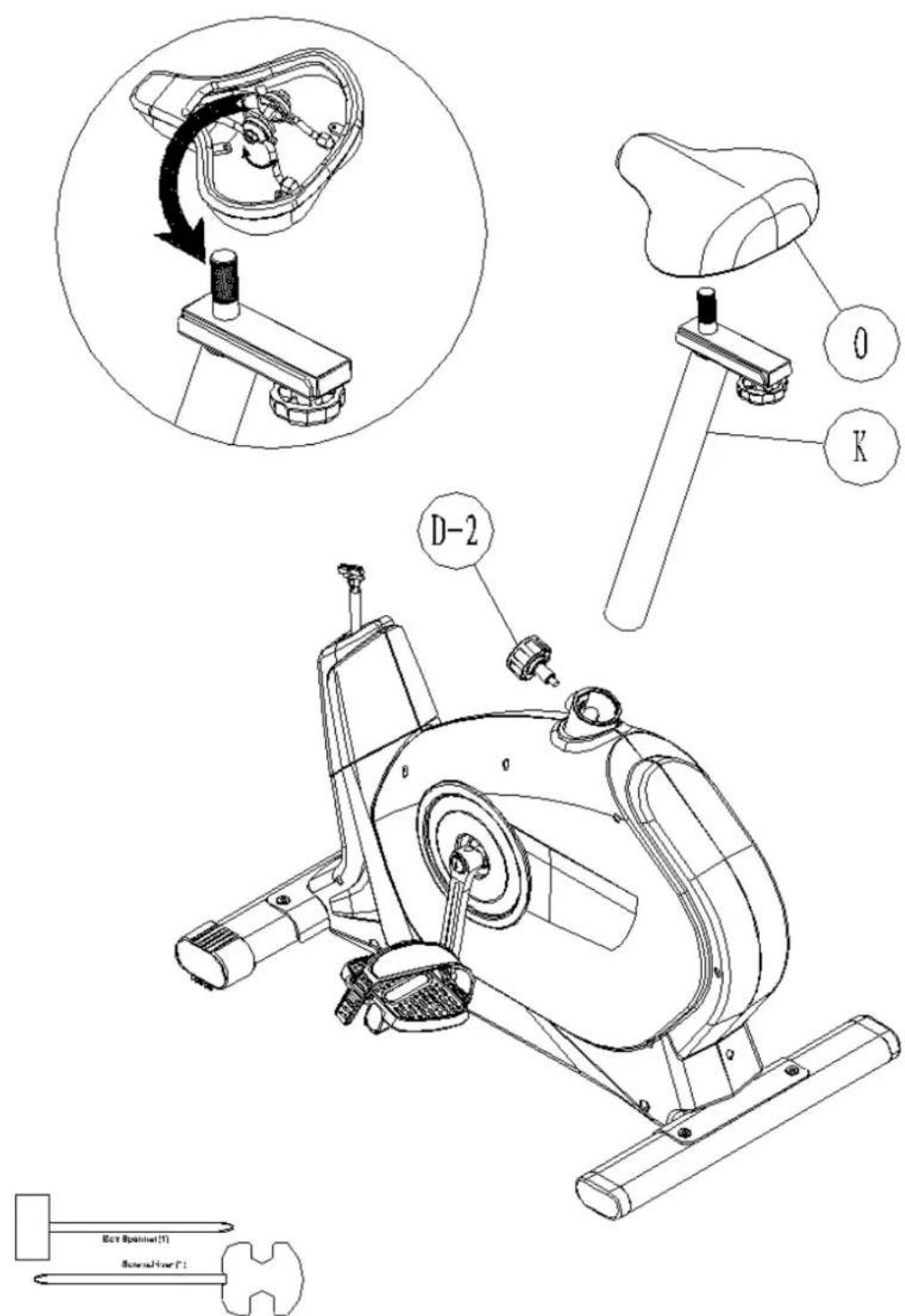
Step 3
- Assemble the seat (O) to the seat slider. The Slider can be adjusted in different angles. Tighten the two Nuts under the Seat using the provided tools. In addition, the Slider can be adjusted in horizontal level by loosening the Knob.
- Insert the seat post (K) into main frame (D) and fasten the knob (D-2) in desired position.
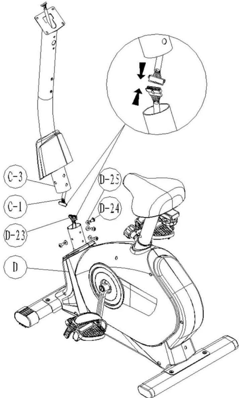
ASSEMBLY INSTRUCTIONS
Step 4
- Connect the upper sensor wire (C-1) to the motor wire (D-23).
- Insert the handlebar post (C-3) into main frame (D) and secure with screws M8 (D-24) and semicircular washers (D-25).
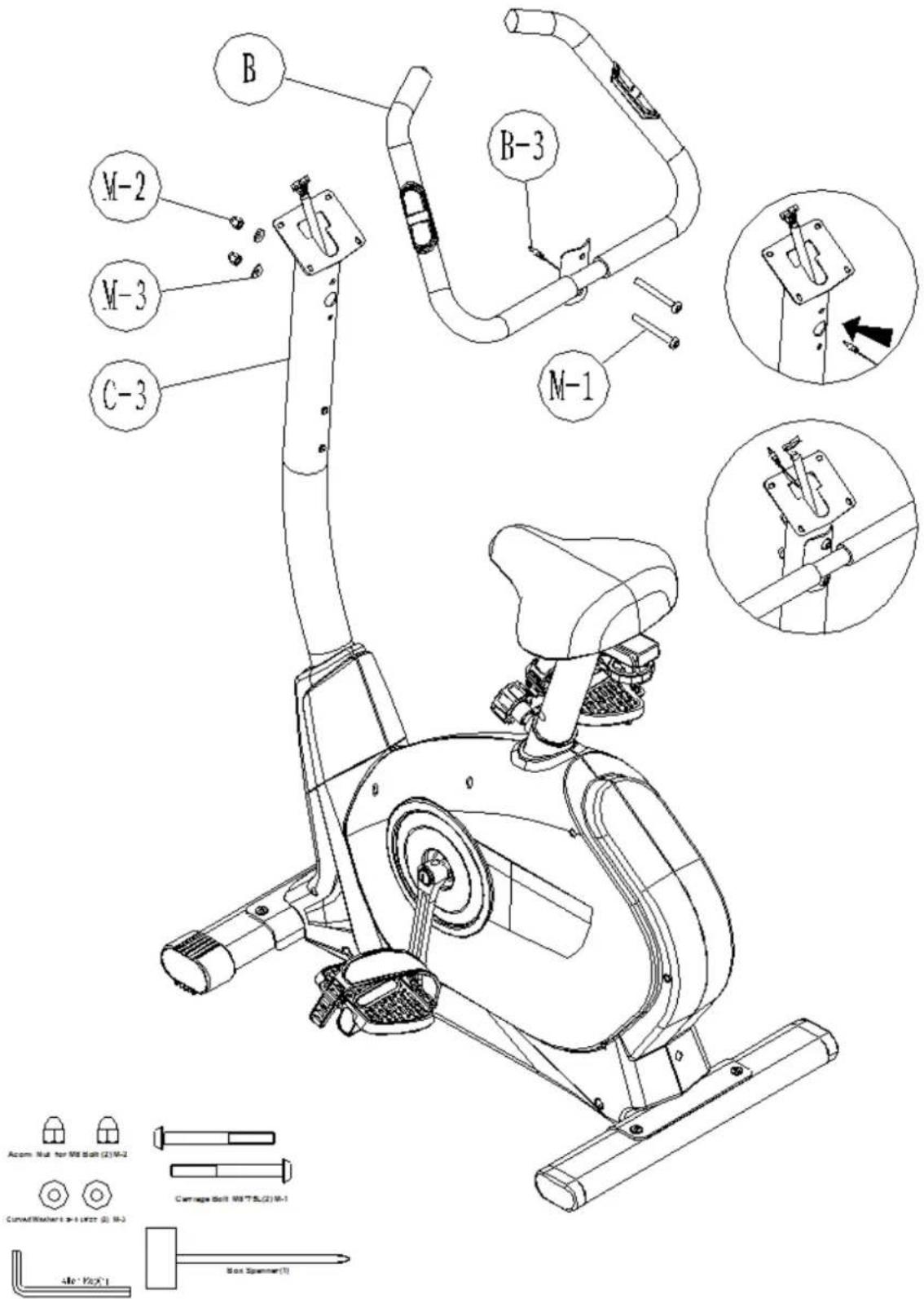
ASSEMBLY INSTRUCTIONS
Step 5
- Guide the hand-pulse wire (B-3) through the hole.
- Attach the handlebars (B) to the handlebar post (C-3) and fasten with screws (M-1), nuts (M-2) and semi-circular washers (M-3).
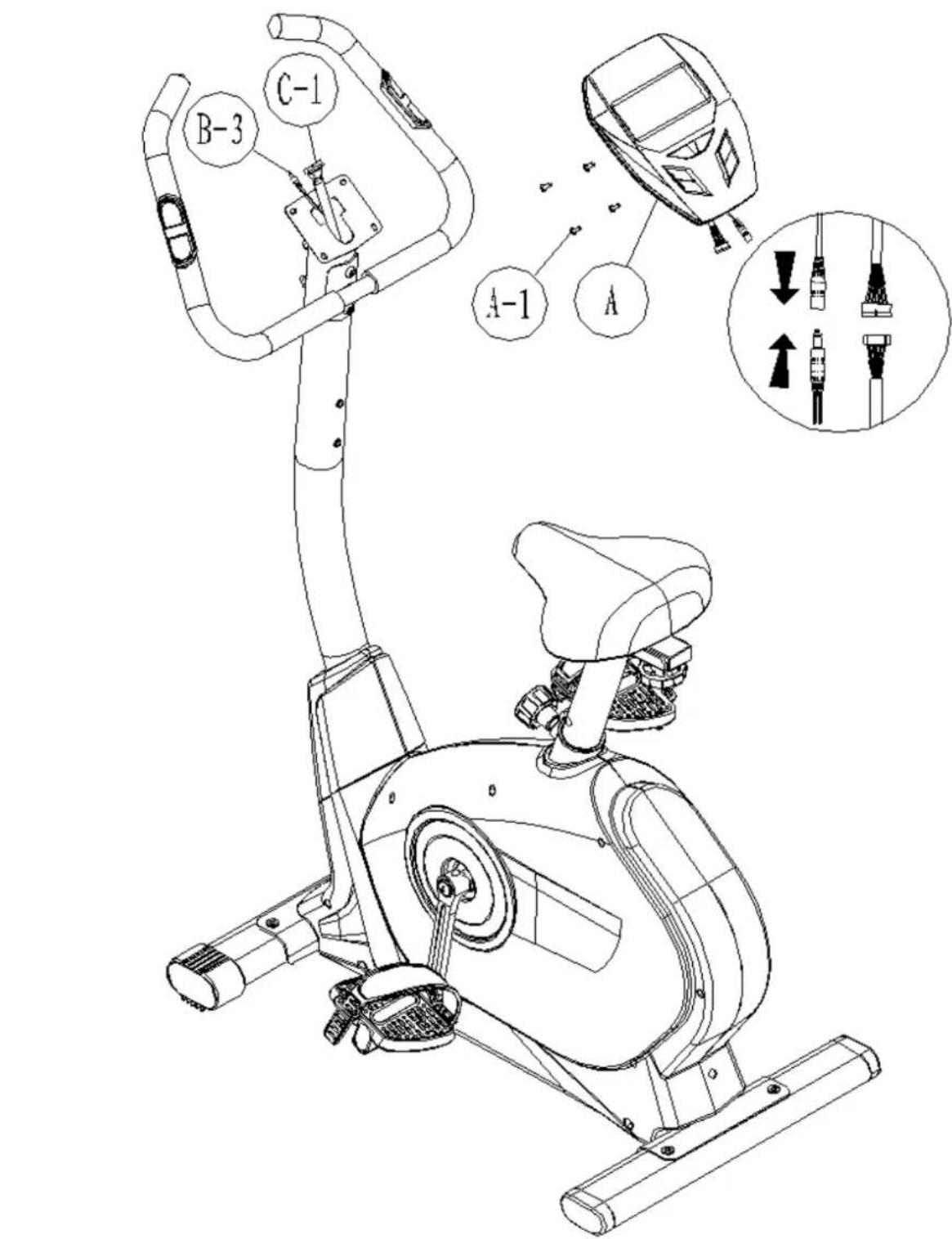
ASSEMBLY INSTRUCTIONS
Step 6
Connect the hand pulse wire (B-3) and the upper sensor wire (C-1) to the computer (A). Attach computer (A) to handlebar post (C-3) using four screws (A-1) [pre-assembled on computer].
ASSEMBLY INSTRUCTIONS
Step 7
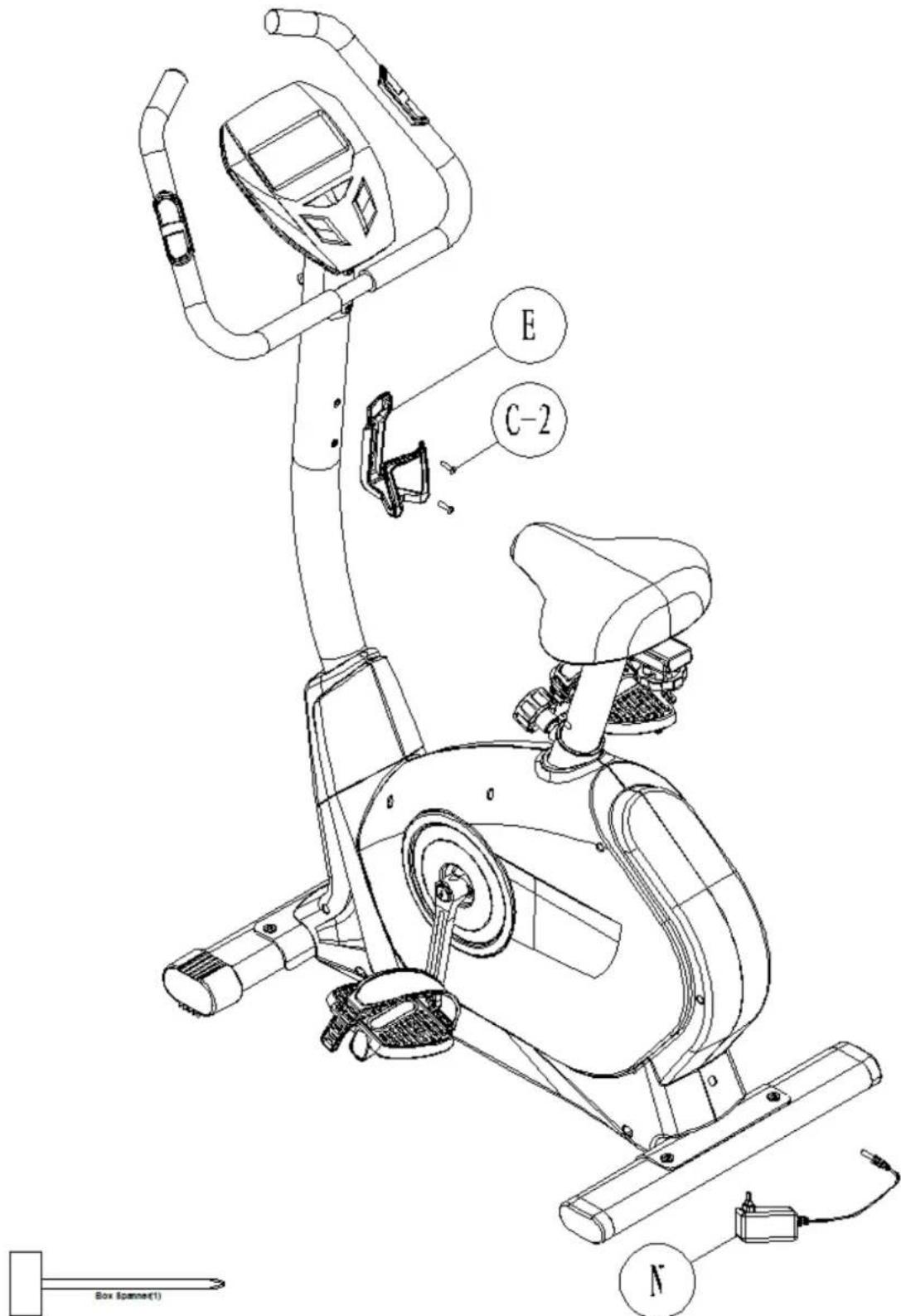
- Mount water bottle cage (E) by using screws (C-2).
- Connect the adapter (N) jack to rear part of main frame (D) as shown.
Functions
| TIME Computer shows actual exercise time (max. 99:59 Min.). | |
| SPEED The computer shows the current speed in the display (max. 99,9 km/h) | |
| DISTANCE The workout distance is displayed here (max. 99,9 km) | |
| CALORIES The currently burned calories are displayed here (max.999 kcal) | |
| PULSE The computer is showing the user's heart rate in beats per minute. For a correct display please ensure that you fully grasp the hand sensors. It may last up to 2 minutes before the pulse frequency will be measured correctly. | |
| RPM Displays the rounds per minute (max. 999 rpm) | |
| WATTS Computer shows the actual watt value (max. 350 Watt) | |
| MANUAL Manual Mode | |
| PROGRAM Program mode (12 programs) | |
| USER In this mode you can exercise according to your own programmed profiles. | |
| H.R.C. Automatically controlled training depending on your pulse frequency. | |
| WATT Watt-controlled training mode. | |
Button functions
| Up Press this button to increase the resistance during exercise. | |
| Down Press this button to decrease the resistance during exercise. | |
| Mode | Press this button to confirm any input or selection. |
| Reset | Press and hold button for min. 2 seconds to reset all data. Go back to main menu. |
| Start/ Stop | Start or Stop exercise. |
| Recovery | Press this button to start the heart recovery measurement. |
COMPUTER | USE
This computer has an automatic on/off function so that it switches on when the pedals move or when any button is pressed, and turns into stand-by mode automatically if no signal has been received for approx. 4 minutes. The computer gets its power supply by the included adaptor. The adaptor will be connected to a normal mains plug (European standard, please check the specifications resp. please use a fitting mains adaptor for your power system.
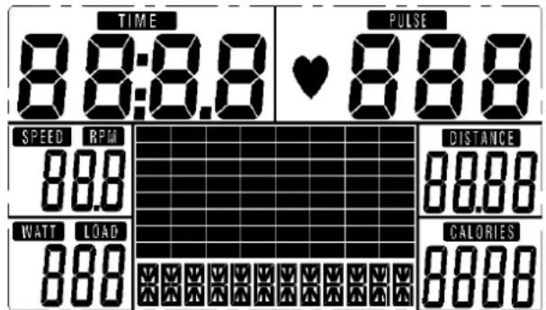
Fig.1: Full display after switching on
Manual Mode
In manual mode you can adjust the load manually.
After selecting „Manual" (confirm with „MODE"-button) you are in manual mode. Start exercise by pressing "START/STOP". You may change the tension level at any time during exercise with "UP" and "DOWN". You may also input target values for the following function values:
a. TIME / b. DISTANCE / c. CALORIE / d. PULSE
To input a target value, do not press "START/STOP" after selecting mode, but instead use "UP", "DOWN" and "MODE" to input the target values. After your input, press "START/STOP". To pause exercise, press the , START/STOP"-button at any time. If you press the Reset-button (only possible during pause mode), you may return to main menu.
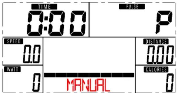
Fig.2: Manual Mode
Program Mode
You may exercise with a program profile (preset mountain- and valley courses). Choose one of the programs by pressing "UP" and "DOWN". Press "MODE" to confirm. It is also possible to enter a target time during the program training. Use the ,UP/DOWN"-buttons and "MODE" to enter a target time. You may change the tension level at any time during exercise with "UP" and "DOWN". Start exercise by pressing START/STOP. To pause exercise, press the , START/STOP"-button at any time. If you press the Reset-button (only possible during pause mode), you may return to main menu.
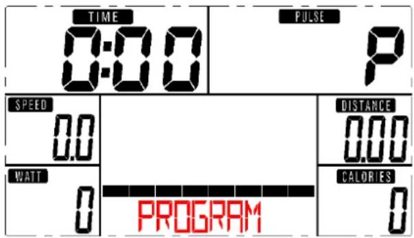
Fig.3:Programm Mode
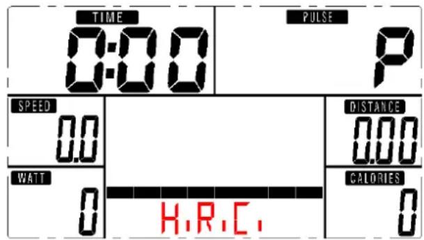
Fig.4: H.R.C.Mode
User Program Mode
In this mode you can exercise according to your own programmed profiles.
After selecting „user“ (confirm with „MODE“) you can preset each segment load (totally 20 segments) in the profile with the “UP” and “DOWN” buttons (“MODE” for confirmation). After you have finished your input, press and hold “MODE”. It is also possible to enter a target time during the program training. Use the „UP/DOWN“-buttons and “MODE” to enter a target time. You may change the tension level at any time during exercise with “UP” and “DOWN”. Start exercise by pressing START/STOP. To pause exercise, press the „START/STOP“-button at any time. If you press the Reset-button (only possible during pause mode), you may return to main menu.
H.R.C. mode (fig. 4)
You can do an automatically steered training depending on your pulse frequency. After selecting this mode and pressing MODE you are in heart frequency controlled modus. Use the „UP/DOWN“-buttons to select between 55% , 75% , 90% and direct input of the target pulse.
It is also possible to enter a target time during the program training. Use the „UP/DOWN“-buttons and “MODE” to enter a target time. Start exercise by pressing START/STOP. To pause exercise, press the „START/STOP“-button at any time. If you press the Reset-button (only possible during pause mode), you may return to main menu.
COMPUTER | USE
Watt Mode
This is the watt-controlled mode. If you preset a watt value, it is not possible to change the tension during exercise with "UP" and "DOWN" as usual because the computer will control the intensity automatically according to the target value entered. Preset a watt value with the "UP" and "DOWN" buttons ("MODE" for confirmation). It is also possible to enter a target time during the program training. Use the "UP/DOWN"-buttons and "MODE" to enter a target time. Start exercise by pressing START/STOP. To pause exercise, press the "START/STOP"-button at any time. If you press the Reset-button (only possible during pause mode), you may return to main menu.
Recovery
With this special function, you can check your hearts recovery rate after a training session. This is a very important indication for the physical condition of your body. Try to improve your recovery rate with regular training sessions. The aim is, to calm down to a normal pulse frequency (frequency, when you are not in motion) as quickly as possible. To check your recovery rate, you need to keep your hands onto the hand pulse-sensors after your exercise. Now press the button "RECOVERY". The computer will start to countdown 60 seconds. During this period the computer will constantly measure your heart rate through the hand sensors. After this minute, your recovery rate will be displayed on the display. The range is F1.0 to F6.0, whereby F1.0 is very good and F6.0 is insufficient. Improve your value by intense and regular training!
| 1.0 outstanding | |
| 1.0 < F < 2.0 excellent | |
| 2.0 < F < 2.9 good | |
| 3.0 < F < 3.9 fair | |
| 4.0 < F < 5.9 below average | |
| 6.0 poor |
NOTE
If computer shows any unusual behavior, disconnect from mains and retry after some minutes.
GUARANTEE CONDITIONS
For our devices we provide a warranty as defined below.
- In accordance with the following conditions (numbers 2-5) we repair defect or damage to the device free of charge, if the cause is a manufacturing defect. Therefore, these defects / damages need to be reported to us without delay after appearance and within the warranty period of 24 months after delivery to the end user. The warranty does not cover parts, which easily break (e. g. glass or plastic). The warranty does not cover slight deviations of the product, which are insignificant for usability and value of the device and damage caused by chemical or electrochemical effects and damages caused by penetration of water or generally force majeure damage.
- The warranty achievement is the replacement or repair of defective parts, depending on our decision. The cost of material and labor will be borne by us. Repairs at customer site cannot be demanded. The proof of purchase along with the date of purchase and / or delivery is required. Replaced parts become our property.
- The warranty is void if repairs or adjustments are made, which are not authorized by us or if our devices are equipped with additional parts or accessories that are not adapted to our devices. Furthermore, the warranty is void if the device is damaged or destroyed by force majeure or due to environmental influences and in case of improper handling / maintenance (e.g. due to non-observation of the instruction manual) or mechanical damages. The customer service may authorize you to replace or repair defective parts after telephone consultation. In this case, the warranty is not void.
- Warranty services do not extend the warranty period nor do they initiate a new warranty period.
- Further demands, especially claims for damages which occurred outside the device, are excluded as long as a liability is not obligatory legal.
- Our warranty terms - which cover the requirements and scope of our warranty conditions - do not affect the contractual warranty obligations of the seller.
- Parts of wear and tear are not included in the warranty.
- The warranty is void if not used properly or if used in gyms, rehabilitation centers and hotels. Even if most of our units are suitable for a professional use, this requires a separate agreement.
Environmental protection

At the end of its life cycle, this product must not be disposed of with household waste but must be taken to a collection unit for the recycling of electric and electronic equipment. The symbol on the product, the instructions for use or the packaging express mention of this. The basic materials can be recycled as specified on the labelling.
When recycling the materials and finding other utilisation for used equipment, you are making a significant contribution towards protecting our environment. Ask at your council about the respective local disposal sites.
For service, accessories and spare parts, please contact: info@skandika.com
Service centre: MAX Trader GmbH, Wilhelm-Beckmann-Straße 19, 45307 Essen, Germany
INFORMATIONS DES SECURITÉ IMPORTANTES

Acom Nut for M8 Bolt (2) M-2


Curved WasherΦ8Φ192T (2) M-3
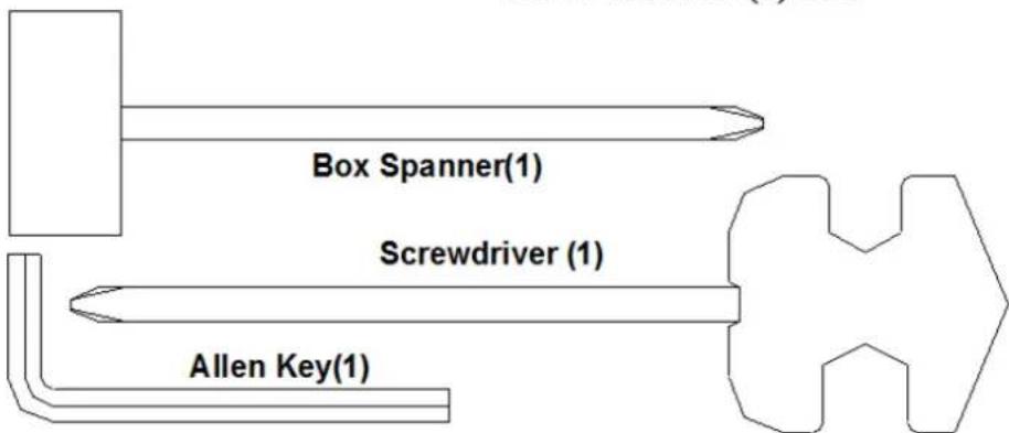
Screwdriver (1)