Supreme B - Boiler COINTRA - Free user manual and instructions
Find the device manual for free Supreme B COINTRA in PDF.

| Brand | COINTRA |
| Range / Model | Supreme B |
| Device Type | Instantaneous gas water heater |
| Fuel | Butane / Propane |
| Combustion Type | Atmospheric (natural draft, open chamber) |
| Ignition | Automatic electronic by batteries |
| Permanent pilot light | None (gas saving) |
| Flame control | Ionization |
| Gas evacuation safety | TTB device |
| Overheat protection | Automatic heat exchanger shutdown |
| Power adjustment | Selector from 50% to 100% of useful power |
| Temperature adjustment | Integrated temperature selector |
| Installation | Indoor only |
| Dimensions Supreme 11 B (H x W x D) | 595 x 295 x 195 mm |
| Flow rate variants | 11 L/min (Supreme 11 B) / 14 L/min (Supreme 14 B) |
Frequently Asked Questions - Supreme B COINTRA
- Weak batteries needing replacement
- The activation of the TTB device (exhaust problem)
- Too low water flow not activating the ignition system
- Insufficient gas pressure (almost empty bottle)
User questions about Supreme B COINTRA
0 question about this device. Answer the ones you know or ask your own.
Ask a new question about this device
Download the instructions for your Boiler in PDF format for free! Find your manual Supreme B - COINTRA and take your electronic device back in hand. On this page are published all the documents necessary for the use of your device. Supreme B by COINTRA.
USER MANUAL Supreme B COINTRA
- Carefully read and follow the instructions contained in this booklet.
- After installing the unit, inform the user about its operation and give him this manual, which is an integral and essential part of the product and must be kept for future reference.
- Installation and maintenance must be carried out by professionally qualified personnel, in compliance with the current regulations and according to the manufacturer's instructions. Do not carry out any operation on sealed adjustment parts.
- Incorrect installation or inadequate maintenance can result in damage or injury. The Manufacturer declines any liability for damage due to errors in installation and use, or failure to follow the instructions.
Before carrying out any cleaning or maintenance operation, turn off the gas by means of the special shutoff devices.
In case of a fault and/or poor operation, deactivate the unit and do not try to repair it or directly intervene. Contact professionally qualified personnel. Any repair/replacement of the products must only be carried out by qualified personnel using original replacement parts. Failure to comply with the above could affect the safety of the unit. - This unit must only be used for its intended purpose. Any other use is deemed improper and therefore hazardous.
The packing materials are potentially hazardous and must not be left within the reach of children.
The unit must not be used by people (including children) with limited physical, sensory or mental abilities or without experience and knowledge of it, unless instructed or supervised in its use by someone responsible for their safety.
The unit and its accessories must be appropriately disposed of, in compliance with the current regulations. - The images given in this manual are a simplified representation of the product. In this representation there may be slight and insignificant differences with respect to the product supplied.
2. OPERATING INSTRUCTIONS
2.1 Introduction
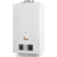
SUPREME B is a high efficiency, instantaneous domestic hot water heater using natural gas or propane gas, equipped with an open-flue burner with electronic ignition, battery powered, intended for indoor installation.
2.2 Control panel
Panel
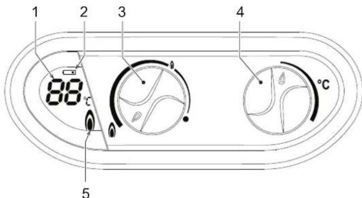
fig. 1 - Control panel
Panel - legend fig. 1
1 DHW temperature display
2 Battery level signalling
3 Burner power adjustment
4 Temperature adjustment
5 Flame symbol
Indication during operation
Table. 1 - Display symbols
| Symbol flashing: the burner is on. If the burner is off, this symbol is not displayed. | |
| Water heater outlet temperature. | |
| Symbol fixed. The battery is low. Its replacement is recommended. | |
| Symbol flashing. The battery is discharged and needs to be replaced. |
During a DHW demand (generated by drawing domestic hot water), the display shows the actual DHW outlet temperature.
2.3 Lighting and turning off
Preliminary operations and checks
- Make sure the hot water taps are closed.
- Open the water heater gas supply cock, located on its gas connection.
- Make sure the 1.5V batteries are properly fitted, with the correct polarity (+ and -). For their replacement see *** 'Replacing batteries' on page 15 ***.
- Also make sure the batteries have enough charge for water heater operation.
Lighting
Turn the knob to the required water heating level.

fig.2-Lighting
The unit will immediately be ready to operate whenever hot water is drawn.
Turning off
The burner goes off automatically when the hot water demand ceases.
No special operation is needed in order to carry out another lighting phase.
To completely shut down the unit, turn the knob to position
fig. 3 - Unit deactivated
In case of prolonged shutdown close the gas cock ahead of the unit.
For long periods of inactivity during the winter months, to avoid frost damage it is advisable to drain all the water from the water heater.
2.4 Adjustments
Manual setting of burner power
Use the power adjustment knob (ref. 3 - fig. 1) to select the water heater power, minimum or maximum and intermediate positions depending on the required water heating level. Turn the knob anticlockwise and the unit heats the water at maximum power. If the temperature is too high, for example in the summer, or when a reduced flow of not very hot water is necessary, turn the knob clockwise. This reduces the power (and gas consumption). In the position he unit is deactivated.
Temperature setting
The water temperature can be easily set with the temperature selector: turn it to the right to increase the temperature, or to the left to decrease.

fig. 4 - Temperature adjustment
Faults
After making the adjustments described above, the water heater is ready to operate in completely automatic mode. When a hot water tap is opened, an intermittent discharge is generated on the ignition electrode, which causes lighting of the burner.
All the electronic models have an ionisation electrode inserted in the burner to control correct flame presence. In case of malfunction or no gas with subsequent burner shutdown, close the hot water tap.
It is then necessary to eliminate the cause or the element preventing the gas from reaching the water heater, e.g. inadvertent closing of the gas cock, empty gas cylinder, etc.
Water heater shutdown status is deactivated by closing and opening the hot water tap.
Repeat the operation if the delivery of hot water is not restored after eliminating the cause and opening the hot water tap. If the fault persists, contact the After-Sales Technical Service.
Table. 2 - Table of faults
| - - | Temperature probe disconnected/open Temperature read by the DHW sensor < 10°C |
| EE | Probe or cable short circuited. Temperature read by the DHW sensor > 99°C |
3. INSTALLATION
3.1 General Instructions
THE WATER HEATER MUST ONLY BE INSTALLED BY QUALIFIED PERSONNEL, IN COMPLIANCE WITH ALL THE INSTRUCTIONS GIVEN IN THIS TECHNICAL MANUAL, THE PROVISIONS OF CURRENT LAW, THE NATIONAL AND LOCAL REGULATIONS, AND THE RULES OF PROPER WORKMANSHIP.
3.2 Place of installation
This unit is an "open chamber" type and can only be installed and operated in permanently ventilated rooms. An insufficient supply of combustion air to the water heater will affect its normal operation and the evacuation of fumes. Also, the fumes forming in these conditions are extremely harmful to the health if dispersed in the domestic environment.
Make sure the room where the unit is to be installed meets all the conditions required by the Current Regulations.
In any case, the place of installation must be free of dust, flammable materials or objects or corrosive gases.
Place the water heater as close as possible to the hot water taps, near the sink, but NEVER above a cooktop. It must also be located as close as possible to the flue or the place from where the fume exhaust pipe starts.

If the unit is enclosed in a cabinet or mounted alongside, a space must be provided for removing the casing and for normal maintenance operations.
3.3 Plumbing connections
Important
Before making the connection, check that the unit is arranged for operation with the type of fuel available and carefully clean all the system pipes.
Carry out the relevant connections according to the cover diagram and the symbols given on the unit.
System water characteristics
In the presence of water harder than 25^ ( 1^ = 10ppmCaCO_3 ), use suitably treated water in order to avoid possible scaling in the water heater.
3.4 Gas connection
The gas must be connected to the respective union (see figure on cover) in conformity with the current regulations, with a rigid metal pipe or with a continuous flexible s/steel tube, installing a gas cock between the system and water heater. Make sure all the gas connections are tight.
3.5 Fume duct
The diameter of the connecting pipe to the flue must not be less than that of the connection on the anti-backflow device. Starting from the anti-backflow device it must have a vertical section at least 50~cm long. The current regulations must be respected regarding the dimensioning and installation of the flues and connection pipe.

The water heater has a safely device (fume thermostat) that stops unit operation in case of poor draught or obstruction of the flue. This device must never be tampered with or deactivated.
3.6 Solar system operation mode
At the unit's cold water inlet there is a contact thermostat (set at 45^ ) for controlling the solar system water temperature. This thermostat prevents lighting of the burner when the inlet temperature is higher than the set thermostat temperature.
A thermostatic mixing valve must be installed at the DHW outlet to prevent water at high temperatures from being drawn.
The temperature of the solar system water to the unit must always be under 60^
3.7 Flue gas control device (T.T.B.)
The water heater's T.T.B. safety device ensures proper evacuation of the flue gases; therefore its operation must not be excluded and no uncontrolled operation must be carried out on it. In case of anomalies in the evacuation of flue gases, the device stops the gas supply to the burner.
If the water heater activates the T.T.B. at startup, check the burnt gas outlet, checking evacuation with a mirror cooled with water or any other device suitable for this purpose. In case of replacement, only use original spare parts.
The T.T.B. device must only be replaced by qualified personnel, proceeding as follows:
-
Remove the faulty T.T.B., loosening the two screws that secure it.
-
Fit a new original T.T.B. device.
-
Secure the T.T.B. device without forcing the screws.
-
Check proper operation.
In case of intervention of the T.T.B. stop the drawing of hot water and wait a few minutes so that the thermostat can cool down. The waiting time required depends on ambient conditions and the type of installation.
In case of repeated intervention by the T.T.B., it is necessary to eliminate the problem by taking the appropriate measures and contact the After-Sales Technical Service.
Any operation on the T.T.B. device by unqualified personnel is absolutely forbidden.
4. SERVICE AND MAINTENANCE
All adjustment, commissioning and periodical inspection operations described below must only be carried out by Qualified Personnel (meeting the professional technical requirements of the current regulations).
FERROLI declines any liability for damage and/or injury caused by unqualified and unauthorised persons tampering with the unit.
4.1 Adjustments
Gas conversion
Conversion to a gas different from the factory setting must be done by and authorised technician, using original parts and in compliance with the regulation in force in the country of installation.
The unit can work on natural gas or LPG and is factory-set for use with one of these two gases, as clearly shown on the packing and data plate. Whenever the unit has to be used with a different gas, the special conversion kit will be required, proceeding as follows:
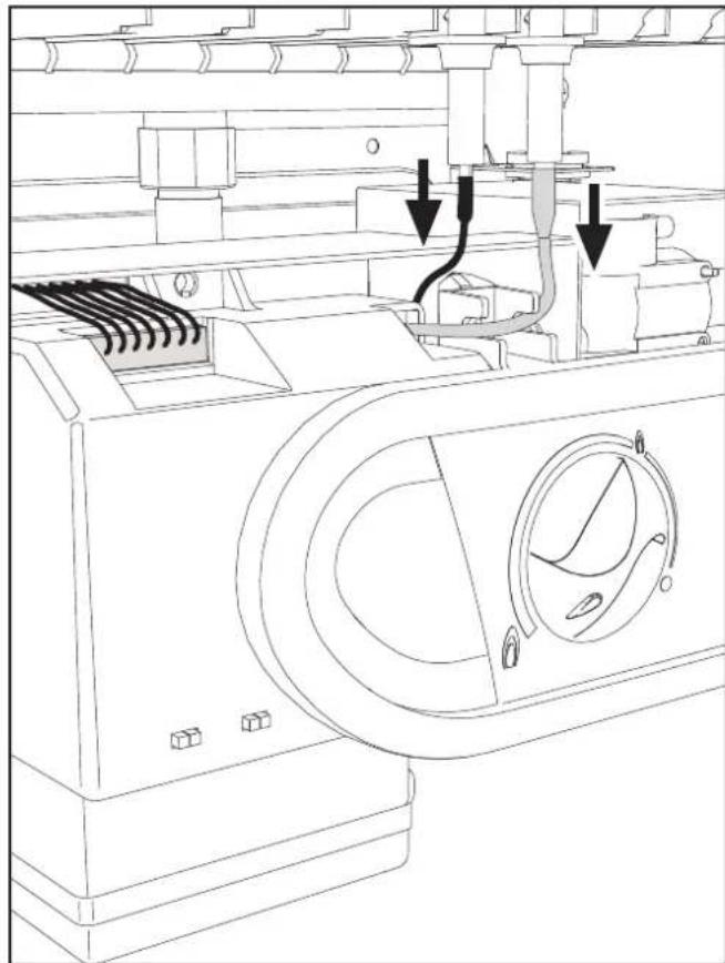
fig.5
- Disconnect the ignition electrode cable.
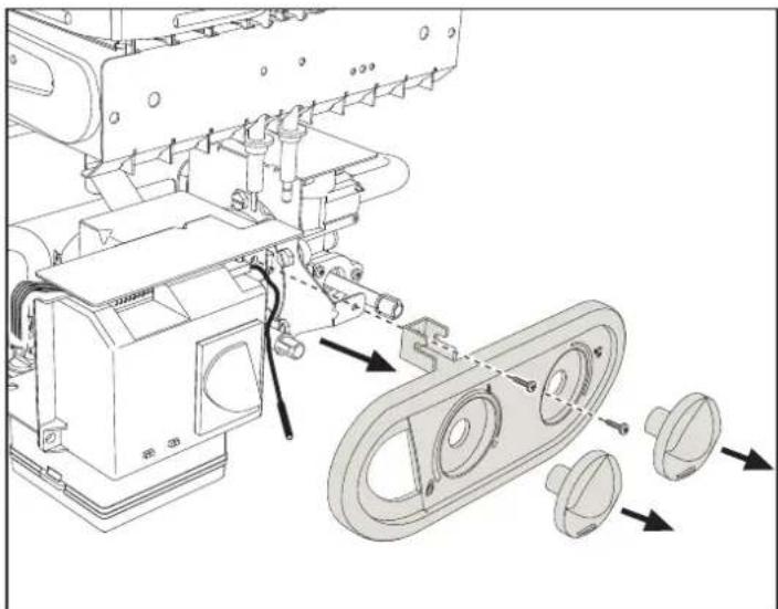
fig. 6
- Remove the adjustment knobs
- Undo the two screws and remove the cover
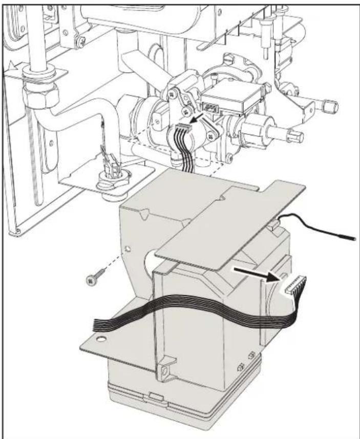
fig. 7
- Disconnect the connector of the microswitch and controller
- Undo the screw and remove the controller assembly
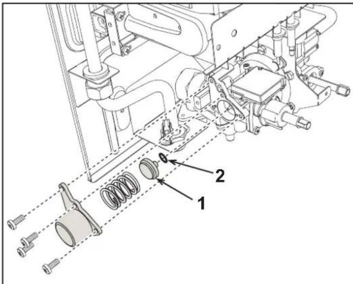
fig.8
- Undo the four modulation cone cover fixing screws.
- Remove the spring and replace the modulation cone (ref. 1 - fig. 8) with one suitable for the new type of gas, making sure the gasket (ref. 2 - fig. 8) is correctly positioned.
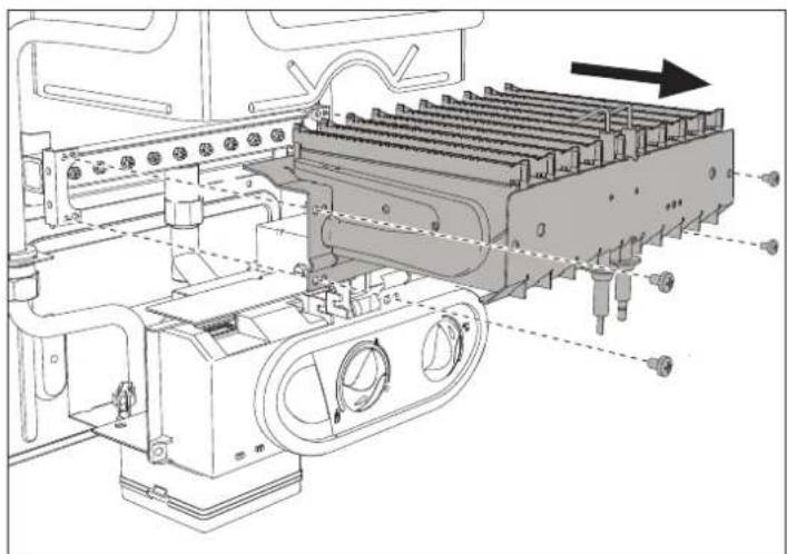
fig.9
- Undo the four burner fixing screws and pull out the tray.
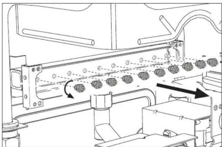
fig. 10
- Replace the nozzles at the main burner and pilot burner, fitting the nozzles indicated in the technical data table in cap. 5, depending on the type of gas used
- Apply the sticker, contained in the conversion kit, near the data plate as proof of the conversion.
4.2 Commissioning
Before lighting the water heater
- Check the tightness of the gas system.
- Fill the hydraulic system and make sure the air in the water heater and system is completely vented.
- Make sure there are no water leaks in the system and unit.
- Check the correct gas pressure value.
- Make sure there are no flammable liquids or materials in the immediate vicinity of the water heater.
Checks during operation
- Turn the unit on.
- Check the tightness of the fuel circuit and water systems.
- Check the efficiency of the flue and fume ducts when the water heater is operating.
- Check correct lighting of the water heater by turning it on and off several times.
- Make sure the fuel consumption indicated on the meter matches that given in the technical data table on cap. 5.
4.3 Maintenance
Opening the casing
To open the water heater casing:
- Undo the two screws A (see fig. 11).
- Turn the casing.
- Lift and remove the casing.

Close the gas cock upstream before carrying out any operation inside the water heater
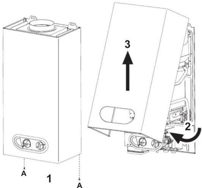
fig. 11 - Opening the casing
Replacing batteries
To replace the batteries, proceed as described in fig. 12.
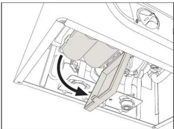
fig. 12 - Replacing batteries
Periodical inspection
To ensure proper operation of the unit over time, have qualified personnel carry out a yearly inspection, providing for the following checks:
The control and safety devices must work properly.
The fume exhaust circuit must be perfectly efficient
The fume ducts and terminal must be free of any obstacles and leaks
- The burner and exchanger must be clean and free of deposits. For possible cleaning, do not use chemical products or wire brushes.
The electrodes must be free of deposits and correctly positioned.
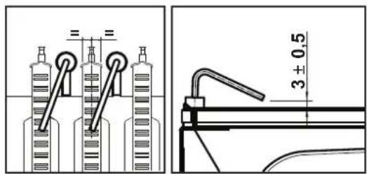
fig. 13 - Electrode positioning
The gas and water systems must be tight.
The gas flow and pressure must match that given in the respective tables.
5. TECHNICAL DATA AND CHARACTERISTICS
Table. 3 - Key of figures cap. 5
7 Gas inlet
8 Domestic hot water outlet
9 Cold water inlet
19 Combustion chamber
20 Bumer assembly
27 Copper exchanger
42 DHW temperature sensor
44 Gas valve
49 Safety themostat
78 Anti-backflow device
82 Detection electrode
83 Electronic controller
126 Contact fume thermostab
188 Ignition electrode
358 DHW inlet Solar thermostat
359 Microswitch terminal board
360 Battery compartment
5.1 General view and main components
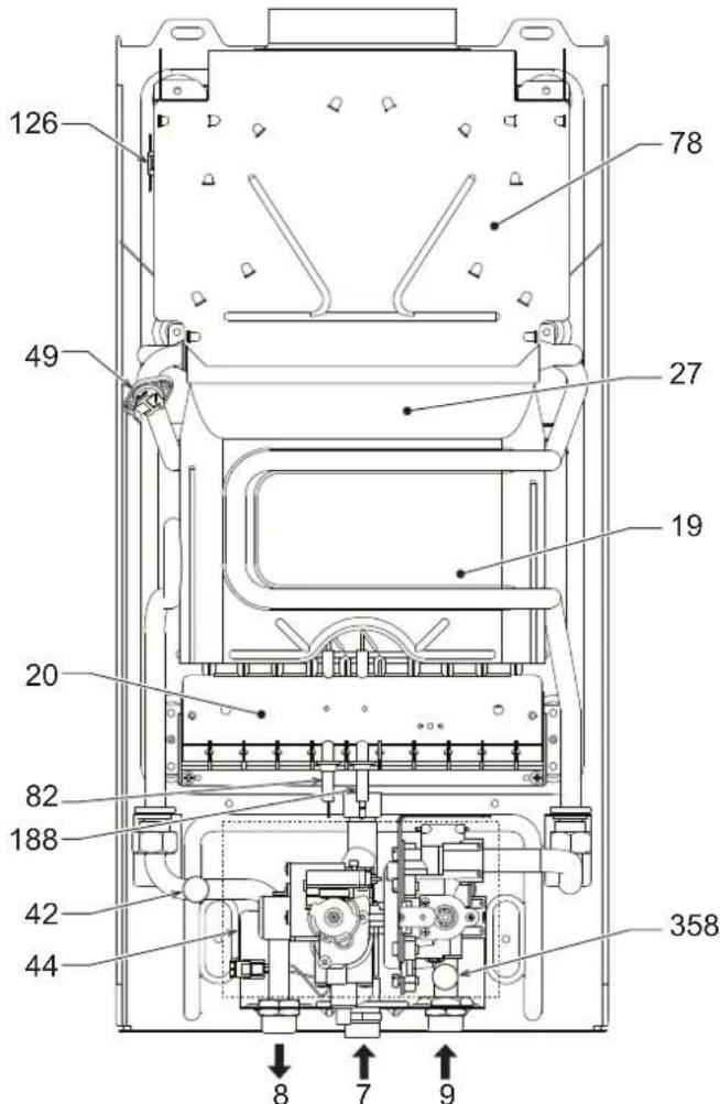
fig. 14 - General view
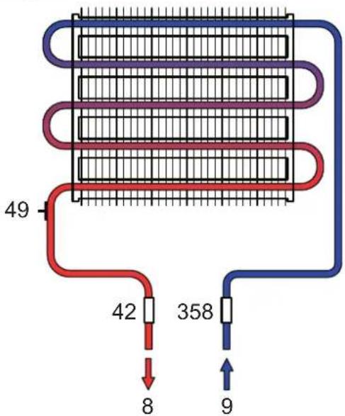
5.2 Hydraulic diagrams
fig. 15 - Water circuit
5.3 Technical data table
| Data Unit SUPREME 11 B SUPREME 14 B | ||||
| Max. heating capacity kW 21.7 26.9 (Q) | ||||
| Min. heating capacity kW 8.3 10.3 (Q) | ||||
| Max. heat output kW 19.2 23.9 (P) | ||||
| Min. heat output kW 7.1 8.8 (P) | ||||
| Efficiency Pmax | % | 88.5 88.7 | ||
| Burner nozzles G20 | no. x ∅ | 10 x 1.25 | 12 x 1.25 | |
| Gas supply pressure G20 | mbar | 20.0 20.0 | ||
| Max. gas delivery G20 | m³/h | 2.30 2.85 | ||
| Min. gas delivery G20 | m³/h | 0.88 1.10 | ||
| Burner nozzles G30 | no. x ∅ | 10 x 0.79 | 12 x 0.79 | |
| Gas supply pressure G30 | mbar | 29.0 29.0 | ||
| Max. gas delivery G30 | kg/h | 1.70 | 2.11 | |
| Min. gas delivery G30 | kg/h | 0.65 0.80 | ||
| Burner nozzles G31 | no. x ∅ | 10 x 0.77 | 12 x 0.77 | |
| Gas supply pressure G31 | mbar | 37 | 37 | |
| Max. gas delivery G31 | kg/h | 1.70 | 2.11 | |
| Min. gas delivery G31 | kg/h | 0.65 0.80 | ||
| Max. working pressure | bar | 10 | 10 | (PMS) |
| Min. working pressure | bar | 0.20 0.20 | ||
| DHW flow rate Dt 25°C | l/min | 11.0 13.7 | ||
| DHW flow rate Dt 50°C | l/min | 5.5 6.9 | (D) | |
| Protection rating | IP X5D X5D | |||
| Fume thermostat intervention temperature | °C | 90 | ||
| Empty weight | kg | 11 | 12 | |
| Type of unit | B11BS | |||
| PIN CE | 0461CL0984 | |||
| Gas category | II 2H 3+ | |||
| Fume and air flow rate | ||||||||
| SUPreme 11 B | SUPreme 14 B | |||||||
| Fume temperature at Qn (°C) | Fume flow rate | Air flow rate | Fume temperature at Qn (°C) | Fume flow rate | Air flow rate | |||
| Qn(g/s) | Qmin(g/s) | Qn(m3/h) | Qn(g/s) | Qmin(g/s) | Qn(m3/h) | |||
| G20 | 148 | 13 | 11.1 | 42 | 149 | 16.64 | 14.2 | 48 |
| G30 | 12.2 | 10.4 | 35 | 15.64 | 13.3 | 40 | ||
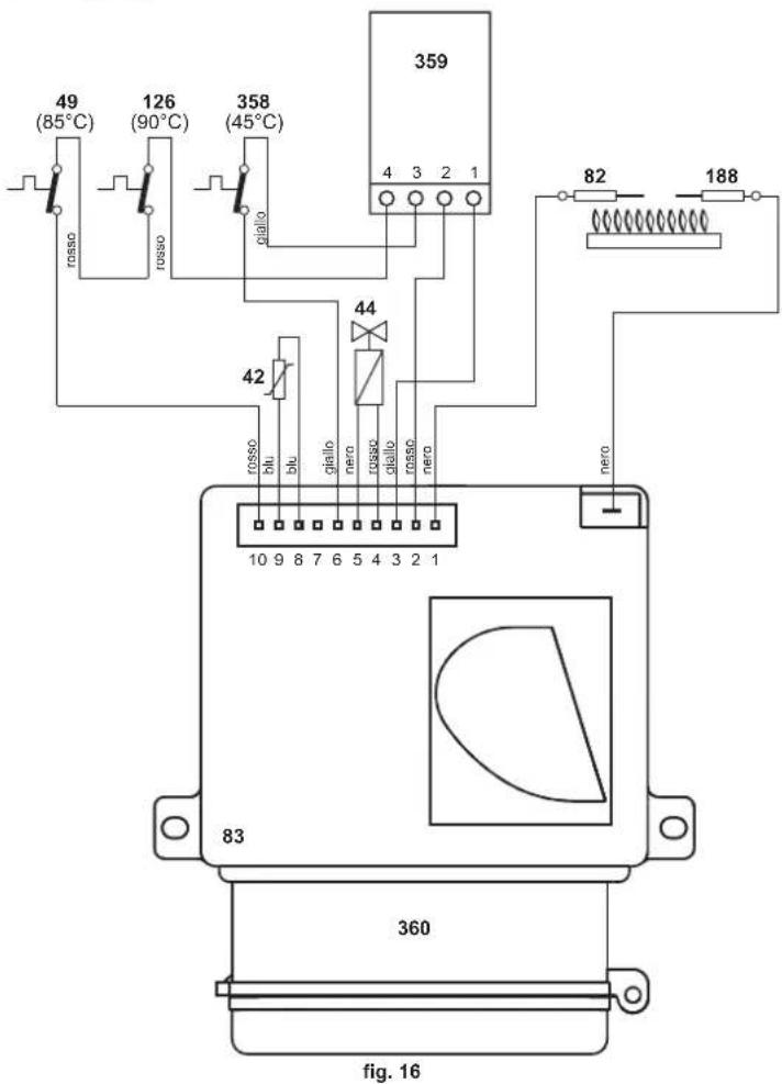
5.4 Wiring diagram
FR
1. GÉNÉRALITÉS
3.4 Raccordement gaz
EN Declaration of conformity C
Manufacturer declares that this unit complies with the following EU directives:
Gas Appliance Directive 2009/142
Efficiency Directive 92/42
Low Voltage Directive 2006/95
Electromagnetic Compatibility Directive 2004/108
EN 26 - Gas-fired instantaneous water heaters for domestic hot water production, fitted with atmospheric burners.
President and Legal Representative
Cav. del Lavoro