
CE901 Titan - Cooker Fisher & Paykel - Free user manual and instructions
Find the device manual for free CE901 Titan Fisher & Paykel in PDF.


| Product type | Built-in radiant hob |
| Brand | Fisher & Paykel |
| Model | CE901 Titan |
| Electrical supply | 8.5 kW, 220-240 V, 37 A (single-phase) |
| Product width | 914 mm |
| Product depth | 546 mm |
| Undercounter chassis height | 70 mm |
| Cutout width | 870 mm (tolerance 846-882) |
| Cutout depth | 494 mm (tolerance 486-524) |
| Cutout corner radius | 10 mm |
| Minimum clearance under countertop | 85 mm |
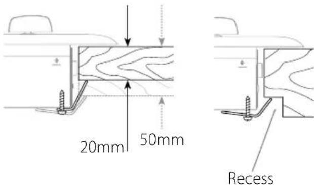
| Countertop thickness | 20 to 50 mm (with possible recess for thicker) |
| Cooking type | Electric radiant hob with hot surface indicators |
| Number of cooking zones | 5 (estimated based on dimensions) |
| Safety | Hot surface indicators, mandatory earthing, bipolar disconnection device, barrier if accessible |
| Installation | By qualified technician, compliant with local regulations, do not install above a dishwasher |
| Countertop materials | Heat resistant (tile, stone, etc.) |
| Cleaning | Smooth surfaces easy to clean, suitable wall finishes |
| Included accessories | Fixing brackets for countertop 20-50 mm |
| Documentation | User and installation manual available in multiple languages |
Frequently Asked Questions - CE901 Titan Fisher & Paykel
User questions about CE901 Titan Fisher & Paykel
0 question about this device. Answer the ones you know or ask your own.
Ask a new question about this device
Download the instructions for your Cooker in PDF format for free! Find your manual CE901 Titan - Fisher & Paykel and take your electronic device back in hand. On this page are published all the documents necessary for the use of your device. CE901 Titan by Fisher & Paykel.
USER MANUAL CE901 Titan Fisher & Paykel
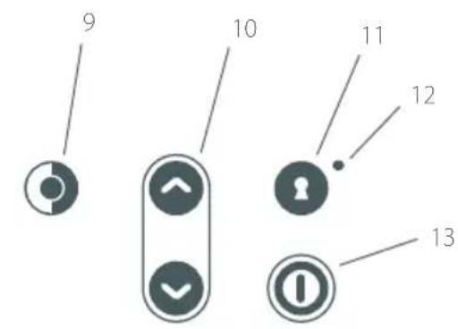
Sol X Soft Finger-Touchknapper
Copyright Reserved © Fisher & Paykel 2004.
Installation Instructions
GB Installation Information 2
DE Installationsanleitung 6
FR Instructions d'installation 10
IT Informazioni per l'installazione 14
NL Informatie voor installmentie 18
GR IAnpOopipEe EykaTaOtaonc 22
DK Installationsanvising 26
FI Asennusohjeet 30
NO Installasjonsinformasjon 34
SE Installationsinformation 38
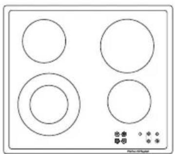
CT560QX, MX
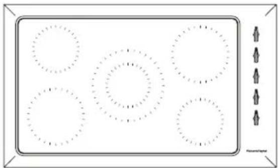
CE901
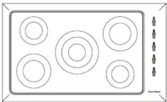
CE901M
Safety & warnings
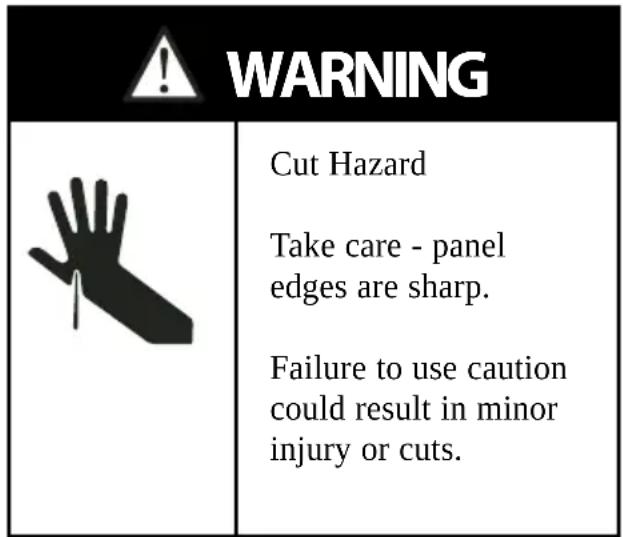

WARNING!
No combustible material or products should be placed on this product at any time.

CAUTION!
In order to avoid hazard these products must be installed by an authorised person according to these instructions.
- Failure to install the product correctly could invalidate any warranty or liability claims.
This appliance must be installed in accordance with local regulations and standards.
IMPORTANT!
- Please make this information available to the person responsible for installing the product as it could reduce your installation costs.
- Read these instructions carefully before installing or using this product.
Before you start
- Ensure the benchtop is square and level and that no structural members interfere with space requirements.
- Ensure a suitable disconnection switch is incorporated in the permanent wiring, mounted and positioned to comply with the local wiring rules and regulations. A means of disconnection with at least a 3mm air gap contact separation in all poles must be incorporated into the fixed wiring in accordance with the wiring rules, unless the local wiring rules allow for alternative means: A means of disconnection from the supply having an air gap separation in all active (phase) conductors must be incorporated in to the fixed wiring.
Make the bench top of a heat resistant material.
- Ensure there is adequate clearance between the cutout and the rear and/or side walls.
- Use easy to clean finishes for the wall surfaces surrounding the cooktop to aid removal of cooking fume staining that may result from the use of the cooktop.
- Consult local building authorities and bylaws if in doubt regarding installation.
Dimensions & clearances
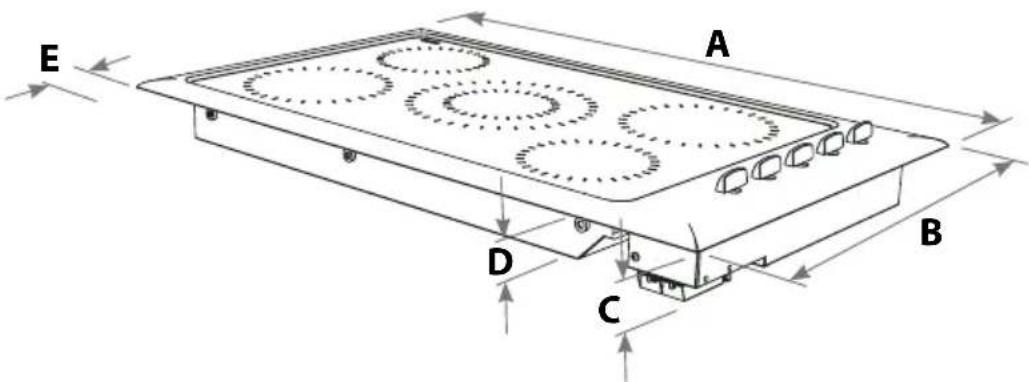
GB
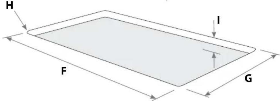
CT560QX, MX CE901 CE091M
Product
| A | Width 578 914 914 | |||
| B | Depth 511 546 546 | |||
| C | Height of terminal block under bench | - | 8 | 1 |
| D | Height of chassis under bench 60 70 70 | |||
| E | Minimum clearance from front edge of product to front edge of benchtop | - | 2 | 5 |
Cutout
| F | Width 560 (557-563) 870 (846-882) 870 (846-882) | |
| G | Depth 490 (487-493) 494 (478-501) 494 (486-524) | |
| H | Radius of all corners 10 10 10 | |
| I | Minimum clearance below benchtop | 70 85 85 |
NOTE: all measurements given in millimetres (mm) and cutout dimensions are given as a 'nominal measurement' followed by an 'otherwise acceptable range' (in brackets) e.g. for existing cutouts or replacement products.
Installation Instructions
Installation requirements (CT560 models)
If prolonged use is anticipated, or the cooktop is mounted above a drawer space, a barrier between is recommended
AND
Where the base of this product is accessible, a barrier MUST be installed to prevent contact.
If a barrier is installed below the cooktop, this barrier must be made of heat resistant material capable of withstanding sustained exposure to temperatures up to 70^ , be at least 30mm and no greater than 75mm below the base of the cooktop and have FOUR ventilation holes (min 50mm - 70mm diameter, see diagram for detail). These ventilation holes must be open to free air. It is recommended that the barrier be removable to allow ease of securing the cooktop with the supplied clamps.
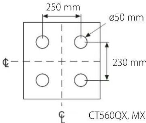
Additional requirements
- Ensure that there is a minimum of 60mm between the cutout and the rear or side wall.
If the cutout is less than 100mm from the wall, some form of protection against heat should be used, such as ceramic tiles.
The CT560 models should not be installed directly above a dishwasher as the humidity may damage the cooktop/hob electronics.
Wiring
Connect according to the label on the underside of the cooktop.
Clamping down the cooktop
This cooktop is supplied with fastening clamps that will cope with bench thickness 20-50mm. For benchtops thicker than 50mm, recess the underside to a thickness of 20-50mm.
Power Supply
CT560QX, MX 5.9kW @ 220-240V (25A)
CE901, CE901M 8.5kW @ 220-240V (37A)
Installation checklist
Please check through the following list to ensure correct installation of the product:
- Check the product is earthed.
- Check that the power cable is NOT in contact will the product. This will ensure the power cable is not damaged by heat from the product.
- Check the product is clamped down securely.
Operation checklist
- Check the product functions correctly by switching on all the elements and leaving them on for at least one minute.
While the elements are switched on, check all of the 'On' lights are functioning correctly. - Check the elements are glowing.
- Check the 'Surface Hot' indicator lights are functioning correctly by switching off all the elements. The 'Surface Hot' indicator lights should be lit and extinguish once the elements become cool enough to touch safely.
Latest information
Current installation instructions, product dimensions and specifications are also available on the Fisher & Paykel web site:
www.fisherpaykel.com

WARNHINWEIS!

Verletzungsgefahr
Installationskrav (CT560-modeller)
Checklist for installation
- Installation Instructions
- Safety & warnings
- WARNING!
- CAUTION!
- IMPORTANT!
- Before you start
- Dimensions & clearances
- Installation requirements (CT560 models)
- AND
- Additional requirements
- Wiring
- Clamping down the cooktop
- Power Supply
- Installation checklist
- Operation checklist
- Latest information
- WARNHINWEIS!
- Installationskrav (CT560-modeller)
- Checklist for installation
Brand : Fisher & Paykel
Model : CE901 Titan
Category : Cooker