
Digisight N770UA - Binoculars PULSAR - Free user manual and instructions
Find the device manual for free Digisight N770UA PULSAR in PDF.
| Product type | Night vision digital sight |
| Brand | Pulsar |
| Model | Digisight N770UA |
| Optical magnification | 4.6x |
| Magnification with digital zoom | 6.9x |
| Objective lens | 50 mm f/1.0 |
| Field of view | 4.5° angle / 7.8 m at 100 m |
| Eye relief | 67 mm |
| Exit pupil diameter | 6 mm |
| CCD matrix resolution | 500 x 582 pixels |
| Display type | LCD (640 x 480 pixels) |
| Built-in IR illuminator | Yes, laser 915 nm, adjustable power 75-100-125 mW |
| Power supply | 4 AA batteries (1.5 V) or external DC 9-15 V |
| Runtime (batteries, IR off) | 4 h |
| Runtime (batteries, IR on) | 3.5 h |
| Runtime with external power source EPS3/EPS5 | 9 h / 20 h |
| Protection rating | IP44 |
| Operating temperature range | -15 °C to +50 °C |
| Dimensions (L x H x W) | 340 x 95 x 94 mm |
| Weight with batteries | Approx. 1 kg |
| Diopter adjustment | ±4 diopters |
| Minimum focus distance | 5 m |
| Maximum detection distance (with IR illuminator) | 450 m (object 1.7 x 0.5 m, 0.05 lux) |
| Laser class (IEC 60825-1:2007) | 1 |
| Main functions | Sum Light™, Auto-contrast, digital zoom 1.5x, multiple aiming marks, wireless remote control, video output, integrated clock |
Frequently Asked Questions - Digisight N770UA PULSAR
User questions about Digisight N770UA PULSAR
0 question about this device. Answer the ones you know or ask your own.
Ask a new question about this device
Download the instructions for your Binoculars in PDF format for free! Find your manual Digisight N770UA - PULSAR and take your electronic device back in hand. On this page are published all the documents necessary for the use of your device. Digisight N770UA by PULSAR.
USER MANUAL Digisight N770UA PULSAR
natural_image
3D cutaway view of a mechanical transmission device (no visible text or symbols)DIGISIGHT
N750A|N770A|N750UA|N770UA
DIGITAL RIFLESCOPE
INSTRUCTION
ENGLISH / FRANÇAIS / DEUTSCH / ESPAÑOL / ITALIANO / PYCCKIЙ
Class 1 Laser Product
Caution - use of controls or adjustments or performance of procedures other than those specified herein may result in hazardous radiation exposure.
natural_image
Mechanical component with cylindrical body and flanged ends, no visible text or symbolsLaser aperture
| Digital Riflescope DIGISIGHT | 2-15 | ENGLISH |
| Le viseur digital DIGISIGHT | 16-29 | FRANÇAIS |
| Digitales Zielfernrohr DIGISIGHT | 30-43 | DEUTSCH |
| El visor digital DIGISIGHT | 44-57 | ESPÄNOL |
| Il Cannocchiale digitale DIGISIGHT | 58-71 | ITALIANO |
| Прицел цифровой DIGISIGHT | 72-85 | РУССКИЙ |
ENGLISH
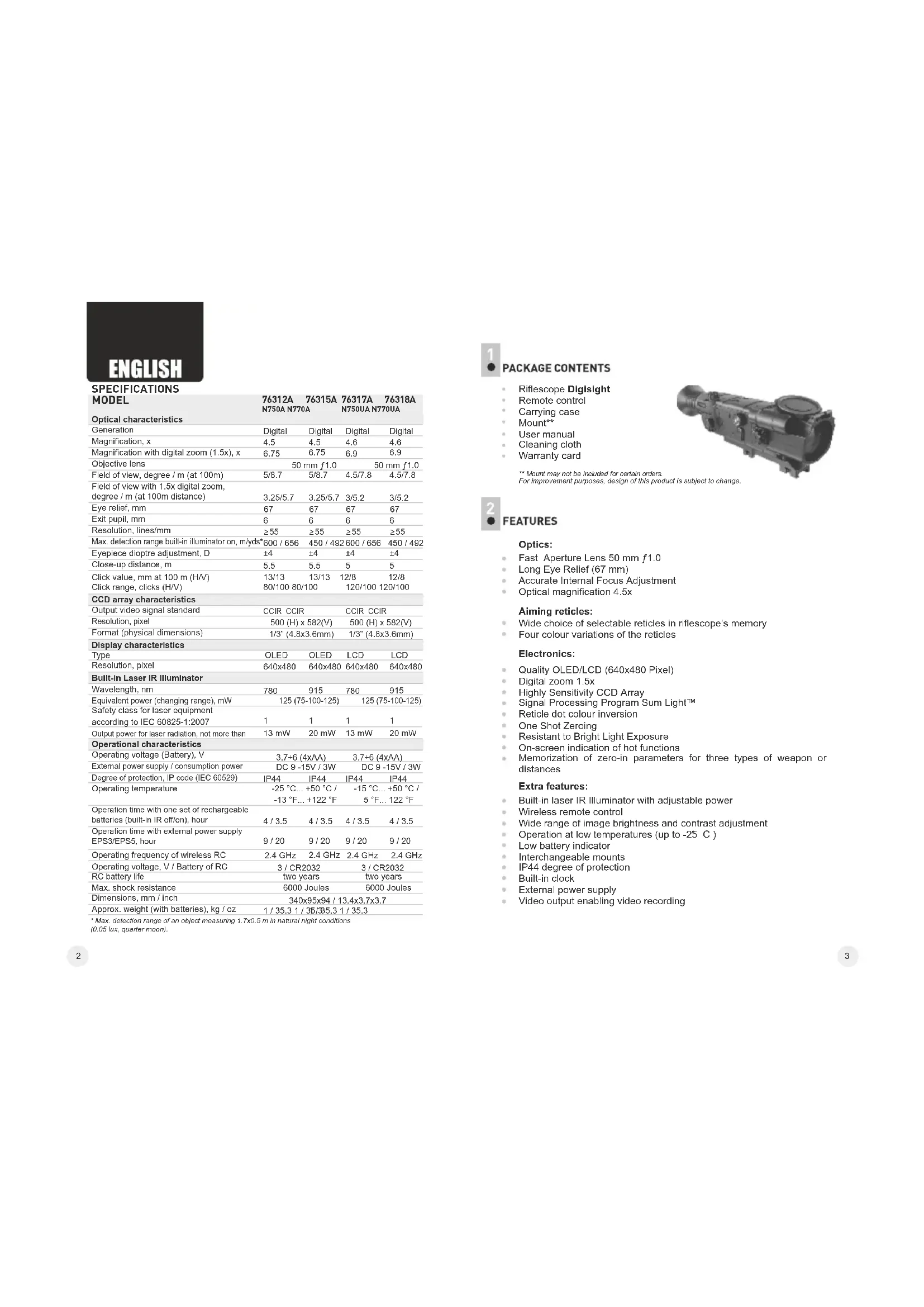
SPECIFICATIONS
| MODEL | 76312AN750A N770A | 76317AN750UA N770UA | ||
| Optical characteristics | ||||
| Generation | Digital | Digital | Digital | Digital |
| Magnification, x | 4.5 | 4.5 | 4.6 | 4.6 |
| Magnification with digital zoom (1.5x), x | 6.75 | 6.75 | 6.9 | 6.9 |
| Objective lens | 50 mm f1.0 | 50 mm f1.0 | ||
| Field of view, degree / m (at 100m) | 5/8.7 | 5/8.7 | 4.5/7.8 | 4.5/7.8 |
| Field of view with 1.5x digital zoom, degree / m (at 100m distance) | 3.25/5.7 | 3.25/5.7 | 3/5.2 | 3/5.2 |
| Eye relief, mm | 67 | 67 | 67 | 67 |
| Exit pupil, mm | 6 | 6 | 6 | 6 |
| Resolution, lines/mm | ≥55 | ≥55 | ≥55 | ≥55 |
| Max. detection range built-in illuminator on, m/yds* | 600 / 656 | 450 / 492 | 600 / 656 | 450 / 492 |
| Eyepiece dioptre adjustment, D | ±4 | ±4 | ±4 | ±4 |
| Close-up distance, m | 5.5 | 5.5 | 5 | 5 |
| Click value, mm at 100 m (H/V) | 13/13 | 13/13 | 12/8 | 12/8 |
| Click range, clicks (H/V) | 80/100 80/100 | 120/100 | 120/100 | |
| CCD array characteristics | ||||
| Output video signal standard | CCIR CCIR | CCIR CCIR | ||
| Resolution, pixel | 500 (H) x 582(V) | 500 (H) x 582(V) | ||
| Format (physical dimensions) | 1/3" (4.8x3.6mm) | 1/3" (4.8x3.6mm) | ||
| Display characteristics | ||||
| Type | OLED | OLED | LCD | LCD |
| Resolution, pixel | 640x480 | 640x480 | 640x480 | 640x480 |
| Built-In Laser IR Illuminator | ||||
| Wavelength, nm | 780 | 915 | 780 | 915 |
| Equivalent power (changing range), mW | 125 (75-100-125) | 125 (75-100-125) | ||
| Safety class for laser equipment according to IEC 60825-1:2007 | 1 | 1 | 1 | 1 |
| Output power for laser radiation, not more than | 13 mW | 20 mW | 13 mW | 20 mW |
| Operational characteristics | ||||
| Operating voltage (Battery), V | 3.7+6 (4xAA) | 3.7+6 (4xAA) | ||
| External power supply / consumption power | DC 9 -15V / 3W | DC 9 -15V / 3W | ||
| Degree of protection, IP code (IEC 60529) | IP44 | IP44 | IP44 | IP44 |
| Operating temperature | -25 °C... +50 °C / -13 °F... +122 °F | -15 °C... +50 °C / 5 °F... 122 °F | ||
| Operation time with one set of rechargeable batteries (built-in IR off/on), hour | 4 / 3.5 | 4 / 3.5 | 4 / 3.5 | 4 / 3.5 |
| Operation time with external power supply EPS3/EPS5, hour | 9 / 20 | 9 / 20 | 9 / 20 | 9 / 20 |
| Operating frequency of wireless RC | 2.4 GHz | 2.4 GHz | 2.4 GHz | 2.4 GHz |
| Operating voltage, V / Battery of RC | 3 / CR2032 | 3 / CR2032 | ||
| RC battery life | two years | two years | ||
| Max. shock resistance | 6000 Joules | 6000 Joules | ||
| Dimensions, mm / inch | 340x95x94 / 13.4x3.7x3.7 | |||
| Approx. weight (with batteries), kg / oz | 1 / 35.3 / 35/35.3 / 1 / 35.3 | |||
* Max. detection range of an object measuring 1.7x0.5 m in natural night conditions
(0.05 lux, quarter moon).

PACKAGE CONTENTS
Riflescope Digisight
Remote control
Carrying case
Mount**
User manual
Cleaning cloth
Warranty card
** Mount may not be included for certain orders.
For improvement purposes, design of this product is subject to change.
natural_image
Mechanical component with cylindrical and flanged parts, no visible text or symbols
FEATURES
Optics:
- Fast Aperture Lens 50 mm f1.0
• Long Eye Relief (67 mm)
Accurate Internal Focus Adjustment
• Optical magnification 4.5x
Aiming reticles:
Wide choice of selectable reticles in riflescope's memory
• Four colour variations of the reticles
Electronics:
Quality OLED/LCD (640x480 Pixel)
Digital zoom 1.5x
• Highly Sensitivity CCD Array
Signal Processing Program Sum Light™
• Reticle dot colour inversion
One Shot Zeroing
• Resistant to Bright Light Exposure
• On-screen indication of hot functions
- Memorization of zero-in parameters for three types of weapon or distances
Extra features:
• Built-in laser IR Illuminator with adjustable power
- Wireless remote control
• Wide range of image brightness and contrast adjustment
Operation at low temperatures (up to -25 C)
Low battery indicator
• Interchangeable mounts
• IP44 degree of protection
Built-in clock
External power supply
Video output enabling video recording

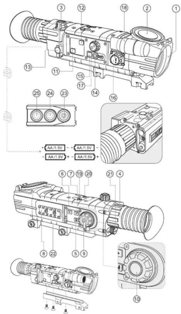
COMPONENTS AND CONTROL ELEMENTS
① Objective lens.
② Lens cap.
③ Five-position main switch (OFF-ON-IR -IR -IR).
④ Eyepiece adjustment ring.
⑤ "M" button (MENU).
⑥ "◀" button (LEFT).
⑦ “▶” button (RIGHT).
⑧ Weaver rail.
⑨ Cover of windage/elevation knob.
10 Windage/elevation knob.
⑪ "Sum Light™" button (enhanced sensitivity).
⑫ "Autocontrast" button (enhanced contrast)
⑬ "Power" jack connection to external power supply.
14 Video output.
15 Button to switch between brightness and contrast adjustment modes.
16 Lens focus knob.
17 Display brightness/contrast control knob.
18 Built-in laser IR Illuminator.
⑲ "SCR" button – digital zoom activation.
20 "INV" button - inversion of reticle's dot colour (green/red).
21 Battery compartment.
22 Mount.
Wireless remote control:
23 "ON" button.
24 "IR" button.
25 "ZOOM" button.

DATA PANEL ICONS:
| ◆ ↔ | Reticle moving directions |
| X=00Y=00 | Reticle's X and Y coordinates |
| Autocontrast mode | |
| S | SumLightTM mode |
| Brightness and contrast adjustment | |
| 00:00 AM | Clock |
| Low battery indicator | |
| Clock setup | |
| x1.5 | 1.5x digital zoom |
| IR·IR: IR: | IR Illuminator power level |
| Indication for external power supply | |
| One shot zeroing | |
| Activation of wireless remote control | |
| Limiting frame | |
| × | Auxiliary cross |
| PAL/NTSC video output signal selection | |
| Reticle selection | |
| Weapon selection |

DESCRIPTION
The Digisight is designed for observation and shooting in twilight or nighttime. In complete darkness (no stars or the Moon) use of the built-in IR (or laser) Illuminator is highly recommended. Your riflescope is a versatile device designed for a wide range of professional and amateur applications such as hunting, sports shooting, night video recording and observation.

The riflescope has been designed for long-term usage. To ensure longevity and performance, please adhere to the following:
Before use make sure that you have installed and fixed the mount according to the instructions of the section "Installation of mount".
• Store with the lens cap on in the carrying case.
• Switch off the scope after use.
• The riflescope cannot be submerged in water.
• Attempts to disassemble or repair the scope will void the warranty!
- Clean the scope's optical surfaces only if necessary, and use caution. First, remove (by blowing with a blower brush or canned air) any dust or sand particles. Then proceed to clean by using camera/lens cleaning equipment approved for use with multicoated lenses. Do not pour the solution directly onto the lens!
The riflescope can be used in various operating temperatures. However, if it has been brought indoors from cold temperatures, do not turn it on for 3 to 4 hours. This will prevent external optical surfaces from fogging.
- If the scope is unable to mount onto the rifle securely, or you have doubts about the mounting system, see a qualified gunsmith. Using the weapon with a poorly mounted scope can lead to inaccurate target shooting!
- To ensure reliable performance, it is recommended to carry out regular technical inspections of the unit.
- Do not leave batteries in the unit if it is not going to be used for an extended period (1 month or more)
- Batteries shall not be exposed to excessive heat such as sunshine, fire or the like.

INSTALLATION OF BATTERIES
• Unscrew and remove the battery cover (21).
• Install four AA batteries according to the marking on the battery compartment cap.
- Replace and screw back the battery cover tightly.
Battery charge level is displayed on the data panel (☐). In case of complete battery discharge, a red icon is flashing on the data panel and in the centre of the display.
Note: to ensure long and reliable operation it is recommended that you use quality rechargeable batteries with a capacity of at least 2500 mAh. Please do not use batteries of different types or batteries with various charge levels.

EXTERNAL POWER SUPPLY
The riflescope can be powered with an external DC power supply (2.1mm pin) with stabilised voltage ranging from 9V to 15V (max. consumption power 3W) or a 12V vehicle socket.
External power supply (AC/DC) is to be connected to "Power" (13) jack located on the right side of the device.
Note: the central pin of the power supply that you connect to the "power" jack of the riflescope, must have marking "+".
The power supply may have marking -0-+
Connection of an external power supply (icon - on the data panel) automatically cuts off power supply from batteries.
External power supply DOES NOT charge the batteries in the riflescope! Attention! We suggest that you use battery packs EPS3 or EPS5 ensuring from 9 to 20 hours of continuous operation.

OPERATION
Installation of mount
Before using the riflescope you need to install the mount.
The riflescope can be used with various mount types such as Weaver, Europrism, Los, Side mount, MAK adapter etc. that allow the scope to be installed on different types of rifles.
The mounting holes in the base of the riflescope enable the mount to be installed in one of the multiple positions. The choice of the mounting position helps the user to ensure the correct eye relief depending on the rifle type.
- Attach the mount to the base of the riflescope using a hex-nut wrench and screws (see installation scheme on page 5).
• Install the scope on the rifle and check if the position is suitable for you; - If you are happy with its position, remove the scope, unscrew the screws halfway, apply some thread sealant onto the thread of the screws and tighten them fully (do not overtighten). Let the sealant dry for a while.
The riflescope is ready to be installed on a rifle and to be zeroed.
Note: changing the mount position may require a slight re-zeroing.
Starting the scope and image setup
• Install the batteries according to the directions in Section 7 or connect an external power supply.
• Open the lens cap (2).
- Turn on the riflescope turning the selector switch (3) to the "ON" position – within a couple of seconds the display will light up.
- Adjust sharpness of display symbols with the dioptre focus knob (4). After this adjustment no further dioptre adjustment should be required, regardless of distance or other factors.
- To adjust the display brightness, rotate the knob (17). Brightness level from 0 to 20 is shown next to the icon ⭐ in the upper part of the display and then on the data panel.
- Press button (15) to switch to display contrast setup mode. Contrast level from 0 to 20 is shown next to the icon in the upper part of the display and then on the data panel.
Subsequent press of the button "INV" (20) changes colour mode of the as follows:
1st press – main part of the reticle is black, additional part is red;
2nd press – main part of the reticle is black, additional part is green;
3rd press – main part of the reticle is white, additional part is green; 4th press – main part of the reticle is white, additional part is red.
- Choose a still object that is, for instance, 100 metres away.
Rotate the lens focus knob (16) to achieve best possible image sharpness. To quickly adjust for a target 100m away, set the lens focus knob (16) opposite mark "100" on the lens focus knob.
- Warning! Focusing range may vary depending on the illuminance level in the daytime mark "100 m" on the lens focus knob equates to around 10 metres.
- To increase 4.5x magnification up to 6.8x, activate 1.5x digital zoom by pushing "SCR" (19) button.
- In low light conditions or in complete darkness turn on the built-in laser IR Illuminator (18). The IR Illuminator has three power degrees – choose the required one by turning the selector switch (3) to one of the three positions IR·IR: IR:
- When finished, turn off the riflescope by turning the selector switch (3) to the "OFF" position.
• Close the lens cap (2).

ZEROING
The riflescope features two zeroing methods - traditional zeroing and "one shot" zeroing.
Zeroing should be done at operating temperatures, by following the order of these steps:
Traditional zeroing:
• Mount the rifle with the riflescope installed on a bench rest.
• Set a target at a distance of about 100m.
- Adjust the riflescope according to the instructions of Section 9 "OPERATION".
• Aim the firearm at the target using the mechanical sight.
• Using live ammunition, take 3-4 shots, continually aiming at the same hit point on the target.
- Examine the target and determine if the aiming point coincides with point of impact, if you determine it's necessary to make corrections, you will need to adjust your aiming point.
• To do this, unscrew the knob cover (9), push the knob (10) to hear a click.
- First push of the knob enables vertical movement of the reticle ( ), appears
• on the data panel), second push enables horizontal movement (icon◇).
Another push of the knob lets you quit this mode.
- Check the accuracy of your adjustments by firing 3 or 4 control shots.
• The scope should now be zeroed-in for the specified distance.
One shot zeroing:
Follow first four steps, set forth in subsection "Traditional zeroing".
Take a shot. If the point of impact does not match the target centre push the "M" (5) to enter main menu and choose with ◀/▶ (6,7) buttons menu option "Zeroing" marked by ✉ icon.
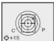
- On the right of the icon 🔒 appears icon 🔒; auxiliary cross (C) appears in the centre of the aiming reticle.
- Holding the reticle in the aiming point, by rotating the windage/elevation knob (10) move the auxiliary cross (C) horizontally or vertically relative to the reticle until the auxiliary cross matches the point of impact (P) (see pic.). To switch between movement direction push the knob (10) to hear a click. When moving directions of the reticle changes, the active coordinate changes its colour from white to red.
Note: the aiming reticle can move only within the red limiting frame (see pic.) that defines the click range - 80 clicks horizontally, and 100 clicks vertically (models 76312A/76315A); 120 clicks horizontally, and 100 clicks vertically (models 76317UA/76318UA).
- Exit the menu option "Zeroing" by holding the "M" button pressed for one second. The reticle will now move to the point of impact.
- Make another shot - the point of impact should now match the aiming point.
• The riflescope should now be zeroed-in for the specified distance.
Note: zeroing parameters (coordinates X; Y) are saved in the riflescope's memory as number 1 in the menu option "Weapon choice". If you want to zero in the riflescope using another weapon or another distance, select option 2 or 3 (details in the menu option "Weapon choice" section 11) and do the zeroing.

MAIN MENU
Main menu includes the following options:
• Reticle selection in the riflescope's memory
- Weapon selection
• "One shot zeroing" mode (refer to section 10 for details)
• Video output selection/disable
Clock set up
• Activation of wireless remote control (see section 15 for details).
Menu operation
Short or long press of navigation buttons - switching between menu options.
Short press of the button "M"—entering the menu and submenu, confirmation of choice.
Long press of the button "M"—exiting the menu and submenu (depending on the cursor position).
Reticle selection in the riflescope's memory
- This menu option allows selection of one of the reticles saved in the riflescope's memory.
- Choose the icon + and press "M".
- Press buttons◀/▶to select a reticle from the list (reticle name is shown next to its order number).
- Confirm your choice by pressing the button "M".
List and description www.pulsar-nv.com of the reticles can be found at IMPORTANT!
Please note that due to peculiarities of OLED display technology (models 76312A and 76315A), after upload of a new reticle, you may notice on the riflescope's display residual "ghost image" of the previous reticle.
The "ghost image" looks like semitransparent white lines. The image may appear if a new reticle does not contain elements (such as lines, circles, bars etc.) of the previous reticle. After a while the "ghost image" becomes less noticeable.
We do not take any responsibility for the claims in connection with "ghost image" arisen due to multiple change of reticles.
Weapon choice
This menu option allows selection of three variants of zeroing parameters for various types of weapons or for various distances.
- Select icon ⚙ with the buttons ◀/▶, then choose a number out of the list (1; 2; 3).
- Confirm your choice by pressing the button "M". The number of the selected variant of the weapon (distance) to use is shown on the data panel in the lower portion of the display.
Note. Originally the reticle for all the three variants is located in the display centre (coordinates X=0;Y=0). Further on, each type of weapon (distance) requires individual zeroing.
Selection/disable of video output signal
- Press the the button "M" (5) and select icon using the "◀" (6) and "▶" (7) buttons.
Using the "◀" (6) and "▶" (7) buttons the required video output signal – PAL or NTSC.
To exit the main menu, keep the button "M" pressed for one second. Or wait 10 seconds to exit automatically.
Clock Set Up
- Press "M" and select icon Ⓛ in the menu.
- Move the cursor with the navigation buttons ◀/▶ to select time format "24" or "AM/PM".
- Press "M" to proceed to hour setup. Set the hour with the navigation buttons. You can keep the button pressed until the required value shows up.
- Press "M" to proceed to minute setup. Set the minute according to instructions above.
- To exit main menu, hold "M" pressed for one second. Or wait 10 seconds to exit automatically.
Note: time settings will be kept in the memory of the scope for two months after removal of batteries.
Indication of hot functions
Switching IR Illuminator's operating modes, brightness and contrast adjustment, activation of the "Sumlight", "Autocontrast" и "Zoom" functions are shown as large pop-up icons in the upper part of the display.

IMAGE SETUP
The riflescope has a number of modes to enhance image quality:
Autocontrast mode and Sum Light™ mode:
- Mode "Autocontrast" allows rapid image contrast enhancement (button (12), marked by 📄 icon).
- Mode “Sum Light™” activates enhanced sensitivity algorithm for operation in low light conditions or complete darkness (button (11), marked by S icon).
SumLight™
After the riflescope is switched on for the first time, the Sum Light™ activates automatically. The use of Sum Light™ substantially increases sensitivity of the CCD array thus enabling observation in low light without using the IR Illuminator.
When using the unit at a sufficient level of night illumination, the Sum Light™ function can be deactivated manually using the menu. Hereafter on activation the DFA75 retains the function status before it was turned off.
However please note that higher sensitivity causes an increased noise level in the picture, lower frame rate; image slows down, if the riflescope is rapidly moved from one side to the other, the picture may be blurred for a moment. Neither of these effects is a flaw of the unit. After the SumLight™ Signal Processing Program is activated, light dots (pixels) may appear in the field of view which is explained by operation peculiarities of this function. This is not a defect either.

USE OF THE ADDITIONAL WEAVER 7/8" RAIL
The riflescope is fitted out with an additional Weaver rail (8) located on the left side of the body. With the help of this rail you can attach accessories like:
- accessory Pulsar - 940 IR Flashlight (940 nm);
- external power supply EPS3;
- video recorder CVR640 etc.
- accessory Pulsar - 940 IR Flashlight (940 nm); - external power supply EPS3; - video recorder CVR640 etc.

VIDEO OUT JACK
"Video out" jack (14) is designed to connect external recording devices and to transmit video signal to monitors, TV sets etc.
- Select a suitable video output standard - PAL or NTSC (refer to section 11 "Main Menu").
- Connect an external signal receiver to the "Video out" jack (14) and turn on the scope.

WIRELESS REMOTE CONTROL
The wireless remote control duplicates activation of the scope, IR Illuminator and digital zoom.
The unit has three buttons:
- "ON" button (23) – turning on/off the scope (keep pressed for two seconds to turn on the scope);
- "IR" button (24) - turning on/off the IR Illuminators, powers settings selection;
“Zoom” button (25) – activation/deactivation of digital zoom.
To start using the wireless remote control you will need to activate it:
- Turn on the scope and select menu option "RC activation", marked by icon in the data panel.
- Press the "M" (5) button, a message "WAIT" will show up and countdown will start within which you need to press any button of the RC.
- If the activation is successful, a message "COMPLETE" will show up next to 📋 icon. The RC is ready for use. If the RC does not work, replace the battery. To do this, unscrew the screws on the rear panel of the RC, remove the cover, pull out the old battery and insert a new CR2032 battery.

TECHNICAL INSPECTION
It is recommended that you inspect the riflescope before every use. Make sure to check for the following:
- Visually inspect that the unit is free from any physical damage; cracks, dents or signs of corrosion which may disqualify it from proper use.
- Check the sturdiness and proper fit of the mounting system.
- Ensure that the objective lens, eyepiece and the IR illuminator are free of cracks, grease spots, dirt, water stains and other residue before use.
- Visually inspect the condition of the battery and the battery compartment; the battery should be free of electrolyte and oxidation residue, especially where the battery makes contact with metal.
- Verify the proper function of the following: selector switch, display brightness adjustment knob and other operation buttons.
- Verify the smoothness of the objective lens focus knob, dioptre focus knob.

TECHNICAL MAINTENANCE
Technical maintenance should be done at least twice a year, includes the following steps:
- Clean the outside metal and plastic surfaces from dust, dirt and moisture; wipe the scope with a soft lint free cloth.
- Clean the battery compartment's electric contact points using an oil-free solvent.
- Inspect the eyepiece lens, the objective lens and the IR illuminator and gently blow off any dust and sand, and clean using lens cleaner and a soft cloth; see section 6 "GUIDELINES FOR OPERATION".

STORAGE
Always store the unit in its carrying case in a dry, well-ventilated space. For prolonged storage, remove the batteries.

TROUBLESHOOTING
Listed below are some potential problems that may occur when using the scope. Carry out the recommended checks and troubleshooting steps in the order listed. Please note that the table does not list all of the possible problems. If the problem experienced with the scope is not listed, or if the suggested action meant to correct it does not resolve the problem, please contact the manufacturer.
| problem | possible cause(s) corrective action | |
| The riflescope will not turn on. | Batteries have been wrongly installed. | Reinstall the batteries with the correct polarity orientation. |
| Oxidized contact points in the battery compartment due to "loaky" batteries or contact points becoming exposed to a chemically-reactive solution. | Clean the battery compartment, focusing on the contacts. | |
| The batteries are empty. | Install fresh batteries. | |
| The reticle is blurred and cannot be focused with the dioptre knob. | The dioptre cannot be adjusted to your eyesight. | If you wear prescription glasses with a range of +/- 4, keep glasses on when looking through the eyepiece. |
| With a crisp image of the reticle, the image of the observed target that is at least 30 m away is blurred. | Dust and condensate are covering the outside optical surfaces after the riflescope was brought in from the cold into a warm environment, for example. | Clean the lens surfaces with a blower and soft lens cloth.Let the riflescope dry by leaving it in a warm environment for 2-3 hours. |
| The aiming point shifts after firing rounds. The riflescope will not focus. | The riflescope is not mounted securely or the mount was not fixed with thread sealant. | Check that the riflescope has been securely mounted, make sure that the same type and calibre bullets are being used as when the scope was initially zeroed; if your riflescope was zeroed during the summer, and is now being used in the winter (or the other way round), a small displacement of the aiming point is possible. |
| The riflescope will not focus. | Wrong settings. | Adjust the riflescope according to the instructions given in the Section 9 "OPERATION" and check the surfaces of the eyepiece and objective lenses and clean them if necessary from dust, condensation, frost, etc; to prevent fogging in cold weather, apply a special anti-fog solution. |
| The scope is used in day light at long working distance | Check focusing of the scope in night conditions. | |
| The riflescope cannot be started with wireless remote control. | Remote control is not activated.Battery is low. | Activate the remote according to instructions in section 15.Install a new CR2032 battery. |
| After the built-in laser IR Illuminator is activated, you may see a slightly grainy, non-uniform pattern which does not impact detection range and efficiency of observation. | This is normal for eye safe laser illuminators. | This is not a defect. |
| Residual "ghost image" after reticle change can be noticed on the display. | This effect attributes to the peculiarity of OLED display technology. | This is not a defect. |
Peculiarities of CCD array
CCD arrays employed in Pulsar digital night vision devices, feature high quality. However certain pixels (or groups of pixels) with increased luminosity (lighter or darker) are allowed. These defects can be seen when conducting observation not only in the nighttime but in the day time too, especially if Sum Light™ function is active. Presence of light and dark pixels and other minor defects of a CCD array (up to 4%) are acceptable in accordance with regulations of the array producer. Visibility on the screen of light pixels also depends on the type of CCD array, heating temperature during operation.
FRANÇAIS
SPECIFICATIONS
natural_image
Mechanical component with cylindrical and flanged features (no visible text or symbols)
PICTOGRAMMES DU PANNEAU D'AFFICHAGE:
REVELATION DES DEFAULTS
natural_image
Mechanical component with cylindrical and flanged features (no visible text or symbols)
PIKTOGRAMME DER
ANZEIGETAFEL:

natural_image
Industrial mechanical component with cylindrical and flanged sections (no visible text or symbols)
CARATTERISTICHE
Ottica:
PITTOGRAMME DI PANNELLO INFORMATIVO
natural_image
Mechanical component with cylindrical and flanged parts, no visible text or symbols
ОСОБЕННОСТИ
Оптика:


- DIGISIGHT
- Class 1 Laser Product
- ENGLISH
- PACKAGE CONTENTS
- FEATURES
- Optics:
- Aiming reticles:
- Electronics:
- Extra features:
- COMPONENTS AND CONTROL ELEMENTS
- Wireless remote control:
- DATA PANEL ICONS:
- DESCRIPTION
- INSTALLATION OF BATTERIES
- EXTERNAL POWER SUPPLY
- OPERATION
- Installation of mount
- Starting the scope and image setup
- ZEROING
- Traditional zeroing:
- One shot zeroing:
- MAIN MENU
- Menu operation
- Reticle selection in the riflescope's memory
- Weapon choice
- Selection/disable of video output signal
- Clock Set Up
- Indication of hot functions
- IMAGE SETUP
- SumLight™
- USE OF THE ADDITIONAL WEAVER 7/8" RAIL
- VIDEO OUT JACK
- WIRELESS REMOTE CONTROL
- The unit has three buttons:
- TECHNICAL INSPECTION
- TECHNICAL MAINTENANCE
- STORAGE
- TROUBLESHOOTING
- Peculiarities of CCD array
- FRANÇAIS
- PICTOGRAMMES DU PANNEAU D'AFFICHAGE:
- REVELATION DES DEFAULTS
- PIKTOGRAMME DER
- ANZEIGETAFEL:
- CARATTERISTICHE
- Ottica:
- PITTOGRAMME DI PANNELLO INFORMATIVO
- ОСОБЕННОСТИ
- Оптика:
Brand : PULSAR
Model : Digisight N770UA
Category : Binoculars