856340 - Rear Camera CONRAD - Free user manual and instructions
Find the device manual for free 856340 CONRAD in PDF.

Frequently Asked Questions - 856340 CONRAD
User questions about 856340 CONRAD
0 question about this device. Answer the ones you know or ask your own.
Ask a new question about this device
Download the instructions for your Rear Camera in PDF format for free! Find your manual 856340 - CONRAD and take your electronic device back in hand. On this page are published all the documents necessary for the use of your device. 856340 by CONRAD.
USER MANUAL 856340 CONRAD
These Operating Instructions accompany this product. They contain important information on setting up and using it. You should refer to these instructions, even if you are buying this product for someone else.
Please retain these Operating Instructions for future use!
A list of the contents can be found in the Table of contents, with the corresponding page number, on page 21.
- Introduction 22
- Intended use 23
3.Explanation of symbols 24 - Safety instructions 24
- Battery information 26
6.Mechanical installation 26
6.1 Camera installation 27
6.2 Monitor installation 29 - Electrical connection 29
7.1 Connecting the camera 30
7.2 Connecting the monitor 30 - Display and control elements 32
- Operation 33
- Remote control button functions 33
- Replacing the battery 35
- Maintenance and cleaning 35
- Disposal 36
a) General information 36
b) Batteries and rechargeable batteries 36
- Specifications 37
a) Camera 37
b) Monitor 37
c) Remote control 37
1. Introduction
Dear Customer,
We thank you for purchasing this product.
This product complies with the applicable national and European requirements. To maintain this status and to ensure risk-free operation, the user must comply with these operating instructions!
These operating instructions are part of this product. They contain important information concerning operation and handling. Bear this in mind when you pass on this product to others. Therefore, keep these operating instructions for future reference!
Any company or product names are trademarks of their respective owners. All rights reserved.
For a fast response of your technical enquiries please contact or consult Technical Advisory Service:
Germany: Tel. +49 9604 / 40 88 80
Fax + 49 9604 / 40 88 48
E-mail: tkb@conrad.de
Mon to Thurs 8.00am to 4.30pm
Read through the following operating instructions thoroughly before connecting or commissioning the device. They show you the correct operating procedure and help you to exploit all technical possibilities of the system.
2. Intended use
This 4-channel wireless rear view camera system is designed to make parking easier. The wireless CCD camera is installed at the back of the car. By covering the parking space with an aperture angle of 80^ , it enables the driver to identify objects or other vehicles early.
The camera feed is transmitted wirelessly (transmission frequency 2.4 GHz) to the provided 7" TFT monitor and displayed.
The wireless CCD camera is also equipped with IR LEDs for image rendition when it is dark. Please note that the images are black and white when the IR LEDs are active during darkness. The IR LEDs cover a range of about 5m , depending on ambient conditions.
The provided 7" colour TFT monitor can receive up to 4 wireless cameras. The provided camera uses channel 1 for transmission.
This product may only be operated if it is connected to a 12V/DC or 24V/DC vehicle power supply with the negative terminal of the car battery connected to the body. It may only be installed and operated in cars, motor caravans, or lorries providing this kind of supply voltage.
The provided monitor must not become damp or wet. The provided camera is weather-resistant and suitable for outdoor use.
Any use other than the intended use described above is not permitted and may harm the product and result in short circuits, fire, etc. No part of the product may be modified or rebuilt. The safety information in these operating instructions has to be observed at all times. Please read the operating instructions carefully and keep them for future reference.
3. Explanation of symbols
A lightning symbol in a triangle indicates a health hazard, e.g. danger of electric shock.

The exclamation mark in a triangle indicates a particular risk in handling, operating or controlling the product.

The hand symbol indicates special tips and operating information.
4. Safety information

The warranty will be void if damage is incurred resulting from noncompliance with these operating instructions! We do not assume liability for personal injury or material damage resulting from improper use or disregarding the safety instructions!
An exclamation mark indicates important notes in these operating instructions that should strictly be observed.
- The product must not be modified or rebuilt, as not only the CE approval will become void but also the warranty/guarantee.
- The system components must not be exposed to heavy mechanical stress.
- The camera is water-resistant and suitable for outdoor use.
- The monitor must not get damp or wet. It is only designed for use in dry ambient conditions (interior of vehicle).
- Although the wireless rear view camera system does make parking easier, the driver remains fully responsible when parking. Observe road traffic regulations. Use of the system at more than 3km/h is at your own risk and not advisable. There is a high risk of accident. A rear view camera system is intended to increase safety and protection. It is not intended to replace other safe driving habits. It is recommended to check and look carefully before reversing. This applies especially when pedestrians are present, where cross traffic passes, or when it is dark. Due to the construction of the device, some obstacles may not be
recognised reliably or not at all. In such cases, the manufacturer accepts no liability for resulting damages.
- When installing and operating the system, always observe the applicable approval regulations and road traffic regulations.
- Only the vehicle power supply of 12 V/DC or 24 V/DC may be used to operate the system. Never connect the system to any other power supply.
- Set up the system properly before operating it. Observe these operating instructions.
- This camera system uses and generates high frequency energy. If the devices are not installed and operated in accordance with these instructions, they can cause radio interferences.
- Wireless devices such as WLAN routers, bluetooth devices or mobile phones can interfere with the operation of the monitor. In such a case, the monitor will show rolling lines, blurry pictures or static pictures.
- When installing the device, make sure the connection cables are not squeezed or damaged by sharp objects.
- Improper installation or connection of the rear view camera can damage the electrical equipment of the vehicle including important computer or operating systems. This can lead to accidents (e.g. electric shock) or fire, which might result in material damage or personal injury. It is advisable to have a qualified automotive electrician carry out the installation and the connection.
- Consult an expert when in doubt as to the operation, the safety or the connection of the system.
- Do not leave packing material lying around unattended. It may become a dangerous toy for children.
- If the camera is exposed to direct sunlight, objects might not be displayed clearly. Fluorescent light can cause the screen to flicker.
- Colours of objects displayed on the monitor might deviate from the actual colours. Images are black and white during darkness.
- Dirt, rain or snow can affect the operation of the camera.
- Keep the device out of the reach of children. It is not a toy.
- Please observe the additional safety information in each individual section of these operating instructions as well.
- For any questions not treated in these operating instructions, please contact our customer service or other specialists.
5. Battery information
- Batteries do not belong in the hands of children.
- Please observe the polarity (positive/+ and negative/-) when inserting the battery.
- Do not leave batteries lying around openly. There is a risk of them being swallowed by children or pets. If swallowed, consult a doctor immediately.
- Leaking or damaged batteries can burn your skin if touched. Therefore, use protective gloves.
- Do not short-circuit or dismantle batteries/rechargeable batteries and do not throw them into fire. There is danger of explosion!
- Do not recharge normal batteries. There is danger of explosion! Only charge rechargeable batteries intended for this purpose; use a suitable battery charger.
- If not used for a longer period (e.g. when stored), remove the inserted battery. Old batteries can leak and cause damage to the product; loss of guarantee/warranty!
- For environmentally friendly disposal of batteries and rechargeable batteries, please read the chapter on "Disposal".
6. Mechanical installation

Any changes to the vehicle necessary to install the parking aid system or other components must always be carried out so that they do not pose a traffic safety risk or impair the stability of the vehicle. With many cars, the operating licence will lapse if a part of sheet metal is cut out.
No components may be installed within the range of the airbags to avoid injury in case of an accident.
If you are in doubt as to the place of installation, consult your car dealer.
Before drilling attachment holes, make sure that no electric cables, brake lines, the fuel tank or similar are damaged.
Be sure to follow the safety instructions of the tool manufacturer when using tools to install your parking aid system.
When installing the parking aid system, bear in mind that torn-off pieces may pose a risk of accident. Therefore, fasten each part securely in a location where it will not pose a risk to the passengers.
The camera must not obstruct the rear lights, the number plate, or any other part of the vehicle's equipment, and it must not protrude from the vehicle.
These installation instructions do not apply to all vehicle types. Due to the great number of car makes and models, the following installation steps should only be taken as a general guideline. For questions concerning your vehicle, please consult the manufacturer of your vehicle. Check the local regulations if use of the camera is permissible.
6.1 Camera installation
The following example shows the installation.
- Select an installation place for the camera.
- Check the position of the camera's power cable to the rear lights. Determine where to lay the power cables.
- Look for a suitable cable feedthrough in your vehicle for the power supply to the camera.

Some vehicles are already equipped with cable feedthroughs. If your car, lorry, or motor caravan does not provide cable feedthroughs, appropriate holes must be drilled.

Before drilling holes in your vehicle, make sure that
- the electrical equipment is not damaged
- the function of your vehicle is not negatively effected
- the operating licence does not lapse
- the fuel tank is not damaged
- your vehicle's safety or function is not impaired in any way.
If you are not sure whether the designated drill holes meet the criteria mentioned above, consult a qualified automotive electrician. It is advisable to have a qualified automotive electrician carry out the installation and the connection.
- Hold the camera mount against the designated mounting spot.
- Mark the drill holes.
- Make 6 holes in the number plate holder: One drill hole as a cable feedthrough and five holes for the camera mount. The cable feedthrough should be close to the camera's power cables.
- Put the camera's power cable through the (provided) rubber grommet. The rubber grommet protects the cable from sharp edges or damage.
- Run the cables through the drilled cable feedthrough.
- Attach the rubber grommet to the drill hole of the cable feedthrough.
- Lay the cables to the designated back-up light or rear light. Make sure that the cable is not obstructed or entangled.
- Remove the light holder from the back-up light housing. Remove the light bulb to protect it from damage.
- Attach the aerial to the camera.
- Install the camera mount with the camera at the installation place using suitable mounting material. Make sure that no cables are squeezed or damaged otherwise.
- Adjust the camera to the desired position.
- Tighten the fixing screws of the camera mount to make sure the camera is tightly installed.
6.2 Monitor installation
- Put the lead nut of the monitor mount into the mounting spot at the back of the monitor.
- Tighten the lead nut to make sure the monitor is attached firmly to the mount.
- Attach the monitor mount to the windscreen of your vehicle. The surface to which it is attached must be flat, clean and grease-free.
- Adjust the position of the monitor as desired.
- Tighten the two attachment screws for horizontal and vertical alignment.
7. Electrical connection

The electrical connection should always be done by a specialist.
To avoid shortcuts and any resulting damage to the device, the negative terminal (earth) of the car battery has to be disconnected when connecting the power supply.
Only reconnect the negative terminal of the battery when the system is completely connected and after you have checked the connection.
Follow the instructions of the vehicle's manufacturer to ensure that none of the vehicle's saved data is lost.
You should only use a voltmeter or a diode test lamp for checking the voltage on the on-board cables as normal test lamps consume excessive currents and can thus damage the electrical system of the vehicle.
When laying the cables, make sure that they are not squeezed or worn by sharp edges. Use rubber grommets at cable feedthroughs.
When laying the sensor cables in the boot, use rubber grommets or similar to ensure that the interior of the vehicle remains sealed.
When laying cables in door frames etc., make sure that no safety-related equipment (such as side airbags) is affected. The cables must not be laid within the range of the airbags.
7.1 Connecting the camera
- Lay the camera power cable to the rear light of your vehicle.
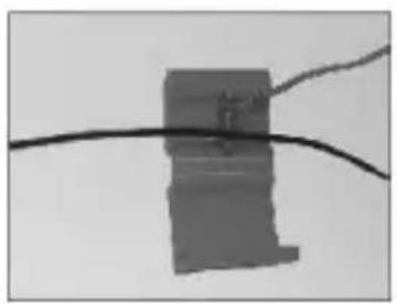
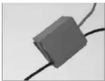
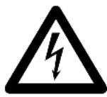
To ensure safe connections between the cables, it is advisable to use the provided cable connectors (see left).
Using the provided cable connectors:
A) Insert the cable to be tapped.
B) Insert the cable to be connected to it.
C) Lock the connector manually.
- Connect the red cable to the positive connection of the back-up light.
- Connect the black cable to an earthing point on the car body. Make sure that the earthing contact with the body is good (remove paint from the contact surface if necessary).
7.2 Connecting the monitor
The provided monitor allows you to connect a separate DVD player or similar (optional).
If you want to connect a DVD player to the monitor, connect the video and audio sockets of your DVD player with the video and audio connectors of the monitor.
The yellow RCA socket is used for the video signal, the red socket for the right audio signal and the white socket for the left audio signal.
The monitor must be in AV mode to play back the image of the DVD player.
Select the desired power source for the monitor.
Power connection via the provided 12/24 V/DC car adapter:
- Connect the 12/24 V/DC car adapter to the power connection of the monitor.
- Plug the 12/24 V/DC car adapter into the vehicle cigarette lighter socket. The red LED on the 12/24 V/DC plug lights up.
- Press the "POWER" button on the monitor or the "POWER" button on the remote control. The red LED on the "POWER" button on the monitor lights up.
Connecting the monitor to the vehicle's power source using a cable:
- Select the installation path for the connecting cable from the monitor's place of installation to the vehicle's fuse box.
- Look for the 12V+ clamp in the vehicle's fuse box. The clamp only provides power when the ignition key is in the ignition lock and turned into the first position.
- Connect the red wire of the connecting cable to this clamp.
- Connect the black wire of the connecting cable to earth.
Functional check
You can check if all cables have been properly connected by:
- reconnecting the battery.
- by inserting the ignition key into the ignition lock and turning it into the first position.
- connecting the monitor cable to the monitor.
- pressing the "POWER" button on the monitor or the "POWER" button on the remote control. The red LED on the "POWER" button on the monitor lights up.
If the camera signal is not received (also see information on channel selection), "NO SIGNAL" is displayed on the monitor.
8. Display and control elements
The camera features infrared LEDs for night vision. Please note that image rendition is black and white when the IR LEDs are active during darkness.
9. Operation
- Press the "Power" button (8) on the monitor or the "POWER" button (14) on the remote control to switch on the monitor. The red LED on the "POWER" button (8) lights up.
- Remove the protective battery foil from the battery compartment of the remote control as illustrated on the right (if you have not already done so).
10. Remote control button functions
This chapter explains the operating and setup options of your radio system using the buttons of the remote control. Functions available on the monitor as well are also explained in the following.
| Button Function | ||
| POWER Press this button to turn the monitor on or off. | ||
| TURN This button serves to rotate the displayed image by 90°.Press this button to make the desired setting. | ||
| MUTE You can mute the monitor with this button. | ||
| DISPLAY This button only has a function in AV mode (e.g. when a DVD player is connected).Press this button to switch between 4:3 and 16:9 display format. | ||
| Button | Function | |
| M -+ Down Up | MENU Press the “MENU” button (20) to select the desired UP/DOWN C HANNEL, BRIGHTNESS, COLOR, CONTRAST, MIRROR and VOLUME. Press the “MENU” button (20) repeatedly until the desired menu is displayed. Then set the desired value with buttons “+” and “-”. Making settings using the monitor buttons: Press the “MENU” button (10) on the monitor to access the menu for the above settings. Use buttons “UP” (9) and “DOWN” (11) to set the desired value. | |
| ① ② CH1 - CH4 Press | CH1 - CH4 Press | buttons “CH1” to “CH4” (17) to select the desired camera channel directly. |
| ③ ④ | SCAN If you press the “SCAN” button (22), the system switches through channels CH1 to CH4 at 5-second intervals. Please note that it is not possible to select the setup menu during the SCAN process by pressing the “MENU” button (20) on the remote control or the “MENU” button (10) on the monitor. You first have to abort the SCAN process by pressing the “SCAN” button (22) again. The SCAN process is active as long as the channel display flashes (green) in the top right-hand corner of the screen. The SCAN process is completed as soon as the channel display stops flashing or is no longer displayed. | |
| Button Function | ||
| RECEIVER | AV/ Press the “AV/RECEIVER” button (23) to switch between AV mode and RECEIVER mode. AV mode In AV mode, the images of the connected player are shown in the monitor display (5). RECEIVER mode In RECEIVER mode, the images of the used camera are shown in the monitor display (5). | |
11. Replacing the battery
If the range of the provided remote control is reduced, the battery (type: CR2025, 3 V/DC) has to be replaced.
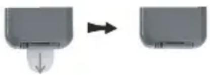
To properly replace the battery, proceed as follows:
- Pull out the battery holder from the remote control as illustrated to the right.
- Remove the used battery.
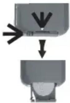
- Insert a type CR2025 (3 V/DC) battery into the battery holder. Observe the polarity (see the illustration on the back of the remote control).
- Carefully slide the battery holder back into the remote control.
12. Maintenance and cleaning
Regularly check the technical safety of the product, e.g. for damage to the connections or the sensors.
A clean, dry and soft cloth is sufficient to clean the outside of the camera and the monitor. For more resistant dirt on the camera, you can moisten the cloth with lukewarm water.
Clean the camera lens very carefully, you may otherwise scratch it. Do not apply too much pressure on the glass front of the camera or the monitor display as they might break.
13. Disposal
a) General
Please dispose of the unserviceable device according to the current statutory requirements.
b) Batteries and rechargeable batteries
The end user is legally obliged (battery regulation) to return used batteries and rechargeable batteries. Do not dispose of used batteries in the household rubbish.
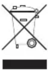
Batteries containing hazardous substances are labelled with the symbols shown to the left. These symbols indicate that disposal of these batteries in the household rubbish is prohibited. The heavy metals concerned are Cd = cadmium, Hg = mercury, Pb = lead.
You can return used batteries/rechargeable batteries/coin cell batteries free of charge at the official collection points of your community, in our stores, or wherever batteries/rechargeable batteries/coin cell batteries are sold!
You will thus carry out your legal obligations and contribute to the protection of our environment!
14. Specifications
a) Camera
Operating voltage: 12 V/DC or 24 V/DC
Sensor: CCD
Resolution: 500 × 582 pixels (PAL)
Horizontal angle: approx. 80^
Aerial: 50 Ohm SMA
Radio frequency: 2.4 2.483 GHz
IR range: approx. 5 m
Modulation: FM
Dimensions (W x D x H): approx. 95 x 52 x 61 mm
Weight: approx. 400g
b) Monitor
Operating voltage: 12 V/DC or 24 V/DC
Aerial: 50 Ohm SMA
Resolution: 480 × 234 pixels
Current consumption: max. approx. 900 mA
Dimensions (W x D x H): approx. 196 x 27 x 127 mm
Weight: approx. 450g (excluding monitor mount)
c) Remote control
Operating voltage: 3 V/DC coin cell (type: CR2025)
Dimensions: approx. 86 × 40 × 7 mm
Declaration of conformity
We, Conrad Electronic, Klaus-Conrad-Straße 1, 92240 Hirschau, hereby declare that this product adheres to the fundamental requirements and the other relevant regulations of Directive 1999/5/EC.

You can find the Declaration of Conformity for this product on the Internet at www.conrad.com.
F Table des matieres
Chere cliente, cher client,
5. Indications relatives aux piles
Copyright 2010 by Conrad Electronic SE.

Legal notice
These operating instructions are a publication by Conrad Electronic SE, Klaus-Conrad-Str. 1, D-92240 Hirschau (www.conrad.com).
All rights including translation reserved. Reproduction by any method, e.g. photocopy, microfilming, or the capture in electronic data processing systems require the prior written approval by the editor. Reprinting, also in part, is prohibited.
These operating instructions represent the technical status at the time of printing. Changes in technology and equipment reserved.
Copyright 2010 by Conrad Electronic SE.

Information legales
Copyright 2010 by Conrad Electronic SE.

Colofon
Copyright 2010 by Conrad Electronic SE.
V3_1110_01/HK