857907 - Rear Camera CONRAD - Free user manual and instructions
Find the device manual for free 857907 CONRAD in PDF.
Frequently Asked Questions - 857907 CONRAD
User questions about 857907 CONRAD
0 question about this device. Answer the ones you know or ask your own.
Ask a new question about this device
Download the instructions for your Rear Camera in PDF format for free! Find your manual 857907 - CONRAD and take your electronic device back in hand. On this page are published all the documents necessary for the use of your device. 857907 by CONRAD.
USER MANUAL 857907 CONRAD
These operating instructions belong with this product. They contain important information for putting it into service and operating it. This should be noted also when this duct is passed on to a third party.
Therefore look after these operating instructions for future reference!
Thank you for purchasing this reversing video system.
By purchasing this set, you have acquired a product designed to the current state of the art and operationally reliable.
This product complies with the requirements of the applicable European and national directives. Compliance was documented, the corresponding statements and documents are deposited with the manufacturer. To maintain this status and to ensure risk-free operation, the user must comply with these operating instructions!
For a fast response of your technical enquiries please contact or consult our Technical Advisory Service:
Germany: Tel. + 49 9604 / 40 88 80
Fax + 49 9604 / 40 88 48
E-mail: tkb@conrad.de
Mon to Thurs 8.00am to 4.30pm
Fri 8.00am to 2.00pm
Intended Use
The reversing video system is used to display obstacles when parking or reversing a car. It uses ultra sound sensors and a reversing camera with IR lighting. The reversing image and the distance to possible obstacles are displayed on the TFT colour screen integrated in the rear-view mirror. Obstacles are additionally acoustically indicated with a beep.
This product is only approved for connection to a 12V DC board mains with the car battery's minus p at the car body. It must only be installed and used in cars and trucks with this board voltage type.
The integrated screen (image diagonal approx. 8.5cm (3.5^ ) ) in the rear-view mirror is only permissible when reversing for parking. The clamp holders make it possible to attach the TFT rear-view mirror to 1 vehicle's own rear-view mirror easily.
The user must ensure performance of the installation in a manner that protects the control electronics, signal encoders and the connection box from moisture and wetness.
Any use other than that described above can damage the product and may involve additional risks such as short circuit, fire, electric shock, etc.
No part of this product must be modified or converted!

The safety information must be observed under all circumstances!
Table of Contents
Introduction 17
Intended Use 18
Product Description 19
Explanation of Symbols 19
Safety Information 20
Description of Individual Parts 22
Preparation 23
Installation 23
Connection 25
Commissioning 27
Cleaning 28
Disposal 29
Troubleshooting 29
Technical Data 30
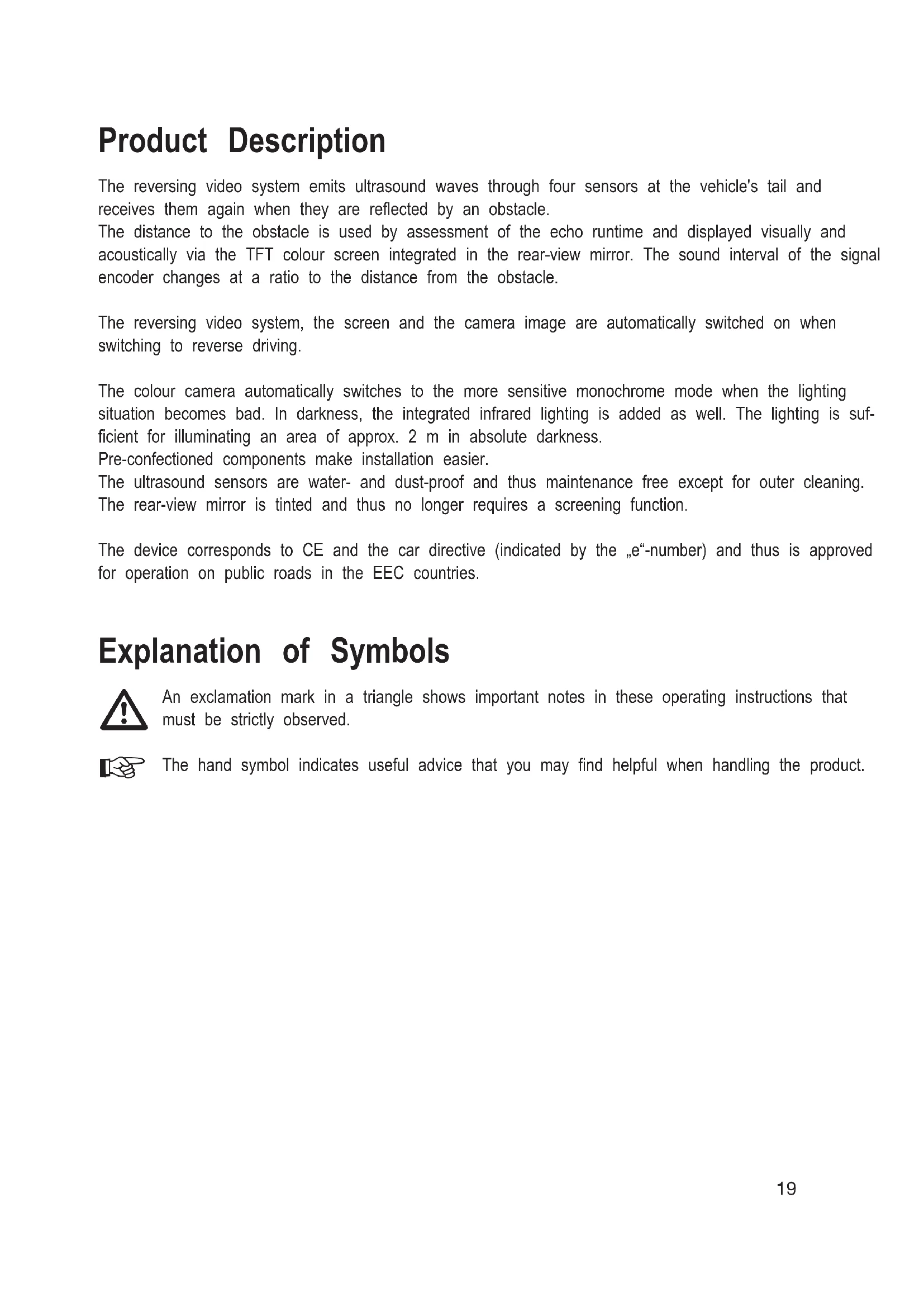
Product Description
The reversing video system emits ultrasound waves through four sensors at the vehicle's tail and receives them again when they are reflected by an obstacle.
The distance to the obstacle is used by assessment of the echo runtime and displayed visually and acoustically via the TFT colour screen integrated in the rear-view mirror. The sound interval of the signal encoder changes at a ratio to the distance from the obstacle.
The reversing video system, the screen and the camera image are automatically switched on when switching to reverse driving.
The colour camera automatically switches to the more sensitive monochrome mode when the lighting situation becomes bad. In darkness, the integrated infrared lighting is added as well. The lighting is sufficient for illuminating an area of approx. 2m in absolute darkness.
Pre-confectioned components make installation easier.
The ultrasound sensors are water- and dust-proof and thus maintenance free except for outer cleaning.
The rear-view mirror is tinted and thus no longer requires a screening function.
The device corresponds to CE and the car directive (indicated by the "e"-number) and thus is approved for operation on public roads in the EEC countries.
Explanation of Symbols

An exclamation mark in a triangle shows important notes in these operating instructions that must be strictly observed.

The hand symbol indicates useful advice that you may find helpful when handling the product.
Safety Information

Please read the entire operating instructions before using the product for the first time. They contain important information on how to operate the device correctly.
The guarantee/warranty will expire if damage is incurred resulting from non-compliance with the operating instructions! We do not assume any liability for consequential damage!
We do not assume any liability for property damage and personal injury caused by improper use or non-compliance with the safety instructions! In such cases, any warranty/guarantee will expire.
To ensure safe operation, the user must observe the safety information and warning notes in these operating instructions.
The unauthorized conversion and/or modification of the device is inadmissible because of safety and approval reasons.
The device is only intended as an aid when reversing. It does not relieve the driver from his obligation to take care. Some obstacles may not or not reliably be recognised due to the manner in which the dev works.
The device only works properly when reversing slowly. When driving faster, the warning may not be in time.
The device's function may be impaired by strong contamination on the sensors, exhaust development or rain.
The sensors and camera must not cover the rear lights, the license plate or any other devices of the or protrude over the vehicle contour.
During installation and operation, observe the applicable approval provisions and the road traffic ordinance (Straβenverkehrsordnung).
Before any installation, always disconnect the battery minus pole at the vehicle electrics. This prevents danger of short circuit. Only connect the negative pole of the battery when you have completely connected the system and checked the connections. In this respect, consider the information of the vehicle producer to avoid losing vehicle-specific data memory.
You should only use a voltmeter or a diode test lamp for checking the voltage on the on-board cables. normal test lamps consume excessive currents and can thus damage the electronic system of the car.
When laying the cables, make sure that they are not squeezed or scoured on sharp edges. Use rubber grommets for the feed-though points.
Any changes in the vehicle that become necessary for the installation of the CD tuner or other components must be carried out in such a way that neither traffic security nor the stability of the car are affected.
If there are any doubts regarding selection of the installation site, inquire for information from your car vendor.
Before drilling the attachment holes, make sure that no electric cables, brake lines, the fuel tank or similar are damaged.
When using tools to install your parking aid, observe the tool manufacturer's safety information.
When installing the components, take into consideration the risk of accident which can arise from devices being torn away in case of an accident. Therefore, you should secure every component in a place where it cannot be dangerous to passengers.
If proper operation of the device is no longer possible, power it down at once and secure it against reactivation.
Avoid strong mechanical strain on the device.
Do not leave packaging material lying around carelessly. It may become a dangerous toy for children.
Keep the device out of reach of children. It is not a toy.
If you are not sure about the correct connection or if there are any questions that are not covered by the operating instructions, do not hesitate to contact our technical support or another specialist.
If you have reason to believe that the device can no longer be operated safely, disconnect it immediately and make sure it is not unintentionally operated. It can be assumed that safe operation is no longer possible if:
- the device shows any visible damage,
- the device no longer works and
- the device was stored under unfavourable conditions for an extended period of time or
- after it was exposed to extraordinary stress caused by transport.
Description of Individual Parts
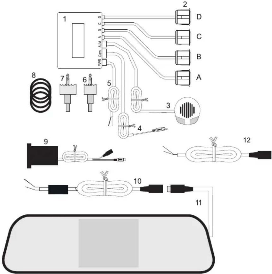
1 Control unit
2 Ultrasound sensors
3 Warning buzzer
4 Camera connection cables
5 PWR connection cable for voltage supply (reversing light)
6 Hole cutter 21 mm
7 Hole cutter 28 mm
8 Spacer rings for colour camera (already installed to camera (9))
9 CMOS colour camera
10 Screen connection cable
11 Rear-view mirror with integrated TFT screen
12 Connection cable for voltage supply to camera with reversing light
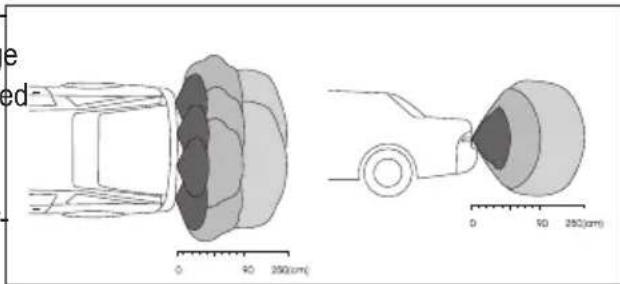
Preparation
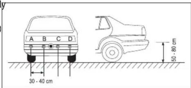
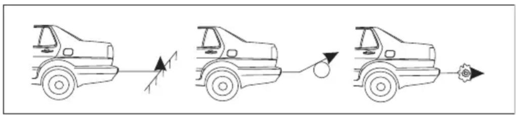
Use of four ultrasound sensors makes it possible to monitor almost the entire reversing range without any gaps. The sensors must be installed evenly spaced along the vehicle width.
The figure shows the sensor areas in two perspectives.
Installation
To be able to install the sensors, you need a drill to drill the required holes in the bumper. Carefully mark the hole positions before drilling.
Observe that the sensor angle is not impaired by vehicle parts. This would cause malfunction.
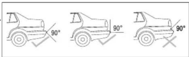
The ultrasound sensors must be installed eventl spaced along the vehicle width. The distance between the sensors must not exceed 30 - 40 cm.
The assembly height should be in the range between 50 - 80 cm.
Install the camera centrally in the middle to enable the best view angle.
Drill attachment holes

When drilling, observe the safety information of the drill. Observe that no lines and cables are damaged that are located in the drilling area.
Drill the holes for the four ultrasound sensors with the included 21mm drill and the opening for the camera with the 28 mm drill.

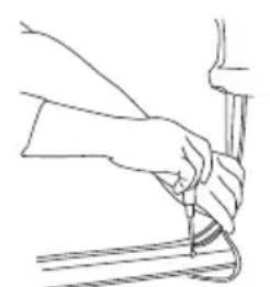
Deburr the holes after drilling with a file or a sharp blade.
Inserting ultrasound sensors and camera
The ultrasound sensors always have to be installed horizontally. Otherwise, wrong measurements may result. Push the sensors into the openings in the correct order until they are flush with the bumper. Loosen the knurled screw at the camera and adjust the camera to the bumper

with the metal spacer rings (8) if required. Do not screw the camera tight yet, since its viewing angle has to be adjusted.

Ensure that the ultrasound sensors are connected in the correct order. Start with sensor A at the rear left (also see figure in chapter "Installation"). If the order is changed, the direction alignment in the display (11) is not correct.
Placing lines and components
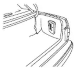
Guide the connection lines of the ultrasound sensors through the bumper to the trunk opening from the outside. Carefully place the lines inwards so that no moisture can enter the car.
Attach the control unit (1) with the included adhesive pad. A suitable position is the side wall in the water-protected trunk close to a reversing light. Observe that the connection lines of the sensors can reach the control unit (1).
Place the connection lines of the sensors according to the connection sketch in chapter „Connection".
Attach the warning buzzer (3) with the included adhesive pad as well. For this, remove the protective paper from the adhesive pad. Find the ideal position for attachment of the warning buzzer. The buzzer volume may be different depending on installation. A suitable position is, e.g., installation on the rear deposit or trunk cover.

The adhesive point must be perfectly free of dust and grease. Do not use the glue below 5^ , because this would not lead to reliable bonding. WI placing the lines in door pillars, etc., ensure that you do not impair or damage any safety-relevant devices (e.g. side airbags).
Rear-view mirror installation
The heart piece of the reversing video system is the rear-view mirror with integrated TFT screen. Pull apart the rear clamp of the rear-view mirror and place it on the vehicle's rear-view mirror. Place the connection lines in the vehicle roof fold.

When choosing the installation site, ensure that the display is not in the direct view area of the driver or in any safety-relevant areas (airbags, etc.).
Connection
After installation and placement of all components, the plug connections for the display and voltage supply must be made.
The following sketch shows how all components are wired.
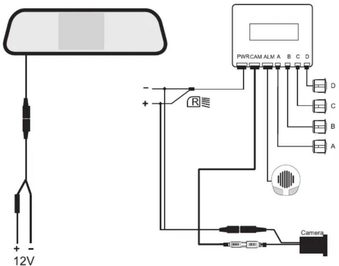
Create all plug connections as displayed in the connection sketch.
-
Connect the black plug of the monitor cable at the mirror (11) to the black plug of the connection cable for permanent power supply (10).
-
Plug the small white plug of the camera connection line (4), marked with "NTSC", into the socket "Camera/CAM" at the control unit (1). The plug only fits the socket in the correct polarity. At the end of the camera connection line, there is a signal line (yellow cinch plug).
- Connect the yellow cinch plug "NTSC" to the yellow cinch socket at the camera (9).
- Connect the black plug of the camera (9) to the connection cable for voltage supply (12)
- Connect the four plugs of the ultrasound sensors (A to D) in the correct order with the sockets „A,B and D" of the control unit (1).
Observe the correct order of the letters at the lines and plug sockets.
- Plug the cable of the warning buzzer (3) into the socket "ALM" of the control unit (1).
Once all plug connections have been made, the voltage supply for the mirror monitor and connection to the reversing lamp must be made.
The radio parking system consists of two parts that have to be connected to different power sources.
The monitor is connected to the ignition plus.
The ultrasound system, in contrast, must only work if the reverse gear is engaged. It is therefore fed the reversing light.
Find out the correct lines by voltmeter measurement or a diode test lamp.

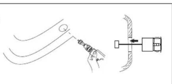
Use an optional cable cutting connector to very easily create a secure contact without separating the line. For this, place the cable cutting connector around the supply line and the conductor to be connected into the connector. Press the contact bridge onto the lines with pliers.
Always ensure permanent insulation at the contact point (e.g. insulated crushing connector, insulation tape, etc.)
Monitor connection
- Connect the red plus line (+) of the monitor connection cable (10) to the ignition plus. This circuit is secured via a fuse in the fuse box. Additional fuses are not required.
- Connect the black minus line (-) of the monitor connection cable (10) to a ground contact (e.g. car body).
Switching plus connection (reversing light)
Determine the correct line for the reversing lamp with the reverse gear engaged and the ignition on. The light and direction indicators should be off. Once you have found the right line, switch off the ignition again.
- Connect the red plus line of the PWR connection cable (5) to the plus contact of the reversing light.
- The black minus line of the PWR connection cable (5) must be connected to earth (car body).
- Connect the small white plug of the PWR connection cable (5) to the socket „PWR“ at the control unit (1).
- Connect the red plus line of the camera connection cable (12) to the plus contact of the reversing light.
- The black minus line of the connection cable (12) must be connected to earth (car body).
Final inspection and adjusting the camera
Check the wiring again. Take your vehicle electronics in operation again. The monitor switches on at initial commissioning. The camera signal is sent by radio to the monitor (11) by the control unit (1).
Engage the reverse gear with the ignition switched on. The reversing system switches on automatically after a brief time and is ready for use. The monitor shows the camera image. If an obstacle is recognised already, distance and direction are displayed as well.
Turn the camera at the tail of the vehicle into the correct horizontal position. Screw the camera tight with the attachment rings. For slanted surfaces, the metal spacer rings at the camera can be moved against each other to balance out unevenness.
Tighten the knurled screw at the camera.
Commissioning
The reversing video system consists of two connected systems. The reversing mirror with integrated monitor and the ultrasound reversing system.
With the reverse gear engaged, the ultrasound reversing system and the camera are activated. The camera sends the images to the colour monitor integrated in the rear-view mirror.
If an obstacle is recognised, distance and direction are displayed on the monitor as well.

Test the system before first use to get familiar with the displays and signals.
Only switch on the ignition (board voltage supply) and then engage the reverse gear. The monitor shows not only the sensor data but also the rear image.
Ask a second person to simulate the "obstacle" behind your car.
The obstacle person very slowly walks towards the rear of the car from a distance of approx. 2 metres. The shortest distance between the two vehicle sides and the obstacle is displayed on the screen at the top in metres. The bar display signals the direction and distance between the 4 sensors and an obstacle. The more bars are displayed, the closer is the obstacle.
Obstacle left Obstacle centre Obstacle right
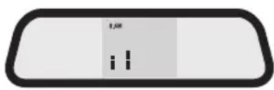
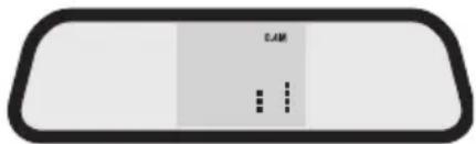
This distance to an obstacle is also displayed acoustically with increasing intensity of the signal tone (large distance = slow beep; small distance = fast beep).
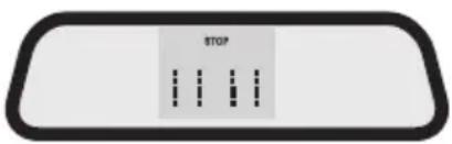
The following warning areas must be observed.
Safe area between 2.0 - 1.6 m (no sound, distance display).
Safe area between 1.5 - 0.9 m (slow warning sound, distance display).
Warning area between 0.8 - 0.5 m (faster warning sound, distance display).
Danger area between 0.4m - 0m (fast warning sound, monitor display "STOP" < 0.4 m).
In certain situations, the ultrasound measuring principle is not working reliably. This is possible where ultrasound waves are absorbed, e.g. at slight slopes, rounded and soft obstacles and in rain.
Cleaning
Clean the outer sensors regularly to prevent malfunction. Use a soft, clean and slightly moistened cloth for it.
Also clean the camera lens with a soft, clean, slightly moistened cloth.
Best clean the rear-view mirror with monitor with a soft, clean, slightly moistened and lint-free cloth without any scouring and chemical cleaning agents. Never push the display. It may be damaged.
Disposal
Old electronic devices are raw materials and should not be disposed of in the household waste. At the end of its service life, dispose of the device at the community collection points according to the applicable statutory regulations. It is prohibited to dispose of the device in the household waste. You thus fulfil the legal requirements and make your contribution to protecting the environment!
Troubleshooting
In purchasing the reversing video system, you have acquired a product designed to the current state of the art and operationally reliable.
Nevertheless, problems or errors may occur.
For this reason, the following is a description of how you can easily remove possible malfunctions yourself:

Always observe the safety information!
| Error Possible cause Solution | ||
| The reverse driving system does not switch on. | The reverse gear is not engaged | Engage the reverse gear. |
| No ignition voltage. Switch on | the ignition. | |
| The cables are defective. Check the plug connections (see connection figure), the fuse in the "fuse box" at the connection cable (10) or the flat fuse of the car voltage supply. | ||
| The display shows wrong distances, and there is a it signal sound although there is sufficient space. | programme error Take out the reverse gear and put in again (reset). | |
| The sensors are very dirty. | Clean the sensors regularly. | |

Repairs other than those described above may only be carried out by an authorised specialist. Individual defective image points (light or dark pixels) are due to the component and are not subject to the warranty. This does not reduce or impair system function.
Fuse Replacement
The monitor connection cable (10) is protected against overload with a separate fine-wire fuse.
A fuse replacement is required if the motor cannot be switched on anymore.
Proceed as follows for fuse replacement:
Carefully take apart the fuse box. Replace the defective fuse with a new fine-wire fuse of the same type and rated current.
Fine-wire fuse 5 × 20 ~mm , 3 ~A , 250 ~V . Screw on the fuse box again after inserting the new fuse.
Technical Data
DC operating voltage. 12V/DC car board mains with minus pole at earth
Power intake control unit........................ approx. 180 mA
Power intake camera...........................approx. 50 mA
Power intake monitor.. approx. 225 mA
Camera recording range . 80^ / 70^ (horizontal / vertical)
Radio transmission area approx. 8 m
Radio transmission frequency. 2.4 GHz
Monitor size. 8.5 cm (3.5")
Sensor recording range.. approx. 30 - 200 cm
Sensor cable length. 2.5 m
Monitor cable length 3.5 m
Camera cable length 1.7 m
Buzzer cable length. 2.4 m
Camera lighting 9 IR-LED
Fuse .Fine-wire fuse F3AL/250V (5 x 20 mm)
Operating temperature -20° to +70°C
Dimensions control unit (W x H x D) 99 x 72 x 26 mm
Dimensions rear-view mirror (W x H x D) 287 x 75 x 50 mm
Weight control unit. 85g
Mirror weight 270g
F Introduction
Chere cliente, cher client,
© Copyright 2011 by Conrad Electronic SE.
GB Legal notice
These operating instructions are a publication by Conrad Electronic SE, Klaus-Conrad-Str. 1, D-92240 Hirschau (www.conrad.com).
All rights including translation reserved. Reproduction by any method, e.g. photocopy, microfilming, or the capture in electronic data processing systems require the prior written approval by the editor. Reprinting, also in part, is prohibited.
These operating instructions represent the technical status at the time of printing. Changes in technology and equipment reserved.
© Copyright 2011 by Conrad Electronic SE.
F Information legales
© Copyright 2011 by Conrad Electronic SE.
NL Colofon
© Copyright 2011 by Conrad Electronic SE.
V3_0911_01/AB