
Comfort 210 - Garage door MARANTEC - Free user manual and instructions
Find the device manual for free Comfort 210 MARANTEC in PDF.
| Product type | Electric operator for garage door |
| Model | Marantec Comfort 210 |
| Power supply | 230 V ~ 50 Hz |
| Power | 250 W (running with lighting) |
| Pulling and pushing force | 500 N |
| Door movement speed | 0.12 m/s |
| Running time (full travel) | 88 seconds |
| Lighting | 1 bulb E14 max. 40 W, automatic shutoff after 180 s |
| Control circuit voltage | 24 V DC (low voltage) |
| Force stop type | Electronic via microprocessor, adjustable |
| Protection | For rooms protected from moisture |
| Compatible rail types | Chain or toothed belt rail |
| Available rail lengths | 2960 mm, 3180 mm, 4090 mm |
| Main functions | Remote control, push button, photocells (option), manual emergency release |
| Settings | Limit switches (open/close) by movable stops, programmable force stop |
| Number of possible remote controls | Several programmable transmitters |
| Transmitter battery | 12 V type A23 |
| Maintenance | No special maintenance, but regularly check force stop and mechanical condition of the door |
| Safety | Adjustable force stop, optional photocells, manual release |
| Door compatibility | Up-and-over door, sectional door, non-counterweighted up-and-over (with specific adapter) |
Frequently Asked Questions - Comfort 210 MARANTEC
User questions about Comfort 210 MARANTEC
0 question about this device. Answer the ones you know or ask your own.
Ask a new question about this device
Download the instructions for your Garage door in PDF format for free! Find your manual Comfort 210 - MARANTEC and take your electronic device back in hand. On this page are published all the documents necessary for the use of your device. Comfort 210 by MARANTEC.
USER MANUAL Comfort 210 MARANTEC
GB Installation and Operating Instructions
Garage Door Operator
Keep these instructions for later reference.
Installation and Operating Instructions ① ⑬
Electric Control Unit 14- 17
Cable Connecting Plan 18- 19
Test Instructions 20
Initial Operation and Maintenance Instructions 21
Technical Data 22
Page 16-27
Page 16-20
Page 20-25
Page 25
Page 26
Page 27
Page 27
Français
Gabel - Ringschlüssel SW 10
Gabel - Ringschlüssel SW 13
Steckschlüssel SW 10
Steckschlüssel SW 13
Please follow exactly the installation and fitting instructions in order to avoid mistakes in installation and damages to door and door operator.
Please keep these instructions for later reference. They contain important information regarding operational checks and maintenance work.

Preparation
Unpack the boom and the motor unit and keep it ready for mounting.

Following tools are required:
Combination wrench SW 10
Combination wrench SW 13
Socket wrench SW 10
Socket wrench SW 13
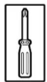
Screw driver, size 8
Screw driver, size 5
Phillips Screw driver, size 2
Phillips Screw driver, size 3
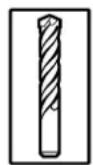
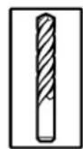
Masonry drill 10mm
Masonry drill 6mm
Metal drill, 05mm
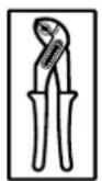
Pliers
Hack saw
Electric drill
Folding rule


Attention:
Before drilling, cover the motor unit with foil or cardboard.
Drilling dust and chippings can lead to malfunctions.

Pre-adjustment of travel cut-out
- Fit two stops (B) in front of sprocked wheel holder resp. chain wheel holder (A).
- For pre-adjustment of the travel cut-out install two controllers (acc. to drawing 3) to the transmission resp. chain.
- The sides of controllers, which are chamfered, have to show to the centre of the boom.

Attention:
Pre-adjustment depends on the length of boom.
Please stick to the measures below:
boom length L: 2960 mm 3180 mm 4090 mm
distance X: 700 mm 900 mm 1700 mm
A Sprocket wheel holder / chain wheel holder
B Detent piece disconnection
C Plastic screw, diam. 4x6 - round head
D Upper side of controller
E Downward side of controller
F Plastic screw, diam. 3,5x12 - countersunk head
G Transmission connectore / chain connector

Attention:
The supply package for Comfort 210 contains controllers for transmission and chain. The controllers which have to be used for this can be recognized by their inner profile (form of transmission / form of chain).
For chain booms remove the prefitted controller and include it in installation.

Connection of boom to motor unit:
- Push the adapter sleeve (A) onto the fine-toothed gear shaft to the detent.
- Fit the boom onto the adapter sleeve in the correct direction, align laterally and lower it onto the motor unit using light pressure.

Attention:
Do not use force. If the boom is aligned parallel to the upper side of the motor unit, a short pull on the carriage is sufficient to lower the boom to the motor unit without force.
Screw the boom onto the motor unit using two clamping brackets (C) and four Phillips screws (D) (see picture 4).

Fitting suspending cramp onto boom
Function and position of the suspending cramp (see point 10).

Installation of lintel joining plate
Screw the lintel joining plate (A) onto the boom end (B).
The lintel joining plate has to remain turnable.

Garage door operator for up-and-over doors:
- Screw the lintel joining plate (A) together with boom to the top door frame, lintel or ceiling, so that the upper door edge lies approx. 10mm below the horizontal downward boomed edge - measured from the highest point of the opening course (see pictures 7 and 11).
- Put the motor unit on a trestle or another suitable object until it is fixed later on to the ceiling.
- Join two door link brackets (B) to the door connector (C) according to drawing 7 and screw them with 4 screws to the centre of the upper door edge. Drill bit 5mm .
- Insert door link (D) with bolt (F) into the carriage (E) and fix it with 2 screws.
- Connect door link to door connector.
Remove the door locks or put them out of operation.

Garage door operator for sectional doors:
- Screw the lintel joining plate (A) with boom to the lintel or ceiling, so that the upper lamella of the door lies approx. 10mm below the horizontal downward boom edge - measured from the highest point of the opening course (see pictures 8.1 and 11).
- Put the motor unit on a trestle or another suitable object until it is fixed later on to the ceiling.
-
Join two door link brackets (B) to the door connector (C) and screw them with 4 screws to the upper door lamella (see picture 8.1). Drill bit 5mm.
-
If necessary, the motor unit can be installed 200mm off-centre.
-
For wooden sectional doors please use wood-screws 5 × 35 mm . Drill bit : 3 mm .
-
Screw two self-tapping screws (D) into the door connector until the points of the screws are situated in front of the lamella.
- Insert door link (E) with bolt (G) into the carriage (F) and fix it with 2 screws.
- Connect door link to door link bracket (see picture 8.1).
Remove the door locks or put them out of operation.

Attention:
For big and heavy sectional doors please use additionally door connector attachment Spezial 111, Art.-No. 47 574 (see picture 8.2).
(This is not part of the supply package)

Garage door operator for retractable up-and-over door:
Adapter arm Special 102, Art.-No. 564 865 and photocell Special 606, Art.-No. 47 816 are required. (These are not part of the supply package Comfort 210).
Before installing the motor unit, put the door locks out of operation or remove them.
- Screw the lintel joining plate (A) with boom to the top door frame, lintel or ceiling, so that the upper door edge lies approx. 10mm below the horizontal downward boom edge - measured from the highest point of the opening course (see pictures 9 and 11).
- Put the motor unit on a trestle or another suitable object until it is fixed later on to the ceiling.
Fitting the adapter arm:
- Screw the support bracket (B) to the upper door edge using 6 self-tapping screws (Drill bit :5mm ).
- Centre of support bracket equals to the centre of boom.
- Put adapter arm (C) into support bracket (B) and screw it to the door cross strut (E) using two angle plates (D).
(Drill bit : 5mm ) in the door cross strut (4 x)
(Drill bit : 7 mm) in the adapter arm (2 x)
- Screw the angle plates to the adapter arm using two screws M6 x 10 and hexagon nuts.
- Insert linking bar (G) with bolts (J) into the carriage (F) and fix with 2 screws. - Open door fully,
- Connect linking bar with adapter arm (C).
- Observe the indicated measurements.
While lowering the boom and by extending the linking bar the door opening is enlarged. The linking bar may only be extended so far that the inner pressure rolls (H) do not touch the limiting screws (I).

Suspension of motor unit:
Fix 1 support plate (A) in front of motor unit (see pictures 10 and 11).
- Bend it according to the site requirements.
Suspension of boom:
- Push 1 support plate (A) through suspension cramp (B) and bend projecting parts (see picture 10).
- For positioning of boom suspension see picture 11.

Site requirements
- Suspend the motor unit with boom in such a way that the upper door edge lies approx. 10 mm below the horizontal downward border of boom - measured from the highest point of the opening course (see points 7, 8, and 9).
- Attachment to the ceiling is made according to site requirements.
(Pleases mind the indications of measurements for dowel drilling).

Installation of bulb
- Turn in bulb E 14, (max. 40 W)
- Clip in cover of lamp and
- fix with securing screw.
After receiving an impulse, the bulb is glowing for approx. 3 min.

Attention:
Before changing bulb it is necessary to disconnect power supply line.
Bulbs are not covered by warranty.

Quick release:
- To separate door and motor unit, pull cord (A) downward to the stop.
- The separation can be noticed, when the front edge of the red slide bar (B) is situated in the carriage above the back arrow (symbol 'lock open') (see picture 13).

Attention:
When disengaged, the door may only be moved in a moderate speed!
In order to prevent the carriage from colliding with the motor housing on manual opening of the door, the travel path of the door in the opening direction must always be limited.
To restore power operation of the door, pull the cord again downwards and start the motor.

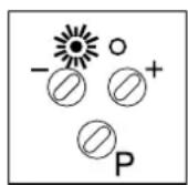
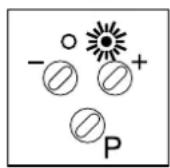
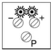
Electronic control unit:
A green LED
B red LED
C
D
E IMPULSE test button;
F Connecting terminals for IMPULSE button and photocell
G Connecting terminal for STOP button
T Transmitter photocell
R Receiver photocell
S3 IMPULSE button
S4 STOP button (to connect, remove bridge)
Symbols Explanation

LED not glowing
O
LED glowing

LED flashing

LED flashing rapidly

green and red LED's flashing in alteration

green and red LED's flashing rapidly in alteration.
operating states Explanation
green LED (A) glowing door open
red LED (B) glowing door closed
green LED (A) and door located between end-of-travel positions red LED (B) glowing
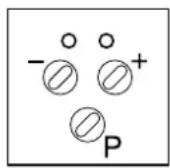
no LED glowing door in motion
Fault messages Explanation
green LED (A) flashing automatic cut-out 'open' activated rapidly
red LED (B) flashing automatic cut-out 'close' activated rapidly
green LED (A) and photocell not connected or defective red LED (B) flashing rapidly

green LED (A) and control electronics defective red LED (B) flashing rapidly in alteration

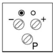
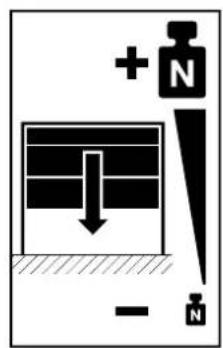
1. Setting the 'OPEN' travel limit
The control unit is in the operating state as soon as the main plugs have been connected.
- Green and red LED's are glowing.
- After pressing button P for the first time, the door travels to its pre-set travel limit 'DOOR OPEN' (see point 3).
- The green LED is glowing.
- If the door shall travel further in the OPEN direction, the contact on the chain or on the transmission has to be shifted in the direction of arrow (A_+) (see picture 15.1).
- If the door shall not travel this far in the OPEN direction, shift the contact in the direction of arrow (B-).

Attention:
It is important to disconnect power supply line before making any adjustments to the contacts.
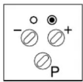
2. Setting the 'CLOSE' travel limit
After reaching the OPEN end-of-travel position and after pressing once again button , the door travels to its pre-set CLOSE travel limit (see point 3).
The red LED is glowing.
- If the door shall travel further in the CLOSE direction, the contact on the chain or on the transmission has to be shifted in the direction of arrow (A + ) (see picture 15.2).
- If the door shall not travel this far in the CLOSE direction, shift the contact in the direction of arrow (B-).
A top of contact
B bottom of contact
C plastic screw 3,5× 12 - countersunk head

Hand transmitter
A battery - flashing control light
B operating buttons
C cover of battery
D battery 12 V A23
E contacts for programming
- To change and insert battery open cover
- When changing battery, make sure of right poling.
F Holder for hand transmitter (for fixing to wall or to sun protector)
G Sun protector clip

Attention:
Only use hand transmitter, when you are sure that there are neither persons nor objects within the door's range of travel.
Keep hand transmitters out of reach of children!
Batteries are excluded from warranty.

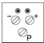
1. Programming the 'OPEN' automatic cut-out
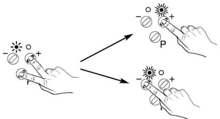

Setting of forces which travel the door to the OPEN direction, before the limitation of forces is performed by the control unit.
- Press simultaneously (approx. 3 sec.) buttons
and to activate the 'OPEN automatic
cut-out'programming mode.
-
The green LED starts to flash.
-
Select the required value pressing buttons (
and
The LED's indicate the following three settings of forces:
green LED is glowing: min. forces = stage 1
green and red LED's are glowing: intermediate forces = stages 2 - 15
red LED glows: max. forces = stage 16
- Save by pressing programming button P.
Set the automatic cut-out as sensitively as possible (max. 150 N at the closing edge).
2. Programming the 'CLOSE' automatic cut-out
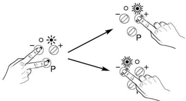
Setting of forces which travel the door to the OPEN direction, before the limitation of forces is performed by the control unit.
- Press simultaneously (approx. 3 sec.) buttons cut-out' programming mode.
and to activate the 'CLOSE automatic
The red LED starts to flash.
Select the required value by pressing buttons and .
The LED's indicate the following three settings of forces:
green LED is glowing: minimum force = stage 1
green and red LED's are glowing: intermediate force = stages 2 - 15
red LED is glowing: maximum force = stage 16
- Save by pressing programming button

Set the automatic cut-out as sensitively as possible (max. 150 N at the closing edge).
3. Programming the remote control / photocell
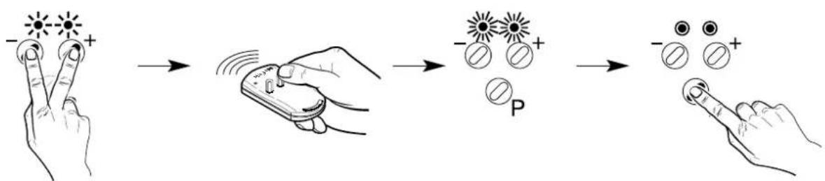
Press simultaneously (approx. 3 sec.) the buttons and to activate the 'remote control'
- Green and red LED's start to flash and after releasing the buttons, the LED's are glowing permanently.
- Press the corresponding button of the hand transmitter until green and red LED flash rapidly.
- Press now programming button P to save coding.
- The green and red LED's flash in alteration.

- Pressing button makes it possible to connect external photocell.
-
The green LED glows. (The photocell is not part of the supply package).
-
Pressing button makes it possible to operate motor unit without external photocell.
- The red LED glows.
- Save by pressing programming button .

Cable connecting plan
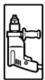
A Comfort 210 motor unit
B Safety electric socket 230V 50Hz
C Control unit board Comfort 210
D Interior button with connection cable (not included in the supply package)
E Key switch (not included in the supply package)

Comfort 210 wiring diagram
M Motor unit
T1 Transformer
S1 OPEN limit switch
S2 CLOSE limit switch
T Transmitter photocell
R Receiver photocell
S3 IMPULSE button
S4 STOP button
bn brown
gn green

Attention:
Low voltage!
External voltage at the plug terminals will completely destroy the whole electronics.

Attention:
Observe the local safety regulations!
Always lay mains supply cables and control cables separately.
| Fault characteristic Remedy | |
| The motor cannot be operated | ·Check the mains connection Connect a lamp to the mains electric socket used for the motor. If the lamp lights up, the mains supply is OK. If not, check the fuses. |
| The motor starts, but the door is not opened | ·Ensure that the carriage engaged (point 13) |
| The motor can only be operated pressing button P but not by the remote control | ·Check the battery in the hand transmitter. ·Relearn the coding (point 17/3) |
| Insufficient range of remote control (less than 6 m) | ·Put the remote control to another place in the car. Point with remote control to the door. Replace battery. |
| The door travels downwards, but it stops before it is fully closed | ·Ensure, that the door is in perfect condition as well as greased and balanced carefully. ·Check the setting of CLOSE travel limit (point 15/2) ·Check the CLOSE automatic cut-out (point 17/2) |
| The door travels upwards, but it stops before it is fully opened | ·Ensure, that the door is in perfect condition as well as greased and balanced carefully. ·Check the setting of OPEN travel limit (point 15/1) ·Check the OPEN automatic cut-out (point 17/1) |
| The door can only be opened | ·Check the setting of CLOSE travel limit (point 15/2) ·Check the CLOSE automatic cut-out (point 17/2) ·Check connection (point 14) or programming of photocell (point 17/3) |
| Noisy operation | ·Ensure that all fixings are carefully tightened. Also ensure that the door is in perfect condition as well as greased and balanced carefully. |
| The motor cannot be operated using the wall button | ·Check the connections on the connecting terminal of motor (point 14). ·Check the connections to the wall button. |
| The door moves itself for unknown reasons. | ·Disconnect all impulse transmitters (wall button, key switch etc.) from terminal block. Reconnect one impulse transmitter after the other and check it every time by a test run. The door should then start to move. In case the motor operates in one case by itself, check the cabling searching for a faulty contact. If you cannot clearly determin the reason, disconnect the respective impulse transmitter (point 14) |

Start-up:
Power-operated windows, doors and gates for industrial use have to be checked by a specialist after installation, before first operation and when necessary. Minimum check interval once a year.
Maintenance instructions
The Comfort 210 Garage Door Operator works largely maintenance-free.
Please observe following points in order to guarantee a function without troubles:
- Check regularly the settings of 'OPEN and CLOSE' automatic cut-out.
- Check regularly all movable parts of door and motor system and keep them easily movable.
- Manual operation should run easily, check as well regularly the separate counterbalance of the door

Technical data:
Garage Door Operator
Comfort 210
Connected loads:
230 V
250 W (operating with lighting)
Door travel speed:
0,12 m/s
Push and pull force:
500N
Excess travel stop:
88 Sek.
Lighting:
1x40W E 14,
automatic switch-off after approx. 180 sec.
Control voltage:
low voltage 24 V DC
Automatic cut-out:
electronic power limit by microprocessor and current sensor.
Protection category:
only for dry buildings
No part of this manual may be reproduced without our prior written approval.
We reserve the right to make technical changes in the interests of progress.
F Copyright


- GB Installation and Operating Instructions
- Page 16-27
- Français
- Preparation
- Following tools are required:
- Attention:
- Pre-adjustment of travel cut-out
- Connection of boom to motor unit:
- Fitting suspending cramp onto boom
- Installation of lintel joining plate
- Garage door operator for up-and-over doors:
- Garage door operator for sectional doors:
- Remove the door locks or put them out of operation.
- Garage door operator for retractable up-and-over door:
- Before installing the motor unit, put the door locks out of operation or remove them.
- Fitting the adapter arm:
- Suspension of motor unit:
- Suspension of boom:
- Site requirements
- Installation of bulb
- Quick release:
- Electronic control unit:
- Symbols Explanation
- operating states Explanation
- Fault messages Explanation
- Setting the 'OPEN' travel limit
- Setting the 'CLOSE' travel limit
- Hand transmitter
- Programming the 'OPEN' automatic cut-out
- Programming the 'CLOSE' automatic cut-out
- Programming the remote control / photocell
- Cable connecting plan
- Comfort 210 wiring diagram
- Start-up:
- Maintenance instructions
- Technical data:
- Garage Door Operator
- Comfort 210
- Connected loads:
- Door travel speed:
- Push and pull force:
- Excess travel stop:
- Lighting:
- Control voltage:
- Automatic cut-out:
- Protection category:
Brand : MARANTEC
Model : Comfort 210
Category : Garage door