
SBN10 - Flash NIKON - Free user manual and instructions
Find the device manual for free SBN10 NIKON in PDF.

| Product type | Underwater flash with TTL control mode |
| Brand and model | Nikon SB-N10 |
| Dimensions (L × H × D) | Approx. 87 × 133 × 140 mm (excluding protrusions) |
| Weight (without batteries) | Approx. 627 g |
| Weight underwater (with batteries) | Approx. 90 g |
| Power supply | Four AA alkaline batteries or AA NiMH rechargeable batteries |
| Guide number (air, 100 ISO, without diffuser) | 28 at full power |
| Guide number (air, 100 ISO, with wide-angle diffuser) | 20 |
| Illumination angle (without diffuser) | 80° horizontal and vertical |
| Illumination angle (with wide-angle diffuser) | 110° horizontal and vertical |
| Effective range | 0.3 m to 4 m (depending on ISO sensitivity and aperture) |
| Flash modes | TTL, Manual M1/M2 |
| Modeling lamp | Yes (on/off via command) |
| Maximum operating depth | 100 m |
| Operating temperature (in water) | 0 °C to 40 °C |
| Recycle time (alkaline batteries) | Approx. 2.5 s |
| Recycle time (NiMH rechargeable batteries) | Approx. 1.8 s |
| Battery life (alkaline batteries) | Approx. 180 flashes |
| Battery life (NiMH rechargeable batteries) | Approx. 220 flashes |
| Materials | Polycarbonate resin and ABS resin |
| O-ring | WP-O3000 (replaceable) |
| Auto power off | Yes (after 30 minutes of inactivity) |
| Included accessories | Wide-angle diffuser SW-N10A, cord, manual, warranty, silicone grease WP-G1000 |
| Required accessories (sold separately) | Underwater bracket SK-N10A, fiber optic cable SC-N10A, adapter SR-N10A |
Frequently Asked Questions - SBN10 NIKON
User questions about SBN10 NIKON
0 question about this device. Answer the ones you know or ask your own.
Ask a new question about this device
Download the instructions for your Flash in PDF format for free! Find your manual SBN10 - NIKON and take your electronic device back in hand. On this page are published all the documents necessary for the use of your device. SBN10 by NIKON.
USER MANUAL SBN10 NIKON
https://reg.nikon-image.com/
カスタマーサポート
natural_image
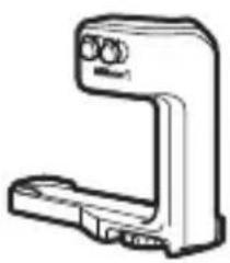
Line drawing of a cylindrical device with a central screen and mounting bracket (no text or symbols)SB-N10 本体
natural_image
Simple line drawing of a circular mechanical component with no text or symbols□ 水中ワイドパネル SW-N10A

natural_image
Simple line drawing of a tube with a textured cap (no text or symbols)□ シリコングリス WP-G1000
natural_image
Technical line drawing of a mechanical bracket or support structure (no text or symbols)□ 水中ブラケット SK-N10A

natural_image
Simple line drawing of a mechanical clamp or bracket (no text or symbols)natural_image
Line drawing of a handheld device with a flat top and side connectors (no text or symbols)natural_image
Line drawing of a mechanical component with gear and control knob (no text or symbols)natural_image
Technical line drawing of a mechanical device with a rotating shaft and housing (no text or symbols)natural_image
Diagram of a camera assembly with a base mount and adjustment arrow (no text or symbols)natural_image
Diagram of a digital camera module with a base case and control panel (no text or symbols)natural_image
Line drawing of a DSLR camera with attached lever mechanism (no text or symbols)natural_image
Technical line drawing of a camera with directional arrows indicating motion or force (no text or symbols)Jp
natural_image
Technical line drawing of a mechanical assembly with no visible text or symbolsnatural_image
Mechanical assembly diagram showing a wrench inserted into a component with an arrow indicating the process (no text or symbols present)natural_image
Mechanical assembly diagram showing a valve and connector (no text or symbols)
natural_image
Line drawing of a DSLR camera with attached optical lens (no text or symbols)Nikon 1 AW1 をお使いの場合
natural_image
Line drawing of a DSLR camera with lens and handle (no text or symbols)natural_image
Line drawing of a digital camera with an attached base and a screen, showing no text or symbols.natural_image
Diagram of a camera assembly with a mounted lens and base mount (no text or symbols)natural_image
Diagram of a digital camera module with two buttons and a screen, showing no text or symbolsnatural_image
Technical line drawing of a camera module with no visible text or symbolsnatural_image
Technical line drawing of a camera with directional arrows indicating motion or force (no text or symbols)natural_image
Technical line drawing of a mechanical assembly with no visible text or symbolsnatural_image
Mechanical assembly diagram showing a tool interacting with a mechanical component (no text or symbols visible)natural_image
Line drawing of a camera setup with lens, mounted device, and external camera (no text or symbols)natural_image
Line drawing of a DSLR camera with attached lens and stand (no text or symbols)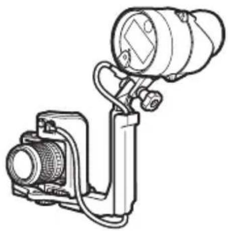
natural_image
Technical line drawing of a camera or optical instrument with lens and mounted components (no text or symbols)natural_image
Illustration of a hand holding a camera with a mounted device and screen, no text or symbols presentnatural_image
Technical line drawings of four mechanical components: a camera, a lens, a spring-loaded bracket, and a separate clamp (no text or symbols present)natural_image
Illustration of a hand holding a magnifying glass over a clipboard with tools, alongside a separate view of a mechanical clamp (no text or symbols present)4 風通しのよい日陰で乾燥させる
natural_image
Illustration of mechanical components including a clamp, bracket, and tool (no text or symbols)natural_image
Technical illustration of a mechanical device with a cylindrical component and a separate motor housing (no text or symbols)Jp
メンテナンス
0リングのお手入れについて
natural_image
Diagram of hands performing a mechanical operation with arrows indicating motion (no text or symbols present)2 真水でよく洗う
natural_image
Line drawing of two hands holding a curved object, no text or symbols present40 リング溝を点検する
natural_image
Diagram of a hand holding a tool interacting with a mechanical component (no text or symbols visible)50 リングに専用シリコングリスを塗る
natural_image
Illustration of two hands holding a smartphone with a circular lens and motion lines (no text or symbols)Jp
natural_image
Mechanical component diagram showing a piston and housing assembly with no visible text or symbolsVO リングについて
- http://www.nikon-image.com/support/repair/
SB-N10 Underwater Speedlight
User's Manual
The SB-N10 underwater speedlight (fl ash unit) is for use with WP-N1, WP-N2, and WP-N3 waterproof cases and Nikon 1 AW1 cameras. Keep this manual where all those who use the product will read it, and be sure to read both it and the camera manual thoroughly before use.
Symbols and Conventions
To make it easier to find the information you need, the following symbols and conventions are used:

This icon marks cautions, information that should be read before use to prevent damage to the camera or flash unit.

This icon marks notes, information that should be read before using the product.

This icon marks references to other pages in this manual.
√ Important: Read Before Use
Before using the equipment in or near water, test for leaks as described on page 19 of this manual.

For Your Safety
Before using this product for the first time, read the safety instructions in "For Your Safety" (v–xiv).
Table of Contents
For Your Safety ....V
Introduction .... 1
Package Contents....1
Required Accessories....2
Parts of the SB-N10 3
Readying the Unit for Use....7
Inserting Batteries 7
Attaching an Underwater Bracket 10
Pre-Dive Preparation....18
The Pre-Dive Checklist....18
The Final Check 19
Flash Photography 22
TTL Flash Control 22
Using TTL Flash Control with the AW1, J4, and S2 ....22
Using TTL Flash Control with the J1, J2, J3, and S1 ....24
Manual Flash Control....26
Using the Targeting Lamp 28
The Underwater Wide-Flash Adapter....29
Attaching the Strap 29
Attaching and Removing the Adapter....30
After Use 31
Maintenance....34
Caring for the O-Ring 34
Maintenance and Storage....37
Troubleshooting 38
Specifications....40
Accessories Available for Separate Purchase....41
En
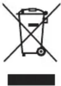
Notice for Customers in Europe
This symbol indicates that electrical and electronic equipment is to be collected separately.
natural_image
Symbol of a trash bin crossed with no text or labels, accompanied by a horizontal line and a solid rectangle below (no text or symbols present)The following apply only to users in European countries:
• This product is designated for separate collection at
an appropriate collection point. Do not dispose of as household waste.
- Separate collection and recycling helps conserve natural resources and prevent negative consequences for human health and the environment that might result from incorrect disposal.
- For more information, contact the retailer or the local authorities in charge of waste management.

Life-Long Learning
As part of Nikon's "Life-Long Learning" commitment to ongoing product support and education, continually-updated information is available online at the following sites:
- For users in the U.S.A.: http://www.nikonusa.com/
- For users in Europe and Africa: http://www.europe-nikon.com/support/
- For users in Asia, Oceania, and the Middle East: http://www.nikon-asia.com/
Visit these sites to keep up-to-date with the latest product information, tips, answers to frequently-asked questions (FAQs), and general advice on digital imaging and photography. Additional information may be available from the Nikon representative in your area. See the following URL for contact information: http://imaging.nikon.com/
ForYourSafety
To prevent damage to your Nikon product or injury to yourself or to others, read the following safety precautions in their entirety before using this equipment. Keep these safety instructions where all those who use the product will read them.
The consequences that could result from failure to observe the precautions listed in this section are indicated by the following symbol:
This icon marks warnings. To prevent possible injury, read all warnings before using this Nikon product.
■ WARNINGS
Turn off in the event of malfunction. Should you notice smoke or an unusual smell coming from the unit, remove the batteries immediately, taking care to avoid burns. Continued operation could result in injury. After removing the power source, take the unit to a Nikon-authorized service representative for inspection.
Do not disassemble or subject to powerful physical shocks. Touching the unit's internal parts could result in injury. Repairs should be performed only by qualified technicians. Should the unit break open as the result of a fall or other accident, take it to a Nikon-authorized service representative for inspection, after disconnecting the unit from the camera and/or removing the batteries.
Keep the unit watertight. Only immerse if the battery holder is in place. Do not clean the unit with a high-pressure jet. Do not remove the battery holder in locations exposed to dust or sand, and be sure to remove any foreign objects from the O-ring and any parts of the unit that are in contact with the O-ring before inserting the holder. The entry of water into the unit could result in fire or electric shock or expose the operator to toxic gases; should water enter the unit, remove the batteries and cease use immediately.
Do not use in the presence of flammable gas or dust. Use of electronic equipment in the presence of flammable gas or dust could result in explosion or fire.
⚠️ Observe caution when using the flash.
- Using a flash in close contact with the skin or other objects could cause burns.
- Using the flash close to the subject's eyes could cause temporary visual impairment. Stay at least 1 m (3 ft 4 in.) from the subject when using the flash.
- Do not aim the flash at the operator of a motor vehicle. Failure to observe this precaution could result in accidents.
⚠️ Keep out of reach of children. Failure to observe this precaution could result in injury. In addition, note that batteries and other small parts constitute a choking hazard. Should a child swallow any part of this equipment, consult a physician immediately.
Do not dive while holding. To prevent injury caused by blows from the equipment, do not hold it while jumping or diving into water.
⚠ Do not eat silicon grease. Silicon grease is not edible.
Do not handle the unit with wet hands unless the battery holder is in place. Failure to observe this precaution could result in electric shock.
⚠️ Observe caution when handling batteries. Batteries may leak, overheat, or rupture if improperly handled. When handling batteries for use in this product, follow all instructions and warnings printed on or included with the batteries and observe the following precautions:
- Use only the types listed in this manual. Do not combine old and new batteries or batteries of different makes or types.
- Do not attempt to recharge non-rechargeable batteries. When re-charging NiMH batteries, follow instructions and use compatible chargers only.
- Insert batteries in the correct orientation.
- Batteries may become hot if the flash is fired multiple times in quick succession. When removing the batteries, take precautions to avoid burns.
- Do not short or disassemble batteries or attempt to remove or otherwise damage the battery insulation or casing.
- Do not expose to flame or excessive heat, immerse in or expose to water, or subject to physical force.
- Do not transport or store with metal objects such as necklaces or hairpins.
- Batteries are prone to leakage when fully discharged. To avoid damage to the product, be sure to remove the batteries when no charge remains or if the product will not be used for an extended period.
- Discontinue use immediately should you notice any change in the batteries, such as discoloration or deformation.
- To prevent infl ammation should liquid from damaged batteries contact clothing, eyes, or skin, immediately rinse the affected area with clean water and contact a physician.
- Dispose of used batteries in accord with local regulations. To prevent fire, overheating, or rupture caused by contact with metal objects, insulate the terminals with tape prior to disposal.
Do not clean with organic solvents such as paint thinner or benzene, spray with insecticide, or store with naphtha, or camphor moth balls. Failure to observe this precaution could damage or discolor the unit's plastic parts.
⚠️ Follow the instructions of airline and hospital personnel. Radio-frequency noise emitted by this unit when it is in operation may interfere with medical equipment or aircraft navigation. Turn the unit off during take off and landing and follow all instructions of airline and hospital personnel.
Do not remain in contact with the unit for extended periods while it is on or in use. Parts of the unit become hot. Leaving the unit in direct contact with the skin for extended periods may result in low-temperature burns.
Do not suspend heavy objects from the unit. When picking up or carrying the waterproof case or camera, do not hold the camera or case by the unit or accessories attached to the unit. The camera or case might fall, resulting in injury or damage to the equipment.
Do not expose to high temperatures. Do not use the unit in water warmer than 40 °C (104 °F) or leave it in locations exposed to high temperatures, such as in direct sunlight or an enclosed vehicle. Excessive heat could deform the casing, resulting in water entry, fire, or malfunction.
Do not use at depths greater than 100 m (328 ft). Failure to observe this precaution could result in water entry or malfunction.
Cautions
To ensure continued enjoyment of your Nikon product, observe the following precautions when storing or using the device.
Waterproofing
Observe the following precautions when using the unit in or around water:
- The unit is proof only against fresh water (such as pools, rivers, and lakes) and seawater. Do not take into hot springs or baths.
- Do not expose to depths greater than 100 m (328 ft) or to rapids, waterfalls, water flowing at full force from a tap, or other water under high pressure. Failure to observe these precautions could expose the unit to pressures high enough to cause water entry.
- Exposure to water will damage the unit's internal parts. To prevent water entry, do not remove the battery holder with wet hands, when the unit is wet, or in locations exposed to spray, wind, sand or dust. Ensure that batteries are dry before insertion. Should the unit leak, cease use immediately, dry it off, and consult a Nikon-authorized service representative.
- Water and other liquids on the O-ring guide or the bottom or sides of the battery holder should be removed immediately with a soft, dry cloth. Other foreign matter should be removed from these surfaces with a blower, taking care to remove any small particles from the sides and corners of the O-ring guide. Foreign matter on the exterior of the unit can be removed with a soft, dry cloth. Do not use soap, cleansers, or other chemicals, and be sure to remove suntan oil, sunblock, bath salts, detergent, soap, organic solvents, oil, alcohol, and the like immediately.
-
Do not leave the unit for extended periods in locations that are exposed to freezing temperatures or temperatures over 60 °C (140 °F), such as in enclosed vehicles, on board boats, on the beach, in direct sunlight, or near heating equipment. Failure to observe this precaution may make the unit vulnerable to water entry.
-
The unit is not guaranteed waterproof if struck, dropped, placed under heavy objects, or otherwise subjected to strong pressure or violent physical shocks or vibration. If the unit does suffer a fall or other physical shock, take it to Nikon-authorized service personnel and have it tested to make sure that it is still waterproof. Note that a fee will be charged for this service.
- Damage due to user error is not covered under warranty.
■ Operating Environment
The unit has been tested and approved for use at water temperatures between 0 °C and 40 °C ( 32 °F to 104 °F ). Note the following precautions:
- At low temperatures, the flash may not perform as expected immediately after being turned on and battery performance may drop. Keep the unit warm, or ready spare batteries and keep them in a warm location.
- In cold environments, remove any snow or rain immediately. The controls may become difficult to operate if allowed to freeze.
- Prolonged contact with cold metal can damage exposed skin. Wear gloves when handling the unit for extended periods at low temperatures.
- Select a dry location when replacing batteries, and avoid leaving the unit with the battery holder removed in humid locations. Failure to observe these precautions could result in condensation forming inside the unit when it is taken into the water. Any condensation should dissipate if the unit is first taken to a location with a stable temperature—free from heat, humidity, sand, and dust—and then turned off and left with the battery holder removed until it has reached the ambient temperature.
■ Using the Flash Unit
Observe the following precautions when using the flash unit:
- Remove the batteries for storage or transport. If the batteries are left in place, the unit may turn on accidentally, causing fire.
- Pressure may increase inside the unit during underwater use. This may cause water to spurt from the unit or the holder to fly off when unlatched, resulting in injury.
- Do not use the unit while operating a vehicle. Failure to observe this precaution could result in accidents.
- The unit may not perform as expected in the vicinity of powerful magnetic fields.
- Rinse the unit in fresh water after use, being careful not to compromise the waterproof seal (☐ 31). Dry it with a soft, dry cloth and be sure that all droplets have been removed before leaving it unattended. Water droplets may leave stains if allowed to evaporate in place. After removing all visible water, leave the unit in a shady, well-ventilated area to dry.
- To protect the unit from mold, mildew, corrosion, and rust, avoid storing it in locations that are damp or exposed to high levels of humidity. Failure to observe this precaution could result in malfunction.
- Take the unit from storage about once a month, insert the batteries, fi re it, and test the controls. Before returning the unit to storage, confi rm that the fl ash-ready lamp is lit, and then turn the unit off and remove the batteries.
■ Batteries
Observe the following precautions when handling batteries for use in this unit:
- The large amounts of current used by the flash may result in rechargeable batteries becoming unusable before reaching the manufacturer's stated recharge/discharge limit.
- When replacing the batteries, turn the unit off and insert the replacement batteries in the correct orientation.
- Dirt on the battery terminals can interrupt the flow of current. Clean dirt from the terminals before inserting the batteries.
- After being fi red multiple times in quick succession, the fl ash may stop fi ring to allow the batteries to cool. Normal operation can be resumed once the batteries have cooled sufficiently.
- Batteries tend to lose capacity at low temperatures, recover lost voltage when allowed to rest, and slowly discharge when not in use. Be sure to check the battery level before use and replace the batteries before they are fully discharged.
- Do not store batteries in locations subject to high temperatures or high humidity.
- For information on handling and recharging rechargeable batteries, see the documentation provided by the manufacturers of the batteries and the battery charger.
- Do not attempt to recharge non-rechargeable batteries. Failure to observe this precaution could cause the batteries to rupture.

Ni-MH
Recycling rechargeable batteries
Used batteries are a valuable resource; to protect the environment, recycle used batteries in accord with local regulations.
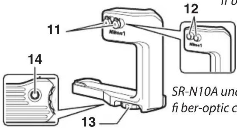
■ Optional SC-N10A Underwater Fiber-Optic Cables
Observe the following precautions when using SC-N10A underwater fiber-optic cables:
- The SC-N10A transmits the light produced by the camera's built-in flash to the SB-N10 and is for use with the SB-N10 and WP-N1, WP-N2, and WP-N3 waterproof cases or SR-N10A underwater fi ber-optic cable adapters. Do not attempt to use the cable with incompatible devices. Failure to observe this precaution could damage the cable.
- Do not forcibly bend the cable or place it under heavy objects. Either action could damage the cable, resulting in malfunction.
- When connecting or disconnecting the cable, hold it by the connectors. Tugging directly on the cable could result in malfunction.
- Keep the connectors clean. Dirt on the connectors could interfere with the transmission of data between the camera and flash unit, causing the flash to malfunction. Before use, check the connectors for salt, sand, or other foreign matter and if necessary clean them in fresh water. After use, disconnect the flash unit and waterproof case or underwater flash ber-
optic cable adapter and rinse the cable in fresh water.
- If you have diffi culty inserting or removing the connector, lightly lubricate the connector O-ring with silicon grease. To remove a stuck connector, twist it out gently; do not use force. If, on the other hand, the connector pulls out too easily, remove excess grease using a cloth or similar object.
- Contact a Nikon-authorized service representative should you notice that the O-ring seal is cracked, deformed, or otherwise damaged.
- Do not disassemble or modify. Failure to observe this precaution will void the warranty and may cause malfunction. Repairs and internal inspection must be performed only by Nikon-authorized service representatives.
■ Optional SK-N10A Underwater Brackets
Observe the following precautions when using an optional underwater bracket:
- The SK-N10A is for use with the SB-N10 and WP-N1, WP-N2, and WP-N3 waterproof cases or SR-N10A underwater fiber-optic cable adapters. Attach the equipment securely to the bracket to prevent damage and loss, but do not use excessive force. Failure to observe this precaution could damage the case, allowing water entry, or result in injury, malfunction, or damage to the equipment.
- To prevent damage to or loss of items mounted on the bracket, tighten lock screws immediately should they loosen during use.
- Keep lock screws free of sand, dust, and other foreign matter and choose a sand- and dust-free location when attaching or removing items. Failure to observe this precaution could interfere with proper functioning of the screws.
- Do not disassemble or modify. Failure to observe this precaution will void the warranty and may cause result in water entry or damage to the equipment. Repairs and internal inspection must be performed only by Nikon-authorized service representatives.
- After use, remove the flash unit, fiber-optic cable, and waterproof case and rinse the bracket in fresh water.
- When lifting or transporting a waterproof case with the bracket attached, pick the bracket up by the grip, not the stay. Failure to observe this precaution could result in injury or damage to the equipment due to falls or other accidents.
■ Optional SR-N10A Underwater Fiber-Optic Cable Adapters
Observe the following precautions when using an optional fi ber-optic cable adapter:
- The SR-N10A attaches to Nikon 1 AW1 cameras equipped with waterproof lenses and connects to the SB-N10 via an SC-N10A underwater fiber-optic cable. Attach the camera and flash unit securely to the bracket to prevent damage and loss, but do not use excessive force. Failure to observe this precaution could damage the camera, allowing water entry, or result in injury, malfunction, or damage to the equipment.
- To prevent damage to or loss of items mounted on the bracket, tighten lock screws immediately should they loosen during use.
- Choose a sand- and dust-free location when attaching or removing the fiber-optic cable adapter. Sand or dust inside the adapter could make it difficult to secure in place.
- After use, disconnect the camera and fi ber-optic cable and rinse the fi ber-optic cable adapter in fresh water.
- Do not disassemble or modify. Failure to observe this precaution will void the warranty and may cause malfunction. Repairs and inspection must be performed only by Nikon-authorized service representatives.
Introduction
Refer to this section for the names of the supplied accessories and the parts of the SB-N10.
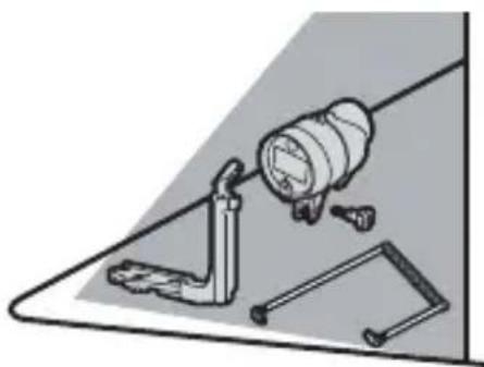
Package Contents
Confir rm that the package contains the items listed below. Contact your retailer if anything is missing.
natural_image
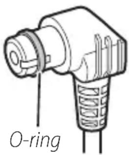
Line drawing of a cylindrical device with a rectangular component and mounting base (no text or symbols)☐ SB-N10 underwater speedlight (with WP-O3000 O-ring in place; before use, check that O-ring is undamaged as described on page 34)
□ Wide-fl ash adapter strap
□User's Manual (this manual)
□ Warranty
natural_image
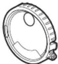
Technical line drawing of a mechanical component with no visible text or symbols□SW-N10A underwater wide-fl ash adapter
natural_image
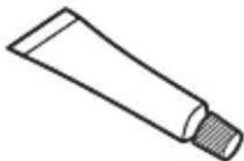
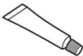
Simple line drawing of a cotton tube with a cork stopper (no text or symbols)□ WP-G1000 silicon grease
RequiredAccessories
The items listed below are sold separately and are required when the unit is used with a waterproof case or camera.
natural_image
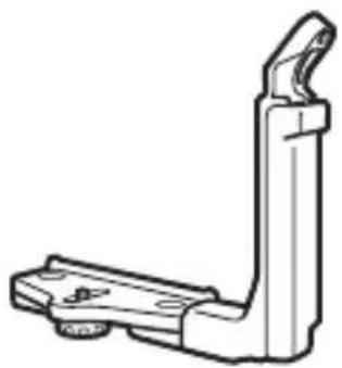
Technical line drawing of a mechanical bracket or clamp (no text or symbols)□ SK-N10A underwater bracket

natural_image
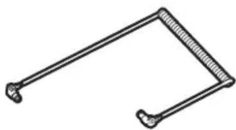
Simple line drawing of a mechanical linkage or bracket (no text or symbols)□ SC-N10A underwater fiber-optic cable
When using a WP-N1, WP-N2, or WP-N3 waterproof case, mount the case and SB-N10 on the SK-N10A and use the SC-N10A to connect the flash unit to the case (☐ 10).
natural_image
Line drawing of a handheld electronic device (no text or symbols)□SR-N10A underwater fi ber-optic cable adapter
When using a Nikon 1 AW1, mount the camera on an SK-N10A underwater bracket and connect the SB-N10 using the SR-N10A and an SC-N10A (☐ 14).
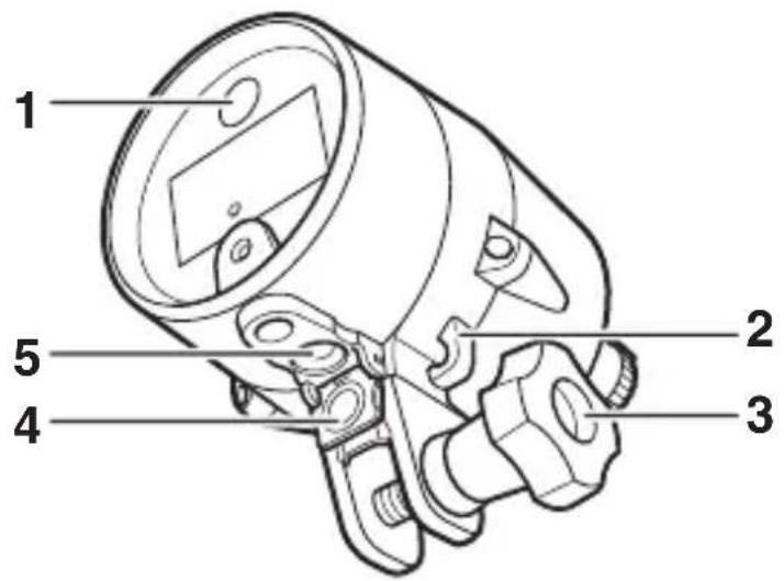
1 Targeting lamp ......28
2 Strap hook ......29
3 Mounting bolt 11, 15, 28
4 Sensor cover .....12, 16, 32
5 Fiber-optic connector .....12, 17
En
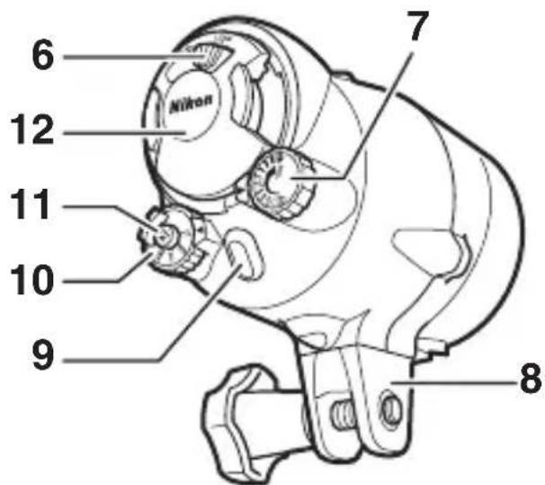
6 Battery-holder latch .... 7, 18
7 Flash-level dial .....4, 23, 27
8 Base
9 Flash-ready lamp ......6
10 Mode dial 4
11 Targeting lamp
button 5,23,24,28
12 Battery holder .....7, 18, 19, 31
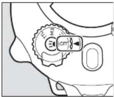
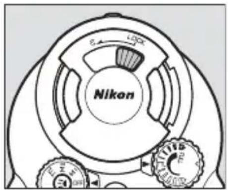
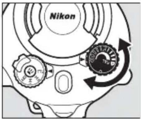
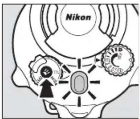
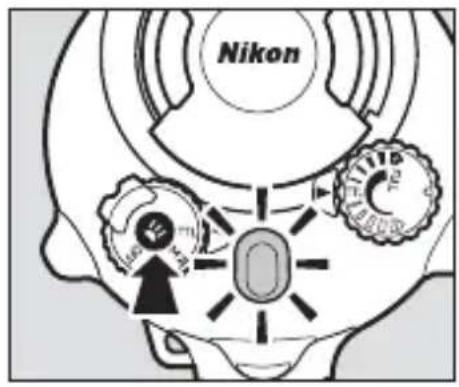
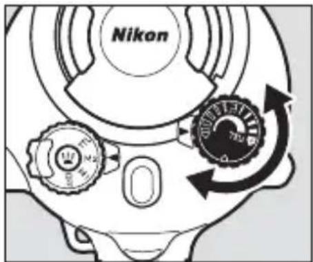
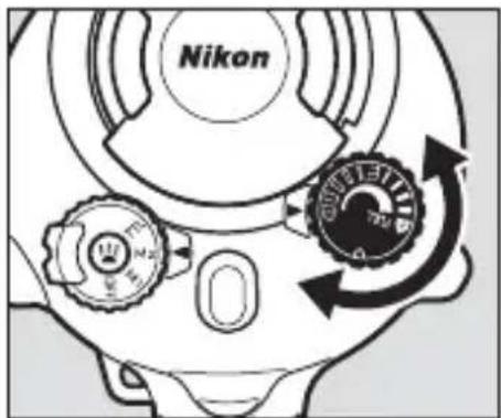
■ The Mode Dial
Choose a flash control mode:
• OFF: Turn the flash off.
- M1/M2: Manual flash control 26; not available with the J1, J2, J3, or S1).
- TTL:TTL flash control (22). Press the targeting lamp button to enable or disable flash-compensation support.
Auto Power Off
At settings other than OFF, the flash unit will turn off automatically 30 minutes after it was last fired. To turn it on again, rotate the mode dial to OFF and then select the desired mode.
■ The Flash-Level Dial
Use flash compensation (TTL mode) or choose the flash level (M1 and M2 modes, not available with the J1, J2, J3, or S1).
■ The Targeting Lamp Button
Turn the targeting lamp on or off or enable flash-compensation support.
- To turn the targeting lamp on or off (28), press the button for about a second and then release it. The lamp will turn off automatically when the flash fires.
- To disable or enable fl ash-compensation support (23, 24), select TTL mode and keep the button pressed until the fl ash-ready lamp changes color (about three seconds). The flash-ready lamp lights red when flash-compensation support is enabled and blue when flash-compensation support is disabled. If the flash unit is turned off, the most recently selected setting will be restored the next time the unit is turned on.

■ The Flash-Ready Lamp
View flash status.
En
| Lamp Status | |
| Lights red | Flash is charged and ready for use (does not apply if flash-compensation support is disabled). |
| Lights green for 2 s after flash fi res | Flash fi red in TTL mode. |
| Lights blue Flash | -compensation support disabled. |
| Blinks red and green | Batteries exhausted. Insert another set. |
| Blinks red or blue | Temperature warning. Wait for unit to cool before turning it off and then on again. |
Readying the Unit for Use
Read the manuals for the waterproof case and camera before proceeding.
■ The O-Ring
The O-ring keeps the unit watertight. Before using the flash, inspect and clean the ring and O-ring guide and lubricate the ring as described on pages 34–36.
En
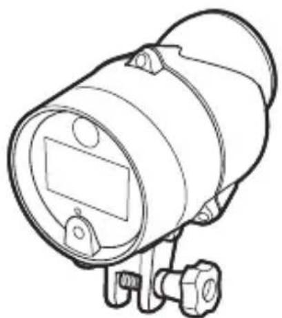
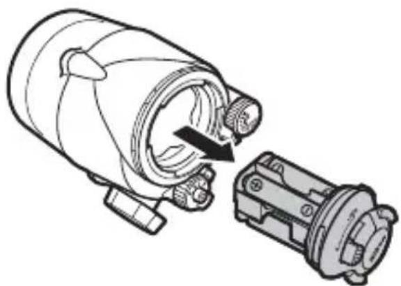
InsertingBatteries
The unit takes four AA alkaline or nickel-metal hydride (NiMH) batteries. Use new batteries only; do not combine old and new batteries or mix batteries of different makes or types.
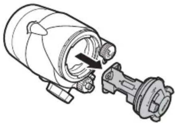
1 Turn the unit off.
Confir rm that the mode dial is ro- tated to OFF.
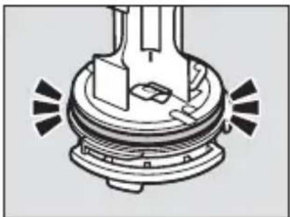
2 Unlatch the battery holder.
Keeping the latch pressed, slide it counterclockwise to the Ⓑ (un-latched) position.
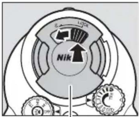
Battery holder
3 Remove the holder.
Slowly slide holder from the unit, keeping the holder straight and the unit horizontal to ensure that water does not drop into the interior.
natural_image
Technical line drawing of a mechanical device with a rotating shaft and housing (no text or symbols)4 Insert the batteries.
Insert the batteries in the orientation shown.
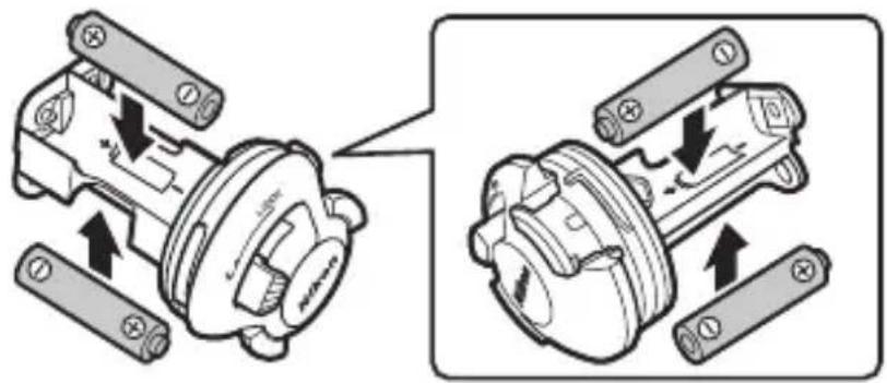
5 Replace the holder.
After confi rming that the latch is still in the unlatched posi-tion ( ), slide the holder into the unit as shown.
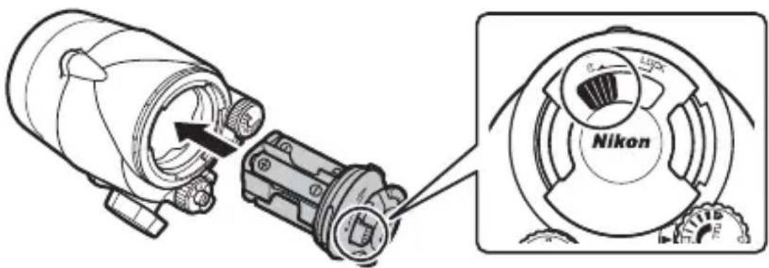
6 Latch the holder.
Keeping the latch pressed, slide it clockwise to the LOCK position.
Batteries
Replace the batteries if it takes more than 30 seconds for the flash-ready lamp to light red after the flash fires at full power. Before inserting and replacing batteries, wipe any water from the unit and be sure your hands are dry; during the procedure, be careful that no drops fall on or into the product from your hair or wet-suit. To prevent water entry, check that the battery holder is inserted and securely latched after replacing the batteries.
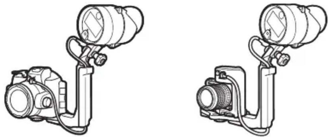
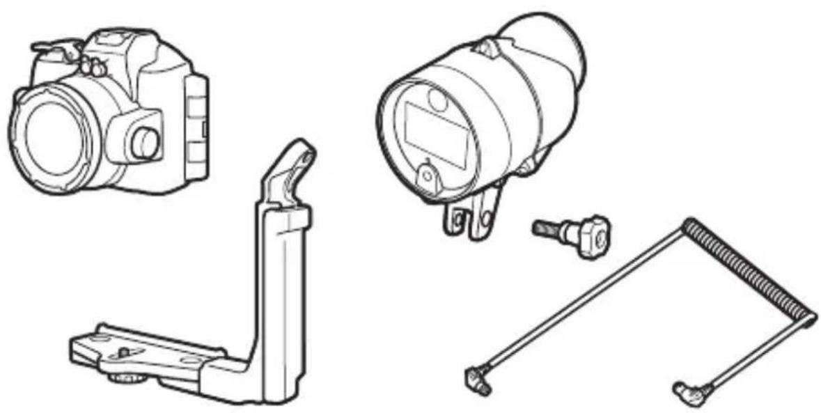
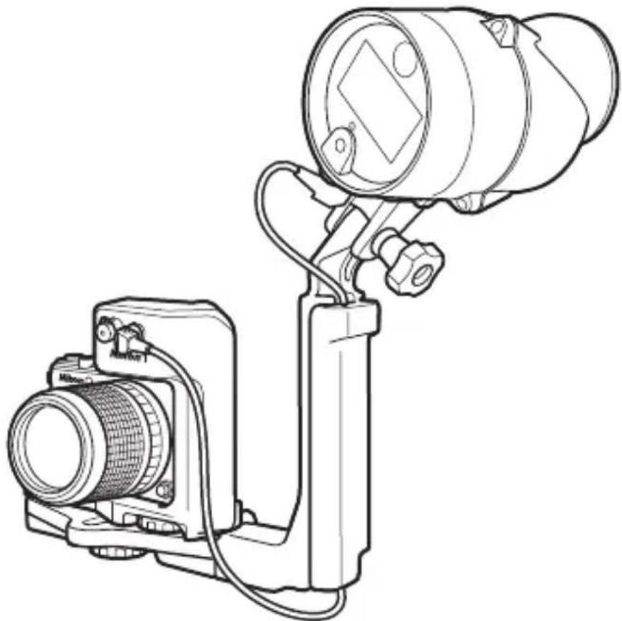
Attaching an Underwater Bracket
Attach an underwater bracket before using the equipment under water.
Waterproof Cases
If you are using a WP-N1, WP-N2, or WP-N3 waterproof case, mount the case and flash unit on an SK-N10A underwater bracket and connect them using an SC-N10A underwater fiber-optic cable (both available separately; 2).
En
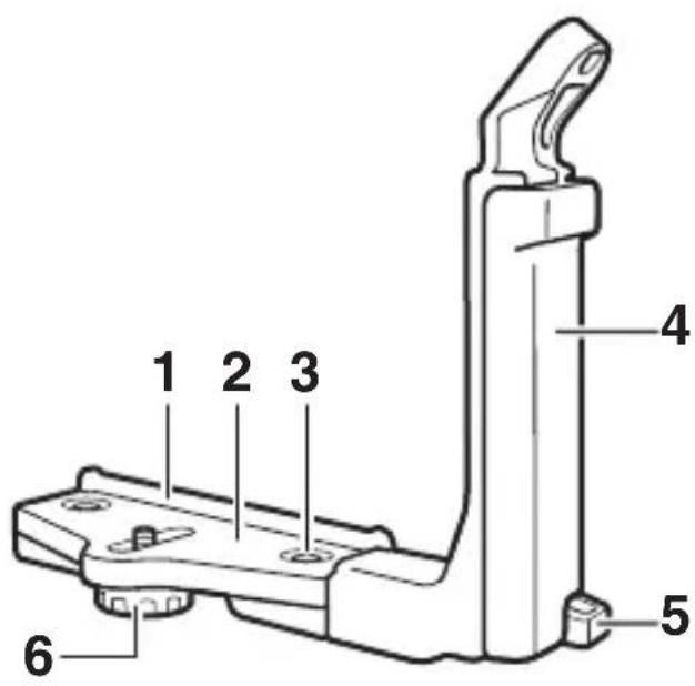
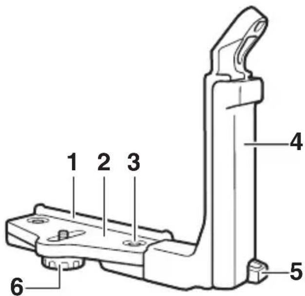
SK-N10A underwater bracket
SC-N10A underwater fi ber-optic cable
Mounting guide
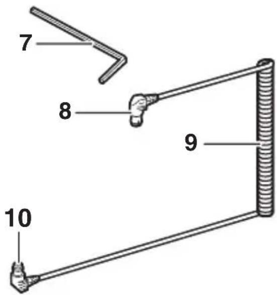
2 Stay
3 Grip lock screw
4 Grip
5 Strap hook
6 Case/adapter lock screw
7 M4 hex key
8 Connector (connects to SB-N10)
9 Cable
10 Connector (connects to case)
Before readying the equipment as described below, confirm that the camera's built-in flash is raised and that the camera and SB-N10 are off.
1 Attach the flash unit.
Mount the unit on the grip using the mounting bolt.
2 Place the waterproof case on the bracket.
Align tripod socket with the case/adapter lock screw and tighten the screw part way.
natural_image
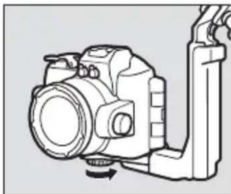
Diagram of a DSLR camera with a base mount and adjustment lever (no text or symbols)3 Position the waterproof case.
Slide the case until it contacts the stay mounting guide.
natural_image
Diagram of a digital camera module with a base case and control panel (no text or symbols)4 Tighten the lock screw.
Tighten the screw the rest of the way.
natural_image
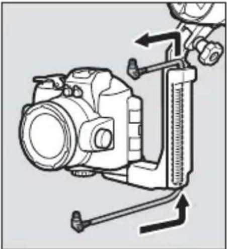
Line drawing of a DSLR camera with attached lever and base mount (no text or symbols)5 Pass the cable through the grip.
Pass the fi ber-optic cable through the grip from bottom to top as shown. The shorter of the cable's two straight sections should be at the top.
natural_image
Technical line drawing of a camera with attached caliper and adjustment knobs (no text or symbols)En
6 Open the sensor cover.
Open the flash unit sensor cover.
natural_image
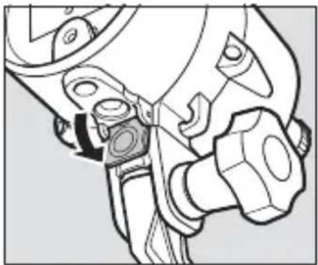
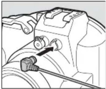
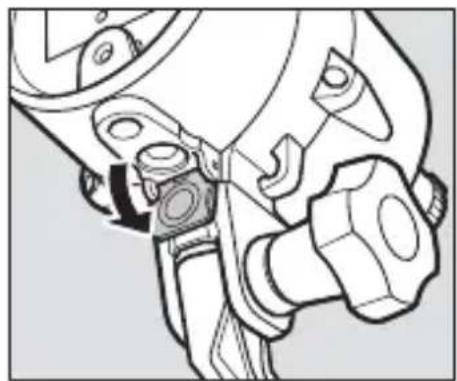
Technical line drawing of a mechanical assembly with no visible text or symbols7 Connect the cable to the flash unit.
Insert the top connector securely into the flash unit's fi ber-optic connector.
natural_image
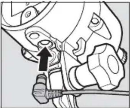
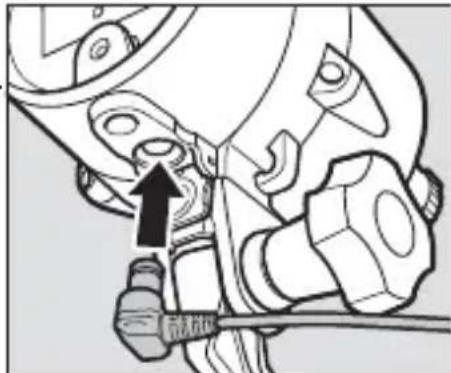
Mechanical assembly diagram showing a tool interacting with a mechanical component (no text or symbols visible)8 Connect the cable to the waterproof case.
Insert the bottom connector into the fi ber-optic connector on the case.
natural_image
Mechanical assembly diagram showing a valve mechanism with a connector (no text or symbols visible)
natural_image
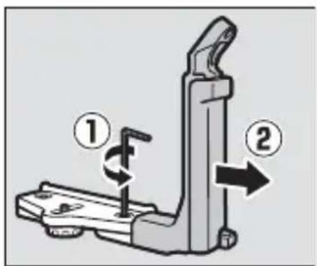
Line drawing of a DSLR camera with attached optical lens (no text or symbols)To remove equipment from the bracket, reverse the above steps. To remove the grip and stay, use the supplied hex key to loosen the grip lock screw as shown.
■ Nikon 1 AW1 Cameras
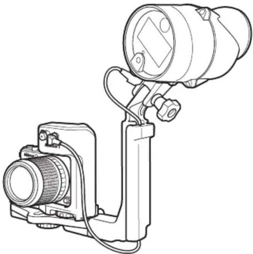
If you are using a Nikon 1 AW1, mount the camera and flash unit on an optional SK-N10A underwater bracket and connect them using an SC-N10A underwater fiber-optic cable and SR-N10A underwater fiber-optic cable adapter (both available separately; 2).
En
SK-N10A underwater bracket
SC-N10A underwater
fi ber-optic cable
1 Mounting guide
2 Stay
3 Grip lock screw
4 Grip
5 Strap hook
6 Case/adapter lock screw
7 M4 hex key
8 Connector (connects to SB-N10)
9 Cable
10 Connector (connects to adapter)
Fiber-optic connector caps
12 Fiber-optic connector
13 Camera lock screw
14 Adapter lock screw socket
Before readying the equipment as described below, confirm that the camera and SB-N10 are off.
1 Ready the camera.
Attach a waterproof lens and raise the built-in flash.
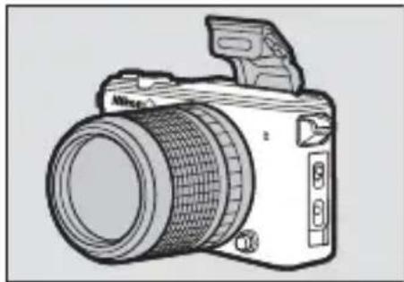
natural_image
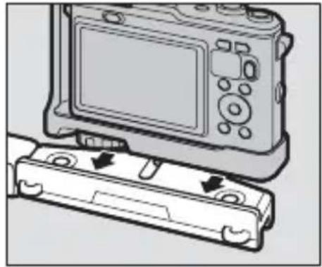
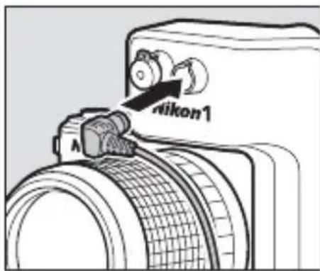
Line drawing of a DSLR camera with lens and external handle (no text or symbols)2 Attach the fi ber-optic cable adapter.
Being careful not to press the lens release button, align tripod socket with the camera lock screw and tighten the screw to fix the adapter in place.
natural_image
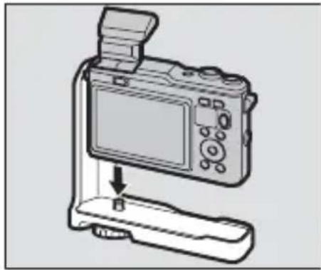
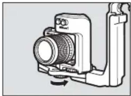
Line drawing of a digital camera with an attached base and a screen, showing no text or symbols.3 Attach the flash unit.
Mount the unit on the grip using the mounting bolt.
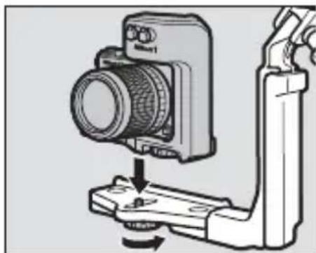
4 Place the camera/adapter assembly on the bracket.
Align the adapter lock screw socket with the case/adapter lock screw and tighten the screw part way.
natural_image
Diagram of a camera assembly with a mounted lens and base mount (no text or symbols)5 Position the camera/adapter assembly.
Slide the assembly until it contacts the stay mounting guide.
natural_image
Diagram of a digital camera module with two buttons and a display screen, showing no text or symbols.6 Tighten the case/adapter lock screw.
Tighten the screw the rest of the way.
natural_image
Technical line drawing of a camera module with no visible text or symbols7 Pass the cable through the grip.
Pass the fi ber-optic cable through the grip from bottom to top as shown. The shorter of the cable's two straight sections should be at the top.
natural_image
Technical line drawing of a camera with attached lever and adjustment knobs (no text or symbols)8 Open the sensor cover.
Open the flash unit sensor cover.
natural_image
Technical line drawing of a mechanical assembly with no visible text or symbols9 Connect the cable to the flash unit.
Insert one of the two connectors securely into the flash unit's fiber-optic connector.
natural_image
Mechanical assembly diagram showing a tool interacting with a component (no text or symbols visible)10 Connect the cable to the adapter.
Insert the remaining connector into a fi ber-optic connector on the adapter.
natural_image
Technical line drawing of a camera setup with lens, camera body, and mounted device (no text or symbols)To remove equipment from the bracket, reverse the above steps.
Pre-Dive Preparation
Before using the equipment underwater, check that the unit is watertight and ready for use.
The Pre-Dive Checklist
Check the following before taking the unit into the water:
Is the camera's built-in flash raised?
□ Is the equipment securely attached to the bracket (10, 14)?
□ Is the fiber-optic cable securely connected (12, 17)?
☐ Is the unit watertight? To ensure that the unit is watertight:
- Remove any sand, dust, hair, and other foreign matter from the bottom and sides of the battery holder.
- Use a blower or cotton swab to remove any sand, dust, hair, and foreign matter from inside the flash unit (when using a cotton swab, be sure not to leave any threads behind).
- Check the O-ring for cracks and replace if necessary.
- Confirm that the battery holder is secured with the latch in the LOCK position.
The Final Check
This section describes how to perform a pre-dive check after attaching the SB-N10. For information on performing pre-dive checks on the Nikon 1 AW1 or a waterproof case, see the manuals provided with the camera or case.
After completing the checklist on page 18 and confi rming that the battery holder is securely inserted and latched, fi ll a bucket or other container with fresh water, immerse the assembly, and confi rm that no air escapes. Should you notice air escaping, immediately remove the assembly from the water, dry
it thoroughly, and check the watertight seals. If the cause of the leak can not be determined, contact a Nikon-authorized service representative.
natural_image
Illustration of a hand holding a camera with a mounted device (no text or symbols visible)

Cautions
To prevent water entry or other damage, observe the following precautions when using the unit under water:
- Never remove the battery holder under water. Before removing the holder, wipe off water with a soft, dry cloth and be sure the unit is completely dry. Choose shaded locations free from spray, wind, dust, sand, and the risk of fire, and check for water on the sides or bottom of the holder before insertion. Water inside the unit could result in condensation or other damage, while water on the battery holder terminals or batteries could result in corrosion or overheating.
- The sudden change in temperature caused by taking the unit into the water after it has been left on the beach, in direct sunlight, or in other locations exposed to high temperatures could result in water droplets forming inside the device, potentially damaging it.
- Do not expose the unit to depths greater than 100 m (328 ft) or to rapids, waterfalls, water flowing at full force from a tap, or other water under high pressure. Failure to observe these precautions could expose the unit to pressures high enough to cause water entry.
- Do not expose the unit to water colder than 0^ C (32°F) or warmer than 40^ C (104°F). Do not take into hot springs or baths.
- Do not touch the flash window while the flash is firing or immediately after it has fired.
- Do not dive into the water with the unit, drop it, place it under heavy objects, or otherwise subject it to violent shocks or excessive physical pressure or force. The unit may deform and become vulnerable to leaks under excessive external pressure.
- Failure to follow correct procedures before or during use could result in irreparable damage to the unit due to water entry. Should the unit leak, cease use immediately, dry the unit, and consult a Nikon-authorized service representative.

Cautions
- The unit does not float. Be careful not to drop it while in or on the water.
- Do not leave the unit in direct sunlight, an enclosed vehicle on hot days, the trunk or boot of a car, or other locations that may be exposed to extremely high temperatures. Increases in internal pressure or warping of plastic parts could deform the unit, causing water entry or condensation or damaging internal mechanisms and causing fire or electric shock.
En
Flash Photography
Follow the instructions in this section to take pictures using the flash. Note that the underwater flash unit will only fire when the camera's built-in flash fi res; adjust camera settings to disable the camera AF-assist illuminator and ensure the flash will fire with every shot. See the camera manual for details.
TTL Flash Control
In TTL mode, flash output is adjusted automatically in response to shooting conditions. The procedure for using TTL flash control varies with the model of camera.
■ Using TTL Flash Control with the AW1, J4, and S2
Follow the steps below.
1 Adjust camera settings.
Adjust camera settings as follows.
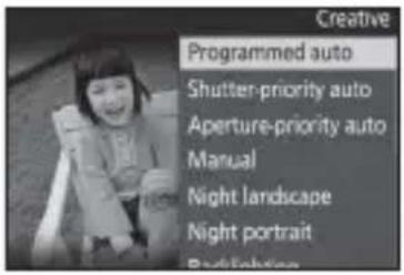
- Shooting mode: Choose P, S, A, or M, or choose C mode and select Underwater (AW1 only).
- Flash control: Select TTL for Flash control in the shooting menu.
- Underwater flash: Select Enable for Underwater flash in the shooting menu (users of the AW1 should note that this option is only available from camera firmware version 1.10).
- Flash mode: Choose a setting that disables red-eye reduction and ensures that the flash will fire with every shot.

natural_image
Black-and-white photo of a smiling child sitting in a chair, with no visible text or symbols on the image itself.

2 Adjustfl ash unit settings.
Rotate the mode dial to TTL.
3 Takepictures.
If fl ash output was adjusted successfully, the fl ash-ready lamp will light green for about two seconds after the fl ash has fi red. If the lamp does not light, adjust the distance to the subject and try again.
Flash output can be adjusted using the fl ash-level dial. Rotate the dial clockwise to increase fl ash output, counterclockwise to decrease.

If the Flash-Ready Lamp Lights Blue
If the fl ash-ready lamp lights blue, press the targeting lamp button until the lamp changes color (about three seconds) to show that fl ash-compensation support is enabled (☐ 5).
Disabling the Flash
The flash can be disabled by rotating the mode dial to OFF and setting the camera flash mode to ⏻ (off).
■ Using TTL Flash Control with the J1, J2, J3, and S1
Follow the steps below to take pictures in TTL flash control mode.
1 Adjust camera settings.
Adjust camera settings as follows.
- Shooting mode: Choose programmed auto (P), shutter-priority auto (S), aperture-priority auto (A), or manual (M).
- Flash mode: Choose a setting that disables red-eye reduction and ensures that the flash will fire with every shot.
2 Set the flash unit to TTL.
Rotate the mode dial to TTL and confirm that the flash-ready lamp is lit blue. If it is not, keep the targeting lamp button pressed until the lamp lights blue (about three seconds) to show that flash-compensation support is disabled (5).
3 Take pictures.

The J1, J2, J3, and S1
If you are using the unit with a J1, J2, J3, or S1, be sure to disable fl ash-compensation support. If the fl ash-ready lamp is lit red, press the targeting lamp button until the fl ash-ready lamp lights blue (about three seconds). The fl ash may fail to synchronize correctly if fl ash-compensation support is enabled.

Flash-Compensation Support
When flash-compensation support is disabled, flash level can not be adjusted using the flash-level dial and the flash-ready lamp does not light green after the flash fires.

Disabling the Flash
The flash can be disabled by rotating the mode dial to OFF and setting the camera flash mode to (off; but note that can not be selected when the built-in flash for the J1 or J2 is raised).
Manual Flash Control
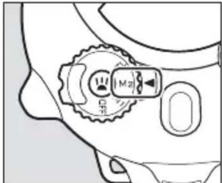
Users of the AW1, J4, and S2 can rotate the fl ash unit mode dial to M2 for manual flash control, allowing flash output to be selected directly using the fl ash-level dial.
1 Adjust camera settings.
Adjust camera settings as follows.
- Shooting mode: Choose P, S, A, or M, or choose C mode and select Underwater (AW1 only).
- Flash control: Select Manual for Flash control in the shooting menu. We recommend setting flash output to the minimum level to reduce the drain on the camera batteries.
- Underwater flash: Select Enable for Underwater flash in the shooting menu (users of the AW1 should note that this option is only available from camera firmware version 1.10).
- Flash mode: Choose a setting that disables red-eye reduction and ensures that the flash will fire with every shot.

natural_image
Black-and-white photo of a smiling child sitting on a chair, with no visible text or symbols in the main image area.

2 Adjustfl ash unit settings.
Rotate the mode dial to M2 and use the fl ash-level dial to choose the fl ash level.
3 Take pictures.

Flash Level
Depending on camera settings and shooting conditions, adjustments to flash level using the flash-level dial may not have the desired effect.

M1 Mode
When TTL is selected for Flash control in the camera shooting menu and the SB-N10 mode dial is rotated to M1, flash output can be set manually using the flash-level dial, but note that there may be a slight delay before the flash fires.

Disabling the Flash
The flash can be disabled by rotating the mode dial to OFF and setting the camera flash mode to ⏻ (off).
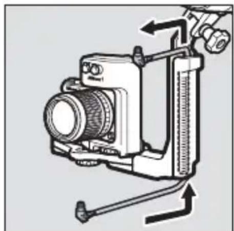
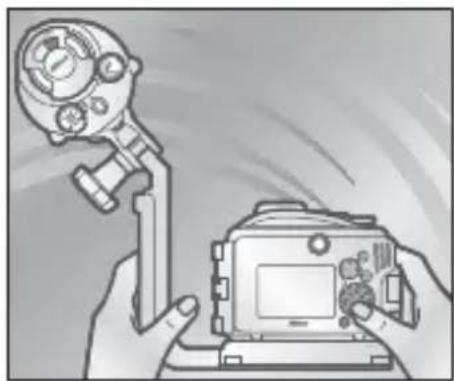
Using the Targeting Lamp
To use the targeting lamp, press the targeting lamp button.
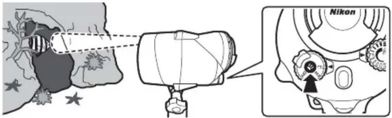
En
The targeting lamp shows where the flash is pointing and can be used to assist the focus operation when the subject is in shadow. The direction of the flash can be adjusted as shown below.
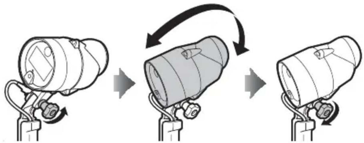
flowchart
graph TD
    A["Top Device"] --> B["Assembly Step"]
    B --> C["Bottom Product"]
Loosen mounting bolt Position flash unit Tighten mounting bolt
The Targeting Lamp
The lamp remains on until the targeting lamp button is pressed again or the flash unit is turned off. In M1 mode or when flash-compensation support is enabled, the lamp will turn off briefly when the flash fires.
The targeting lamp may flicker at low battery levels. This is not a malfunction.
The Underwater Wide-Flash Adapter
Using the underwater wide-fl ash adapter increases the vertical and horizontal angle illumination to 110^ , diff using the fl ash and illuminating a wider area. When used with the adapter, the fl ash has a guide number of 20/66 (m/ft). Depending on the lens, vignetting may occur at some focal lengths; take a test shot to determine the area illuminated by the fl ash.
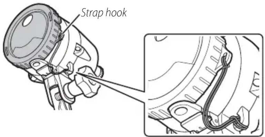
Attaching the Strap
Attach the strap to the adapter and flash unit.
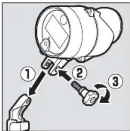
Attaching and Removing the Adapter
Attach or remove the adapter as described below.
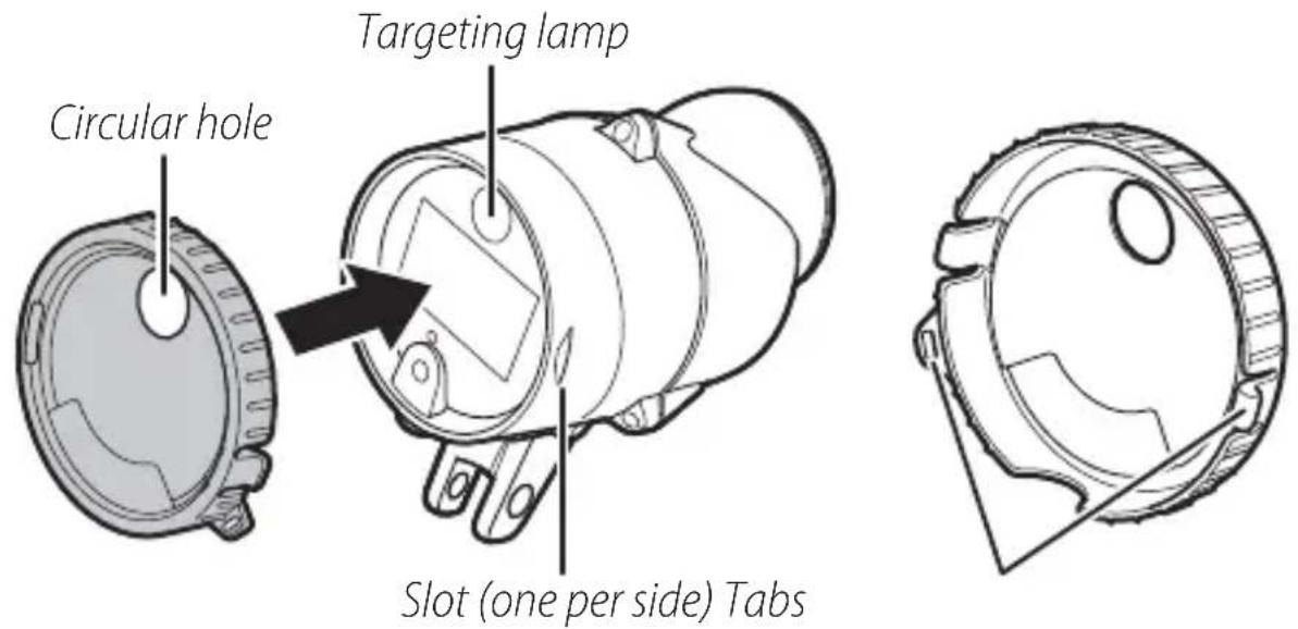
■ Attaching the Adapter
Position the adapter with the circular hole over the targeting lamp and slide the tabs into the matching slots on the sides of the flash unit, stopping when the adapter clicks into place.
Attaching the Underwater Wide-Flash Adapter
Attach the adapter securely to prevent it being damaged or lost.
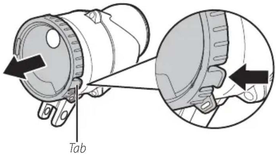
■ Removing the Adapter
Pop the tabs from the slots and then pull the adapter from the flash unit.
AfterUse
The unit should be cleaned after underwater use. Failure to observe this precaution could result in damage, discoloration, corrosion, off ensive odors, or vulnerability to leaks.

Before Cleaning the Unit
Clean the unit indoors in areas not exposed to sand or spray and be sure to remove any water, salt, sand, or other foreign matter from your hands or hair before proceeding. Do not remove the battery holder until all foreign matter has been washed away and the unit is dry.
1 Ready the unit.
Disconnect the fi ber-optic cable and remove the fl ash unit and waterproof case or camera from the bracket. For information on cleaning the waterproof case or camera, refer to the product manuals.
natural_image
Technical line drawings of four different mechanical components: a camera, a lens, a spring-loaded bracket, and a separate bracket (no text or symbols present)En
2 Immerse the unit.
After confi rming that the battery holder is inserted and se- surely latched, immerse the unit in a basin of fresh water. To prevent water entry and other damage, do not remove the battery holder while the unit is immersed.
Salt Damage
Leaving the unit immersed for too short a time could result in salt crystals forming when the unit dries. Such crystals are hard to remove and may impair the waterproof seal, resulting in water leaking into the unit. Always immerse the unit in fresh water and rinse it thoroughly to remove salt after use.
3 Clean the controls.
Gently move the unit side to side, then open and close the sensor cover and operate the controls a few times to remove salt and other foreign objects.
4 Wipe dry.
Dry the unit thoroughly with a soft, dry cloth. Do not use a cloth to which salt has adhered.
natural_image
Illustration of a hand using a magnifying glass to adjust a component, with no visible text or symbols.5 Let the unit dry in the shade.
Leave the unit out to dry in a shady, well-ventilated area.

natural_image
Illustration of a mechanical clamp and tool with a magnifying glass pouring into it (no text or symbols)6 Clean the battery holder.
After confi rming that the holder is dry, remove it from the unit and wipe it with a soft, dry cloth to remove any foreign objects.
natural_image
Technical line drawing of a mechanical device with a cylindrical component and a separate housing (no text or symbols)Maintenance
This section describes how to maintain the O-ring and fl ash unit.
Caring for the O-Ring
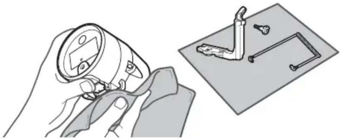
The flash unit uses an O-ring to form a watertight seal. Improper handling of the O-ring can produce leaks. Check the condition of the O-ring as described below whenever the unit has been used under water.
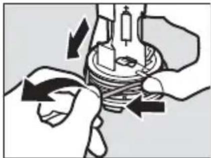
1 Remove the O-ring.
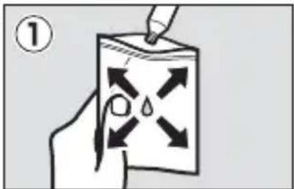
Lightly stretch the O-ring by sliding your fingers along either side and remove it from the unit. Do not apply excessive force or use your fingernails, metal objects, or edged or pointed tools.
natural_image
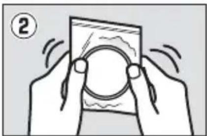
Illustration of hands performing a mechanical operation with arrows indicating direction (no text or symbols)2 Wash the O-ring.
Wash the O-ring in fresh water and dry thoroughly. Do not use benzene, thinner, alcohol, soap, neutral detergents, or other cleaning products, as these could damage or weaken the O-ring.
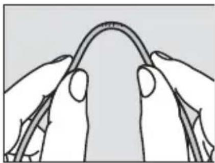
3 Inspect the O-ring.
Remove any foreign matter with a soft, dry cloth, taking care not to leave tissue or threads on the O-ring. Gently bend the O-ring to check for cracking or other damage.
natural_image
Line drawing of two hands holding a curved object, possibly a tool or device (no text or symbols present)4 Inspect the O-ring guide.
Use a blower or cotton swab to remove any foreign objects from the O-ring guide. Be sure to remove any threads left behind by the swab.
natural_image
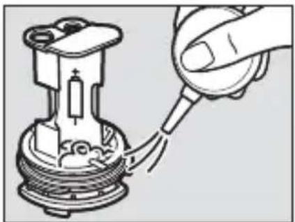
Diagram of a hand inserting a plug into a mechanical component (no text or symbols)5 Grease the O-ring.
Squeeze about fi ve millimeters (a quarter of an inch) of silicon grease into a plastic bag and use your fi n-gers to spread the grease throughout the bag (①). Next, insert the O-ring and massage the bag to coat the ring (②).
natural_image
Illustration of two hands holding a smartphone with a circular lens, no text or symbols present6 Re-insert the O-ring.
After making sure that O-ring and guide are free of foreign objects, place the O-ring so that it runs evenly at the same level all the way round the O-ring guide, without undue stretching and without protruding from the guide.
natural_image
Mechanical component diagram showing a base with mounting holes and a central housing (no text or symbols)

O-Rings
The O-ring requires periodic replacement. Replace the O-ring immediately if it is damaged, cracked, warped, or has lost its elasticity. O-rings should be replaced at least once a year even if the unit has not been used; use only O-rings designated for use in this unit. O-rings must be greased before use and whenever the surface appears dry; failure to observe this precaution could result in the O-ring cracking and water entering the unit.

SiliconGrease
Coating the O-ring with the supplied silicon grease prevents wear and ensures that the holder rotates smoothly. Use only the supplied silicon grease or optional WP-G1000 silicon grease; failure to observe this precaution could result in O-ring becoming stretched or otherwise deformed. Replacement O-rings and silicon grease are available for separate purchase. Do not use grease in excessive amounts or apply using paper or cloth, as this may cause dust or fibers to adhere to the O-ring, making the unit vulnerable to leaks.
Observe the following precautions when cleaning and storing the unit after underwater use.
- Before inserting or removing the battery holder, fi nd a shaded location free from spray, wind, dust, and sand, and be sure your hands are dry. Before removing the holder, wipe the unit with a soft, dry cloth to remove any water. Water dropping from the battery holder into the unit could result in condensation or other damage.
- Benzene, thinner, alcohol, soap, neutral detergents, and other cleaning products may deform the unit, making it vulnerable to leaks.
- After washing the unit in fresh water, remove any visible water with a soft, dry cloth and leave the unit in a shady, well-ventilated area to dry. Do not leave it in direct sunlight or dry it with hair dryers or other powered devices. Failure to observe this precaution could damage the unit, resulting in leaks.
- If the unit will not be used for an extended period, remove the batteries and store it in a cool, well-ventilated area. To protect the unit from mold, mildew, rust, or corrosion, avoid locations that are exposed to direct sunlight, extreme temperatures, or high humidity and do not store the unit with naphtha or camphor mothballs or in laboratories or other locations where volatile chemicals are used.
- Inspect the O-ring before and after use and before placing the unit in storage. Nikon recommends that the O-ring be replaced before it shows signs of wear.
- Although the need for servicing will vary with storage conditions and how often the unit is used, it is recommended that it be serviced about once every two years by Nikon-authorized service personnel, starting from the date of purchase. A fee is charged for this service.
- Take the unit from storage about once a month, insert the batteries, fi re it, and test the controls. Before returning the unit to storage, confi rm that the fl ash-ready lamp lights red, and then turn the fl ash off and remove the batteries.
Troubleshooting
If the flash unit fails to function as expected, check the list of common problems below before consulting your retailer or Nikon representative.
The flash does not charge (the flash-ready lamp does not light red):
- Confirm that the batteries are not exhausted and are inserted in the correct orientation and that the battery holder is fully inserted.
- The unit will shut down temporarily to protect the internal circuits after it has fi red several times in quick succession or when the ambient temperature is high. Turn the unit off and let it cool for a few minutes; if the ambient temperature is high, move it to a cool location. Note that if the flash has been fired at full power more than 20 times in succession, it will automatically shut down for at least 20 seconds to protect fl ash and the flash-ready lamp will turn off; in this case, leave the flash off for at least 10 minutes before resuming use.
The flash does not fire:
- Confirm that the fi ber-optic cable is securely connected.
- Confirm that the camera's built-in flash is set to fire with every shot.
- Check the camera shooting and flash mode settings.
The flash-ready lamp does not light green after the flash fires in TTL mode:
- If the flash-ready lamp is lit blue, keep the targeting lamp button pressed until the lamp lights red (about three seconds) to show that flash-compensation support is enabled.
- Adjust the distance to the subject and try again.
The subject is over- or under-exposed in pictures taken in TTL flash control mode:
- Confirm that the fi ber-optic cable is securely connected.
- Depending on camera settings and shooting conditions, adjustments to flash level using the flash-level dial may not have the desired effect.
The subject is underexposed in pictures taken in manual flash control mode: The flash control mode selected with the flash mode dial does not match that selected in the camera shooting menu.
The flash turns off automatically: The flash will turn off automatically if it has not been fired for a set period. Turn the flash off and then on again.
Specifications
| Type Underwater speed | dlight with TTL fl ash control |
| Guide number (air; ISO 100, m/ft) | 28/92 at full power, 20/66 with underwater wide-fl ash adapter |
| Angle of illumination 80° | horizontal and vertical; 110° horizontal and vertical with underwater wide-fl ash adapter |
| Effective flash range | 0.3 m to 4 m (1.0 ft to 13.1 ft); varies with ISO sensitivity and aperture |
| Device on/off Mode dial | used to turn unit on and off |
| Controls Mode dial, targeting lamp button (on/off), fl ash-level dial | |
| Color temperature (air) | 5600K at full power |
| Power source Four AA alkaline or four AA NiMH batteries | |
| Flash-ready lamp | Lights red: Flash is charged and ready for use (does not apply if fl ash-compensation support is disabled)Lights green for 2 s: Flash fi red in TTL modeLights blue: Flash-compensation support disabledBlinks red and green: Batteries exhaustedBlinks red or blue: Temperature warning |
| Battery endurance | Alkaline batteries: Approximately 180 usesNiMH batteries: Approximately 220 uses |
| Recycling time | Alkaline batteries: Approximately 2.5 sNiMH batteries: Approximately 1.8 s |
| Operating temperature (in water) | 0 °C–40 °C (+32 °F–+104 °F) |
| Materials | Polycarbonate and ABS resins |
| Maximum depth | 100 m (328 ft) |
| Dimensions(W × H × D) | Approximately 87 × 133 × 140 mm (3.4 × 5.2 × 5.5 in.), excluding projections |
| Weight Approximately | 627 g (1 lb 6.1 oz), excluding batteries |
| Underwater weight Approximately | 90 g (3.2 oz), including batteries |
Improvements to this product may result in unannounced changes to specifications and external appearance. Nikon will not be held liable for damages that may result from any errors this manual may contain. All figures are for a unit with fresh batteries. Unless otherwise stated, all measurements are performed in conformity with Camera and Imaging Products Association (CIPA) guidelines.
Accessories Available for Separate Purchase
Nikon offers the following options and replacement items:
• Underwater Bracket SK-N10A
• Underwater Fiber-Optic Cable Adapter SR-N10A
• Underwater Fiber-Optic Cable SC-N10A
• Underwater Wide-Flash Adapter SW-N10A
- O-Ring WP-O3000
• Silicon Grease WP-G1000
natural_image
Symbol of a trash bin crossed with no text or labelsnatural_image
Line drawing of a cylindrical device with a rectangular component and mounting base (no text or symbols)natural_image
Technical line drawing of a mechanical component with no visible text or symbolsnatural_image
Simple line drawing of a cotton tube with a cap (no text or symbols)Silikonfett WP-G1000
natural_image
Technical line drawing of a mechanical bracket or support structure (no text or symbols)natural_image
Simple line drawing of a mechanical linkage or bracket (no text or symbols)natural_image
Line drawing of a handheld electronic device (no text or symbols)natural_image
Cross-sectional diagram of an internal combustion engine cylinder (O-Ring) showing piston, crankshaft, and housing components without any text labels or symbols.natural_image
Line drawing of a mechanical device with gear and control knob (no text or symbols)natural_image
Technical line drawing of a mechanical device with a rotating shaft and housing (no text or symbols)natural_image
Diagram of a camera assembly with a base mount and adjustment lever (no text or symbols)natural_image
Diagram of a digital camera module with buttons and a base panel, showing no text or symbols.natural_image
Line drawing of a DSLR camera with a right-angle lever and adjustment arrow (no text or symbols)natural_image
Technical line drawing of a camera with directional arrows indicating motion or force (no text or symbols)natural_image
Technical line drawing of a mechanical assembly with no visible text or symbolsnatural_image
Mechanical assembly diagram showing a wrench inserted into a component with a black arrow indicating the direction (no text or symbols present)natural_image
Mechanical assembly diagram showing a valve mechanism with a connector and directional arrow (no text or labels)
natural_image
Line drawing of a DSLR camera with attached optical lens (no text or symbols)■ Kamera Nikon 1 AW1
natural_image
Line drawing of a DSLR camera with lens and external handle (no text or symbols)natural_image
Line drawing of a digital camera with an attached base and a screen, showing no text or symbols.natural_image
Diagram of a camera assembly with a mounted lens and base mount (no text or symbols)natural_image
Diagram of a digital camera module with an open case and directional arrows indicating assembly or movement (no text or symbols present)natural_image
Technical line drawing of a camera module with no visible text or symbolsnatural_image
Technical line drawing of a camera frame with directional arrows indicating motion (no text or symbols)natural_image
Technical line drawing of a mechanical assembly with no visible text or symbolsnatural_image
Mechanical assembly diagram showing a tool interacting with a component (no text or symbols visible)natural_image
Technical line drawing of a mounted optical instrument with lens and housing (no text or symbols)natural_image
Illustration of hands operating a digital camera with a mechanical device (no text or symbols visible)

natural_image
Technical line drawings of four different camera components (no text or symbols)natural_image
Illustration of a hand holding a magnifying glass over a workbench with tools and components (no text or symbols)natural_image
Illustration of a mechanical assembly with tools and components (no text or symbols)natural_image
Technical illustration of a mechanical device with a cylindrical component and a separate housing (no text or symbols)De
Wartung
natural_image
Diagram of hands performing a mechanical operation with arrows indicating direction (no text or symbols present)natural_image
Line drawing of two hands holding a curved object, possibly a tool or wire (no text or symbols)natural_image
Diagram of a mechanical component being inserted into a housing, showing internal structure and part assembly (no text or labels)natural_image
Illustration of two hands holding a smartphone with a circular lens and motion lines (no text or symbols)De
natural_image
Mechanical component diagram showing a base with mounting holes and internal components (no text or symbols)
0-Ringe
natural_image
Symbol of a trash bin crossed out by two diagonal lines (no text or numbers present)natural_image
Line drawing of a cylindrical device with a rectangular component and mounting base (no text or symbols)natural_image
Simple line drawing of a mechanical component with no text or symbolsnatural_image
Simple line drawing of a tube with a cap (no text or symbols)natural_image
Technical line drawing of a mechanical bracket or support structure (no text or symbols)natural_image
Simple line drawing of a mechanical clamp or bracket (no text or symbols)natural_image
Simple line drawing of a handheld device with a handle and top panel (no text or symbols)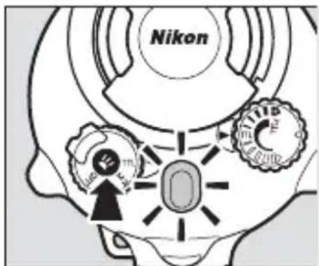
Fr
natural_image
Technical line drawing of a mechanical piston assembly (no text or symbols)Joint torique
Insertion des accumulateurs/piles
natural_image
Technical line drawing of a mechanical device with internal components and a directional arrow indicating motion (no text or symbols)natural_image
Diagram of a DSLR camera with a base mount and adjustment lever (no text or symbols)natural_image
Diagram of a digital camera module with buttons and a base panel, showing no text or symbols.natural_image
Line drawing of a DSLR camera with a right-angle mechanism (no text or symbols)natural_image
Technical line drawing of a camera with directional arrows indicating motion or force (no text or symbols)natural_image
Technical line drawing of a mechanical assembly with no visible text or symbolsnatural_image
Mechanical assembly diagram showing a wrench inserted into a component with a black arrow indicating the direction (no text or symbols present)natural_image
Mechanical assembly diagram showing a valve mechanism with a connector and directional arrow (no text or labels)
natural_image
Line drawing of a DSLR camera with attached optical lens (no text or symbols)■ Appareils photo Nikon 1 AW1
natural_image
Line drawing of a DSLR camera with lens and external handle (no text or symbols)natural_image
Line drawing of a digital camera with an attached base and a screen, showing no text or symbols.3 Fixez le fl ash.
natural_image
Diagram of a camera assembly with a mounted lens and base mount (no text or symbols)natural_image
Diagram of a digital camera module with an open case and directional arrows indicating motion (no text or symbols present)natural_image
Technical line drawing of a camera module with no visible text or symbolsnatural_image
Technical line drawing of a camera frame with adjustment knobs and lever mechanism (no text or symbols)natural_image
Technical line drawing of a mechanical assembly with no visible text or symbolsnatural_image
Mechanical assembly diagram showing a tool interacting with a component, no visible text or symbolsnatural_image
Technical line drawing of a mounted optical or imaging device with a cylindrical lens and attached housing (no text or symbols)natural_image
Technical line drawings of two camera modules with lenses and wiring (no text or symbols)natural_image
Illustration of hands operating a digital camera with a mechanical device (no text or symbols visible)

Précautions
natural_image
Black-and-white photo of a smiling child sitting on a chair, with no visible text or symbols in the main image area.
natural_image
Black-and-white photo of a smiling child sitting in a chair outdoors, with no visible text or symbols on the image itself.
■ Fixation du diff useur
natural_image
Technical illustration of a mechanical component with an inset close-up showing internal components (no text or symbols)Partie saillante
natural_image
Technical line drawings of three mechanical components: a camera, a lens, and a spring-loaded bracket (no text or symbols)2 Immergez le fl ash.
natural_image
Illustration of a hand using a magnifying glass to adjust a mechanical component, with no visible text or symbols.natural_image
Illustration of a mechanical clamp and tool on a workbench (no text or symbols)natural_image
Technical illustration of a mechanical device with a cylindrical component and a separate motor housing (no text or symbols)Fr
Entretien
natural_image
Diagram of hands performing a mechanical operation with arrows indicating motion (no text or symbols)2 Rincez le joint torique.
natural_image
Line drawing of two hands holding a curved object, possibly a tool or cable (no text or symbols)natural_image
Diagram of a mechanical component being inserted into a housing, showing internal structure and part assembly (no text or labels)natural_image
Illustration of two hands holding a smartphone with a circular lens, no text or symbols presentnatural_image
Mechanical component diagram showing a base with mounting holes and internal components (no text or symbols)Joints toriques
natural_image
Symbol of a trash bin crossed out by two crossed lines (no text or numbers present)natural_image
Line drawing of a cylindrical mechanical device with mounting feet and a central display (no text or symbols)natural_image
Simple line drawing of a circular mechanical component with no text or symbols□Difusor de flash submarino SW-N10A
natural_image
Simple line drawing of a tube with a cap (no text or symbols)□ Grasa de silicona WP-G1000
natural_image
Technical line drawing of a mechanical bracket or support structure (no text or symbols)□Empuñadura submarina SK-N10A
natural_image
Simple line drawing of a mechanical clamp or bracket (no text or symbols)natural_image
Simple line drawing of a mechanical clamp or bracket (no text or symbols)natural_image
Technical line drawing of a mechanical piston assembly (no text or symbols)Junta tórica
natural_image
Technical line drawing of a mechanical device with internal components and a directional arrow indicating motion (no text or symbols)natural_image
Diagram of a camera assembly with a base mount and adjustment lever (no text or symbols)3 Coloque la carcasa subacuática.
natural_image
Diagram of a digital camera module with buttons and a base panel, showing no text or symbols.natural_image
Line drawing of a DSLR camera with attached lever and adjustment knob (no text or symbols)natural_image
Technical line drawing of a camera with directional arrows indicating motion or force (no text or symbols)natural_image
Technical line drawing of a mechanical assembly with no visible text or symbolsnatural_image
Mechanical assembly diagram showing a wrench tool interacting with a mechanical component (no text or symbols visible)natural_image
Mechanical assembly diagram showing a valve mechanism with a connector (no text or labels)
natural_image
Line drawing of a DSLR camera with attached optical lens (no text or symbols)■ Cámaras Nikon 1 AW1
natural_image
Line drawing of a DSLR camera with lens and external handle (no text or symbols)natural_image
Line drawing of a digital camera with an attached base and a scroll wheel (no text or symbols)natural_image
Diagram of a camera assembly with a mounted lens and base mount (no text or symbols)natural_image
Diagram of a digital camera module with an open case and directional arrows indicating motion (no text or symbols present)natural_image
Technical line drawing of a camera module with no visible text or symbolsnatural_image
Technical line drawing of a mechanical device with clamping mechanism (no text or symbols)natural_image
Technical line drawing of a mechanical assembly with no visible text or symbolsnatural_image
Mechanical assembly diagram showing a tool interacting with a component (no text or symbols visible)10 Conecte el cable al adaptador.
natural_image
Technical line drawing of a mounted optical or imaging device with a cylindrical lens and attached housing (no text or symbols)natural_image
Technical line drawings of two camera modules with lenses and connectors (no text or symbols)natural_image
Illustration of a hand holding a camera with a mounted device, no text or symbols presentEs

Precauciones
3 Tome imágenes.
Nivel del flash
natural_image
Technical illustration of a mechanical component with an inset close-up showing a detail (no text or symbols)Lengüeta
Después del uso
natural_image
Technical line drawings of four different camera components (no text or symbols)natural_image
Illustration of a hand holding a magnifying glass over a surface with tools, alongside a close-up of a mechanical component (no text or symbols present)natural_image
Illustration of a mechanical clamp and tool assembly (no text or symbols)natural_image
Technical illustration of a mechanical device with a cylindrical component and a separate housing (no text or symbols)Es
Mantenimiento
natural_image
Diagram of hands performing a mechanical operation with arrows indicating motion (no text or symbols)natural_image
Illustration of two hands holding a curved, knotted object (no text or symbols)natural_image
Diagram of a hand inserting a plug into a mechanical component (no text or symbols visible)natural_image
Mechanical component diagram showing a piston-like assembly with mounting holes and internal components (no text or symbols)
Juntas tóricas
natural_image
Symbol of a trash bin crossed out by two diagonal lines (no text or numbers present)
natural_image
Line drawing of a cylindrical device with a central screen and mounting bracket (no text or symbols)natural_image
Technical line drawing of a mechanical component with no visible text or symbols□ Pannello rifl ettente esterno per fl ash subacqueo SW-N10A

natural_image
Simple line drawing of a tube with a cap (no text or symbols)Grasso siliconico WP-G1000
lt
Accessoririchiesti
natural_image
Technical line drawing of a mechanical bracket or support structure (no text or symbols)natural_image
Simple line drawing of a mechanical clamp or bracket (no text or symbols)□Cavo in fi bra ottica subacqueo SC-N10A
natural_image
Simple line drawing of a mechanical clamp or bracket (no text or symbols)The Ground Truth image displays a single, solid horizontal line. According to Rule 2 (UNDERSCORE & LINE RULES), this is a stylistic or background line, not a placeholder underscore. Therefore, the OCR result must ignore it and output nothing or only meaningful text. The provided OCR content is "____", which consists of four underscores. This is an incorrect interpretation of the line as a placeholder, violating the rule that stylistic lines must be ignored. The OCR has hallucinated placeholder underscores where none exist in the GT. Hence, the OCR result is inconsistent with the Ground Truth.
natural_image
Close-up of a mechanical device's gear and dial (no text or symbols visible)natural_image
Technical line drawing of a mechanical device with internal components and a directional arrow indicating motion (no text or symbols)4 Inserire le batterie.
natural_image
Diagram of a camera assembly with a base mount and adjustment lever (no text or symbols)natural_image
Diagram of a digital camera module with buttons and a base panel, showing no text or symbols.natural_image
Line drawing of a DSLR camera with lever and base mount (no text or symbols)natural_image
Technical line drawing of a camera with directional arrows indicating motion or force (no text or symbols)natural_image
Technical line drawing of a mechanical assembly with no visible text or symbolsIt
natural_image
Mechanical assembly diagram showing a wrench tool interacting with a mechanical component (no text or symbols visible)natural_image
Mechanical assembly diagram showing a valve mechanism with a tool inserted (no text or labels)
natural_image
Line drawing of a DSLR camera with attached optical lens (no text or symbols)■ Fotocamere Nikon 1 AW1
natural_image
Line drawing of a DSLR camera with lens and external handle (no text or symbols)natural_image
Line drawing of a digital camera with an attached base and a scroll wheel (no text or symbols)natural_image
Diagram of a camera assembly with a mounted lens and base mount (no text or symbols)natural_image
Diagram of a digital camera module with an open case and directional arrows indicating motion (no text or symbols present)natural_image
Technical line drawing of a camera module with no visible text or symbolsnatural_image
Technical line drawing of a mechanical device with arrows indicating motion or force direction (no text or symbols)natural_image
Technical line drawing of a mechanical assembly with no visible text or symbolsnatural_image
Mechanical assembly diagram showing a tool interacting with a component (no text or symbols visible)natural_image
Technical line drawing of a mounted optical instrument with lens and frame (no text or symbols)natural_image
Technical line drawings of two camera modules with lenses and connectors (no text or symbols)natural_image
Illustration of a hand holding a camera with a mounted device, no text or symbols present
Precauzioni
natural_image
Black-and-white photo of a smiling child sitting on a chair, with no visible text or symbols in the main image area.

natural_image
Black-and-white photo of a smiling child sitting in a chair, with no visible text or symbols on the main subject.
3 Scattare le foto.
Livello flash
natural_image
Technical line drawings of four different mechanical components: a camera, a lens, a spring-loaded bracket, and a separate bracket (no text or symbols present)natural_image
Illustration of a hand holding a magnifying glass over a small electronic component, with no visible text or symbols.natural_image
Illustration of a mechanical clamp and tool on a workbench (no text or symbols)natural_image
Technical illustration of a mechanical device with a cylindrical component and a separate motor housing (no text or symbols)Manutenzione
natural_image
Diagram of hands performing a mechanical operation with arrows indicating motion (no text or symbols)2 Lavare l'O-ring.
natural_image
Illustration of two hands holding a curved, knotted object (no text or symbols)natural_image
Diagram of a mechanical component being inserted into a housing, showing internal structure and part assembly (no text or labels)5 Ingrassare l'O-ring.
natural_image
Illustration of two hands holding a smartphone with motion lines indicating sound or vibration (no text or symbols)6 Reinserire l'O-ring.
natural_image
Mechanical component diagram showing a base with flanged ends and a central housing (no text or symbols)
Gli 0-ring
natural_image
Line drawing of a cylindrical device with a rectangular component and mounting base (no text or symbols)□SB-N10水下闪光灯
(已装好WP-O3000 O型环;
使用之前,请按照第34页
中所述确认O型环未损坏)
□宽面板闪光灯适配器带
□使用说明书(本说明书)
□保修卡
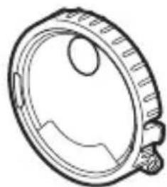
natural_image
Technical line drawing of a mechanical component with no visible text or symbols□SW-N10A水下宽面板闪光灯适配器
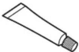
natural_image
Simple line drawing of a tube with a cap (no text or symbols)□WP-G1000硅润滑脂
Sc
必要配件
natural_image
Technical line drawing of a mechanical bracket or support structure (no text or symbols)□SK-N10A水下托架
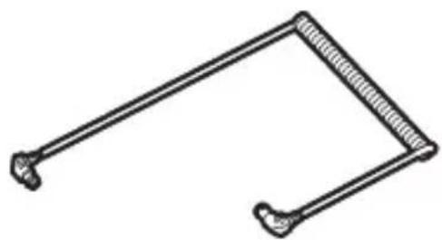
natural_image
Simple line drawing of a mechanical linkage or tool (no text or symbols)□SC-N10A水下光纤连接线
natural_image
Line drawing of a handheld electronic device (no text or symbols)□SR-N10A水下光纤连接线适配器
4 感应器盖……12、16、32
5 光纤接口……12、17
The Ground Truth image displays a single, solid horizontal line. According to Rule 2 (UNDERSCORE & LINE RULES), this is a stylistic or background line, not a placeholder underscore. Therefore, the OCR result must ignore it and output nothing or only meaningful text. The provided OCR content is "____", which consists of four underscores. This is an incorrect interpretation of the line as a placeholder, violating the rule that stylistic lines must be ignored. The OCR has hallucinated placeholder underscores where none exist in the GT. Hence, the result is inconsistent with the Ground Truth.
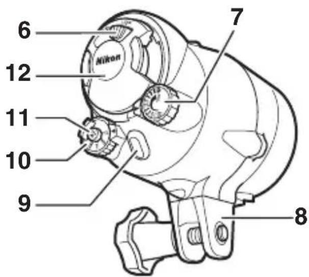
自动关机
natural_image
Cross-sectional diagram of a piston assembly with internal components (no text or labels)O型环
插入电池
natural_image
Technical line drawing of a mechanical device with a rotating shaft and housing (no text or symbols)4 插入电池。
如图示方向插入电池。
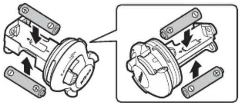
Sc
5 重新插入电池座。
6 锁定电池磨。
2 将防水罩置于托架上。
natural_image
Diagram of a camera assembly with a base mount and adjustment arrow (no text or symbols)3 调整防水罩的位置。
滑动防水罩直至其接触到支板固定导槽。
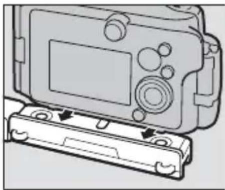
natural_image
Diagram of a digital camera module with buttons and a base case, showing no text or symbols.4 拧紧锁定齿圈。
将锁定齿圈完全拧紧。
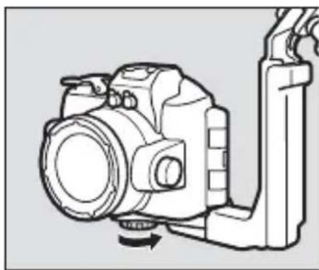
natural_image
Line drawing of a DSLR camera with lever and base mount (no text or symbols)5 将连接线穿过手柄。
natural_image
Technical line drawing of a camera with directional arrows indicating motion or force (no text or symbols)6 打开感应器盖。
打开闪光灯组件感应器盖。
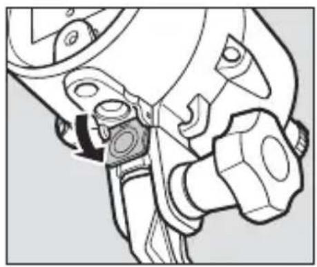
natural_image
Technical line drawing of a mechanical assembly with no visible text or symbols7 将连接线连接至闪光灯组件。
natural_image
Mechanical assembly diagram showing a wrench and nut being inserted into a tool (no text or symbols present)8 将连接线连接至防水罩。
将底部连接器插入防水罩上的光纤接口中。
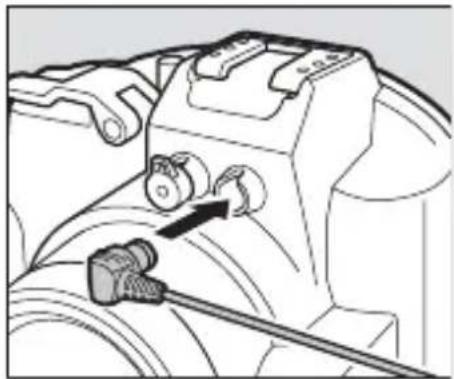
natural_image
Mechanical assembly diagram showing a valve mechanism with a black arrow indicating direction (no text or symbols present)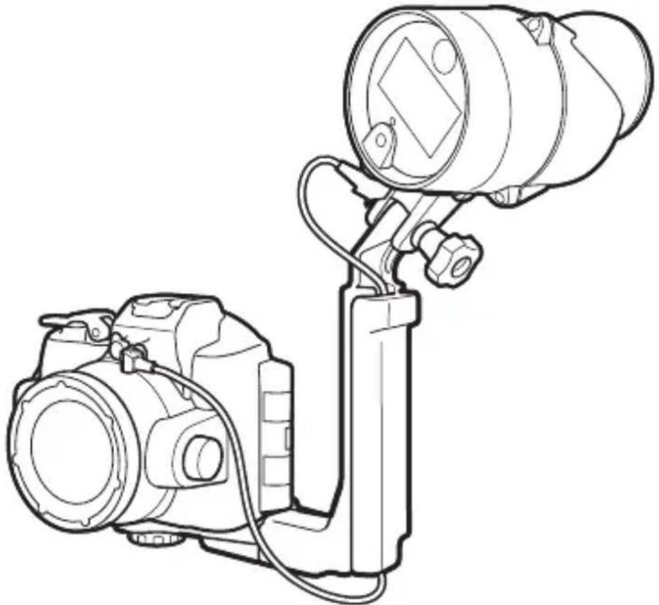
natural_image
Line drawing of a DSLR camera with attached optical lens (no text or symbols)■ Nikon 1 AW1 照相机
natural_image
Line drawing of a DSLR camera with lens and handle (no text or symbols)2 安装光纤连接线适配器。
natural_image
Line drawing of a digital camera with an attached base, showing no text or symbols3 安装闪光灯组件。
使用固定螺栓将本组件安装至手柄。
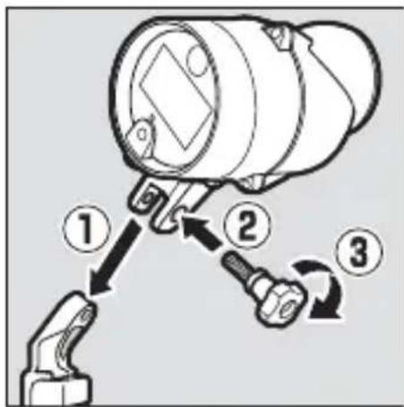
4 将照相机/适配器组合体置于托架上。
natural_image
Diagram of a camera assembly with a mounted lens and base mount (no text or symbols)5 调整照相机/适配器组合体的位置。
滑动组合体直至其接触到支板固定导槽。
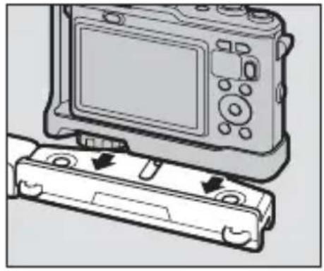
natural_image
Diagram of a digital camera module with a cable attachment, showing no text or symbols6 拧紧防水罩/适配器锁定齿圈。
将锁定齿圈完全拧紧。
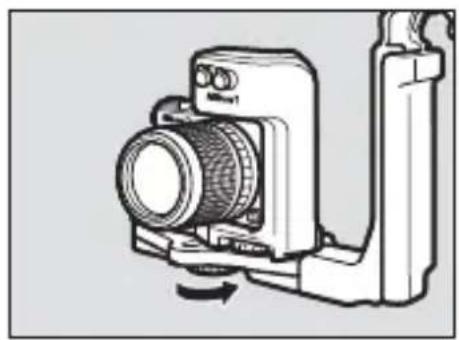
natural_image
Technical line drawing of a camera module with no visible text or symbols7 将连接线穿过手柄。
natural_image
Technical line drawing of a mechanical device with directional arrows indicating motion or force (no text or symbols)8 打开感应器盖。
打开闪光灯组件感应器盖。
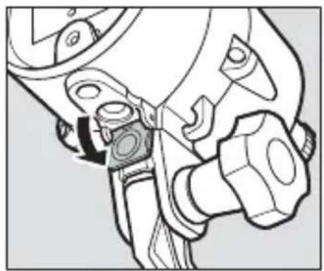
natural_image
Technical line drawing of a mechanical assembly with no visible text or symbols9 将连接线连接至闪光灯组件。
natural_image
Mechanical assembly diagram showing a tool interacting with a component (no text or symbols visible)10 将连接线连接至适配器。
natural_image
Technical line drawing of a camera setup with lens and mounted device (no text or symbols)natural_image
Technical line drawings of two camera modules with lenses and sensors (no text or symbols)natural_image
Illustration of hands operating a digital camera with a mechanical device (no text or symbols visible)请与尼康授权的
Sc
√注意事项
natural_image
Technical line drawings of four mechanical components: a camera, a lens, a spring-loaded bracket, and a separate clamp (no text or symbols present)natural_image
Illustration of a hand using a magnifying glass to measure a tool, with a close-up of the tool on a flat surface (no text or symbols present)5 在阴凉处晾干组件。
将本组件置于阴凉、通风良好的地方晾干。
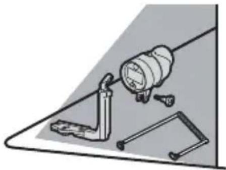
natural_image
Illustration of a mechanical clamp and lever assembly (no text or symbols)6 清洁电池座。
natural_image
Technical illustration of a mechanical device with a cylindrical component and a separate motor housing (no text or symbols)Sc
保养
natural_image
Illustration of hands performing a mechanical operation with arrows indicating direction (no text or symbols)2 清洗O型环。
natural_image
Line drawing of two hands holding a thin, curved object (no text or symbols)4 检查O型环导槽。
natural_image
Illustration of a hand turning a valve into a mechanical component (no text or symbols)5 润滑O型环。
natural_image
Illustration of two hands holding a smartphone with a circular screen and motion lines (no text or symbols)6 重新放入O型环。
natural_image
Technical illustration of a mechanical component with no visible text or symbolsVO型环
natural_image
Line drawing of a cylindrical device with a rectangular lens and attached ports, labeled '光' at the bottom (no other text or symbols)natural_image
Technical line drawing of a mechanical component with no visible text or symbolsnatural_image
Simple line drawing of a tube with a cap (no text or symbols)□WP-G1000矽潤滑油
必要配件
natural_image
Technical line drawing of a mechanical bracket or support structure (no text or symbols)□SK-N10A 水底托架

natural_image
Simple line drawing of a mechanical linkage or bracket (no text or symbols)□SC-N10A 水底光纜和
natural_image
Line drawing of a handheld electronic device (no text or symbols)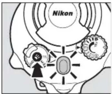
Tc
光 閃燈就緒指示燈 光
查閃燈狀態。 看
natural_image
Cross-sectional diagram of a mechanical piston assembly (no text or labels)O型環
插入電池
Tc
2 解除電池座的鎖定。
natural_image
Technical line drawing of a mechanical device with a rotating shaft and housing (no text or symbols)4 插入電池。
如圖示方向插入電池。
5 重新插入電池座。
6 鎖定電池座。
2 將防水罩置於托架上。
natural_image
Diagram of a camera assembly with a base mount and adjustment lever (no text or symbols)3 調整防水罩的位置。
滑動防水罩直至其接觸到支板固定導槽。
natural_image
Diagram of a digital camera module with a base case and control panel (no text or symbols)4 據緊鎖定螺絲。
將鎖定螺絲完全擰緊。
natural_image
Line drawing of a DSLR camera with lever and base mount (no text or symbols)5 將光纜穿過手柄。
natural_image
Technical line drawing of a camera with directional arrows indicating movement or force (no text or symbols)6 打開感應器蓋。
打開閃燈元件感應器蓋。
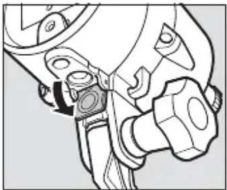
natural_image
Technical line drawing of a mechanical assembly with no visible text or symbols光
7 將光纜連接至閃燈元件。
natural_image
Mechanical assembly diagram showing a wrench inserted into a component, with an arrow indicating the direction of movement (no text or symbols present)8 將光纜連接至防水罩。
將底部連接器插入防水罩上的纖連接器中。
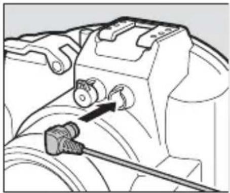
natural_image
Mechanical assembly diagram showing a valve mechanism with a connector and cable (no text or symbols)
natural_image
Line drawing of a DSLR camera with mounted lens and external components (no text or symbols)Tc
■ Nikon 1 AW1 相機
和光
natural_image
Line drawing of a DSLR camera with lens and external handle (no text or symbols)光
2 安裝纜配接器。
natural_image
Line drawing of a digital camera with an attached base and a screen, showing no text or symbols.光
3 安装閃燈元件。
使用固定螺栓將本元件安裝至手柄。
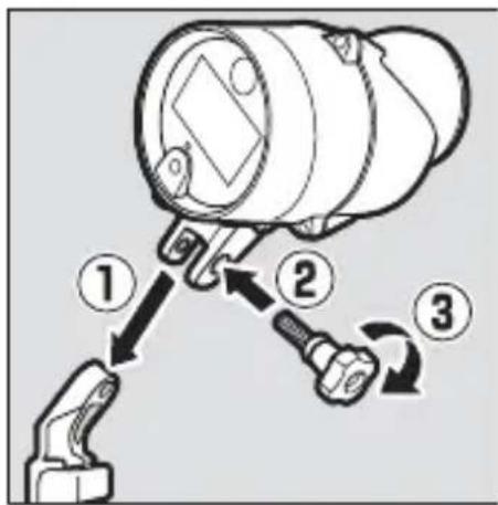
natural_image
Diagram of a camera assembly with a sensor mounted on a base, showing mechanical components and a directional arrow (no text or symbols present)5 調整相機 / 配接器組合體的位置。
滑動組合體直至其接觸到支板固定導槽。
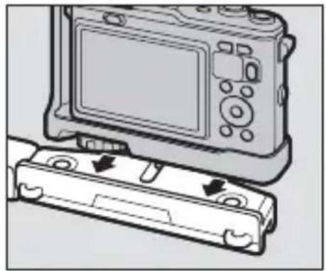
natural_image
Diagram of a digital camera with an attached case showing internal components (no text or symbols)6 據緊防水罩 / 配接器鎖定螺絲。
將鎖定螺絲完全擰緊。
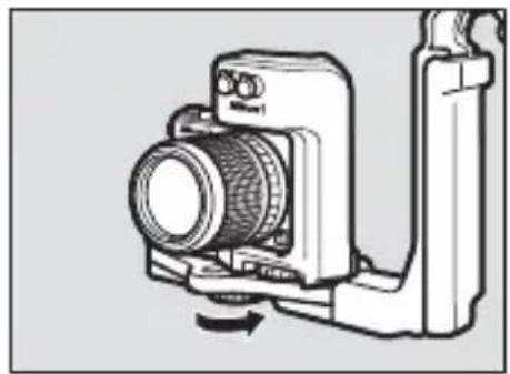
natural_image
Diagram of a camera with lens and adjustment knob, no text or symbols present7 將光纜穿過手柄。
natural_image
Technical line drawing of a camera with directional arrows indicating motion or force (no text or symbols)8 打開感應器蓋。
打開閃燈元件感應器蓋。
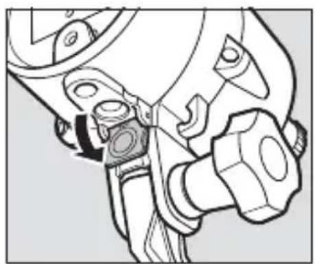
natural_image
Technical line drawing of a mechanical assembly with no visible text or symbols9 將光纜連接至閃燈元件。
natural_image
Mechanical assembly diagram showing a tool interacting with a mechanical component (no text or symbols visible)10 將光纜連接至配接器。
natural_image
Technical line drawing of a camera setup with lens, lens, and mounted device (no text or symbols)natural_image
Line drawing of a camera with an optical lens mounted on a stand (no text or symbols)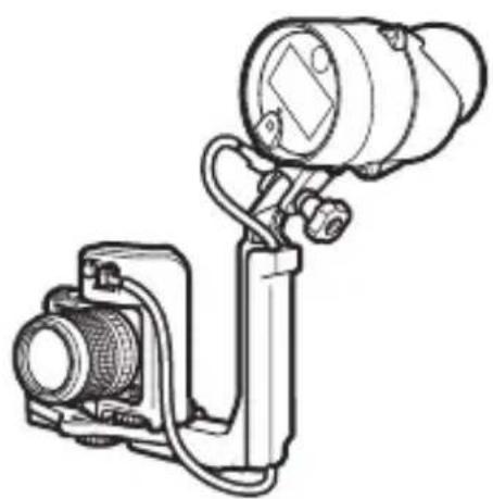
natural_image
Technical line drawing of a mechanical device with a mounted optical lens and housing (no text or symbols)光升
natural_image
Illustration of hands operating a camera with a mounted device (no text or symbols visible)Tc
√ 注意事項

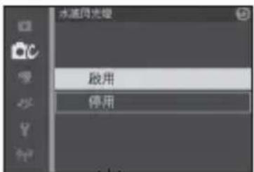

3 拍攝照片。光
閃等級
光 光
natural_image
Technical line drawings of four different camera components: a flat bracket, a mounted lens, a flexible spring, and a connector (no text or symbols present)Tc
2 將元件浸入水中。
natural_image
Illustration of a hand holding a magnifying glass over a small object, with no visible text or symbols.5 在陰涼處晾乾元件。
將本元件置於陰涼、通風良好的地方晾乾。
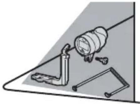
natural_image
Illustration of a mechanical assembly with a cylindrical component and tools (no text or symbols)6 清潔電池座。
natural_image
Technical line drawing of a mechanical device with a cylindrical component and a separate motor housing (no text or symbols)Tc
保養
光
natural_image
Illustration of hands performing a mechanical operation with arrows indicating motion (no text or symbols)2 清洗O型環。
natural_image
Line drawing of two hands holding a curved object, possibly a wire or fiber (no text or symbols)4 檢查 0 型環導槽。
natural_image
Diagram of a hand turning a valve into a mechanical component (no text or symbols)5 潤滑 O 型環。
natural_image
Illustration of two hands holding a smartphone with a circular lens and motion lines (no text or symbols)6 重新放入 O 型環。
natural_image
Mechanical component diagram showing a base with mounting holes and internal components (no text or symbols)Tc
VO型環
natural_image
Line drawing of a cylindrical mechanical device with mounting flanges and a central screen (no text or symbols)natural_image
Line drawing of a mechanical component with no visible text or symbolsnatural_image
Simple line drawing of a tube with a textured cap (no text or symbols)□WP-G1000 실리콘 그리스
필수 액세서리
natural_image
Technical line drawing of a mechanical bracket or support structure (no text or symbols)□SK-N10A 수중 브라켓
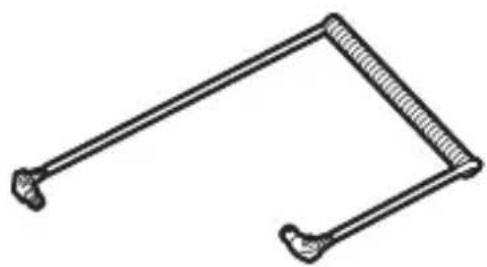
natural_image
Simple line drawing of a mechanical clamp or bracket (no text or symbols)□SC-N10A 수중 광섬유 케이블
natural_image
Simple line drawing of a handheld device with no text or symbolsnatural_image
Technical line drawing of a mechanical device with internal components and a directional arrow indicating rotation (no text or symbols)4 배터리를 삽입합니다.
5 홀더를 교체합니다.
6 홀더를 잠Gb니다.
natural_image
Diagram of a DSLR camera with a base mount and adjustment knob, showing mechanical assembly (no text or symbols)natural_image
Diagram of a digital camera module with a cable attachment (no text or symbols)4 잠금 나사를 조여줍니다.
잠금 나사를 완전히 조여줍니다.
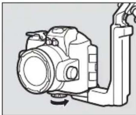
natural_image
Line drawing of a DSLR camera with a lever and scroll attachment (no text or symbols)natural_image
Technical line drawing of a mechanical assembly with no visible text or symbols7 케이블과 플래시를 연결합니다.
natural_image
Mechanical assembly diagram showing a tool interacting with a mechanical component (no text or symbols visible)Kr
natural_image
Mechanical assembly diagram showing a valve mechanism with a tool inserted (no text or labels)
natural_image
Line drawing of a DSLR camera with mounted lens and attached stand (no text or symbols)natural_image
Line drawing of a DSLR camera with lens and external handle (no text or symbols)natural_image
Diagram of a digital camera module with a base case and two arrows indicating motion (no text or symbols present)natural_image
Technical line drawing of a camera module with no visible text or symbolsnatural_image
Mechanical assembly diagram showing a tool interacting with a gear and wrench (no text or symbols)9 케이블과 플래시를 연결합니다.
natural_image
Mechanical assembly diagram showing a tool interacting with a mechanical component (no text or symbols visible)10 케이블과 어댑터를 연결합니다.
natural_image
Line drawing of a camera setup with lens, lens, and mounted device (no text or symbols)natural_image
Line drawing of a DSLR camera with attached lens and tripod stand (no text or symbols)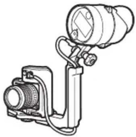
natural_image
Technical line drawing of a camera or optical instrument with lens and mounted components (no text or symbols)플래시 랼프의 붙이 청색인 경우
플래시 래프의 붙이 청색인 경유주
3 촬영합니다.
플래시 레벨
natural_image
Technical line drawings of four different camera components: a DSLR camera, a lens, a bracket, and a spring-loaded tool (no text or labels present)2 장치를 물에 담 recib니다.
natural_image
Illustration of a hand using a magnifying glass to adjust a component, with a close-up of the device on a flat surface (no text or symbols)Kr
5그늘에서 말려줍니다.
natural_image
Technical line drawing of a mechanical device with a cylindrical component and a separate motor housing (no text or symbols)Kr
유지관리
natural_image
Line drawing of two hands holding a curved object, possibly a wire or fiber (no text or symbols)40링홈을점검합니다.
natural_image
Mechanical diagram showing a piston assembly with a hand adjusting the shaft (no text or symbols present)50 링에 그리스를 도포합니다.
natural_image
Illustration of two hands holding a smartphone with a circular lens and motion lines (no text or symbols)60 링을 다시 삽입합니다.
No reproduction in any form of this manual, in whole or in part (except for brief quotation in critical articles or reviews), may be made without written authorization from NIKON CORPORATION.
MSIP-REI-NKR-SB-N10

제조연월 :
모델명:SB-N10
제조자:Nikon Corporation
제조국가:일본
상호명:(주) 니콘이미징코리아
NIKON CORPORATION
Printed in Japan