HCH2100ACS - Basket HAIER - Free user manual and instructions
Find the device manual for free HCH2100ACS HAIER in PDF.
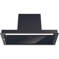
| Product Type | Wall-Mounted Range Hood |
| Brand | Haier |
| Model | HCH2100ACS |
| Available Widths | 24" (61 cm), 30" (76.2 cm), 36" (91.4 cm) |
| Power Supply | 120 V, 60 Hz, 15 A, 3-prong grounded plug |
| Extraction Power | Not specified in the manual, but suitable for domestic use |
| Controls | On/Off buttons, 3 fan speeds, lighting |
| Lighting | 2 halogen bulbs (type and wattage not specified, replace with bulbs of same type) |
| Filters | Washable metal grease filter, optional charcoal filter (recirculation) |
| Venting | 6" (15.2 cm) round duct to the outside or recirculation with special kit |
| Recommended Mounting Height | Minimum 24" (61 cm) above electric cooktop, 30" (76 cm) above gas cooktop, recommended maximum 36" (91.4 cm) |
| Material | Stainless steel (probable) |
| Noise Level | Not specified, but multi-speed fan for quiet operation |
| Filter Maintenance | Metal grease filter: wash in dishwasher or by hand; charcoal filter: replace every 6 months under normal use |
| Warranty | 2 years parts and labor (in-home service) |
| Safety | Safety shut-off in case of excessive heat, must unplug before maintenance |
| Available Replacement Parts | Grease filters, charcoal filters, halogen bulbs, power cord |
Frequently Asked Questions - HCH2100ACS HAIER
User questions about HCH2100ACS HAIER
0 question about this device. Answer the ones you know or ask your own.
Ask a new question about this device
Download the instructions for your Basket in PDF format for free! Find your manual HCH2100ACS - HAIER and take your electronic device back in hand. On this page are published all the documents necessary for the use of your device. HCH2100ACS by HAIER.
USER MANUAL HCH2100ACS HAIER
24", 30" and 36" Wall-Mount Range Hood
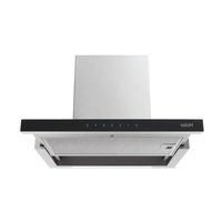
natural_image
3D rendering of a metallic industrial chimney or cover plate with mounting flanges (no text or symbols)TABLE OF CONTENTS
RANGE HOOD SAFETY INSTRUCTIONS....2
INSTALLATION REQUIREMENTS....5
Tools and Parts....5
Location Requirements ....5
Venting Requirements 6
Electrical Requirements 8
INSTALLATION INSTRUCTIONS......8
Step 1 - Unpack Range Hood ....8
Step 2 - Install Mounting Screws....9
Step 3 - Install Vent Cover Bracket....9
Step 4 - Complete Preparation ...... 10
Step 5 - Install Range Hood....10
Step 6 - Connect Vent System (non-vented installation only) ...... 12
Step 7 - Make Electrical Connection....13
Step 8 - Install Vent Covers....13
Step 9 - Complete Installation ....14
RANGE HOOD USE....14
Range Hood Controls 15
RANGE HOOD CARE 15
Cleaning 15
TROUBLESHOOTING....19
LIMITED WARRANTY 20
RECORD KEEPING
Thank you for purchasing this Haier product. This user manual will help you get the best performance from your new hood.
For future reference, record the model and serial number located inside of the hood, and the date of purchase.
Staple your proof of purchase to this manual to aid in obtaining warranty service if needed.
Model number
Serial number
Date of purchase
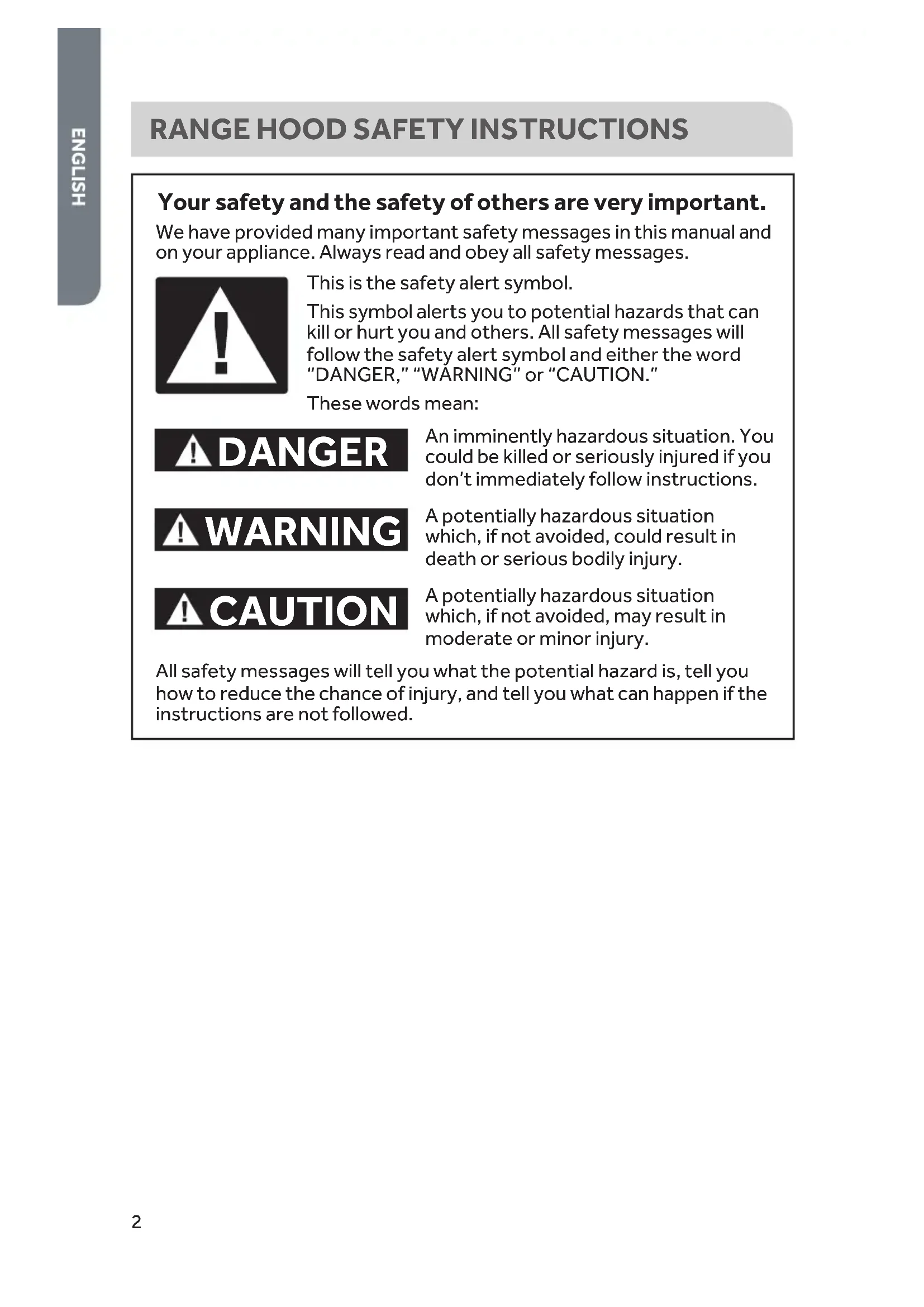
RANGE HOOD SAFETY INSTRUCTIONS
Your safety and the safety of others are very important.
We have provided many important safety messages in this manual and on your appliance. Always read and obey all safety messages.

text_image
Warning symbol with exclamation mark inside a triangle, commonly used to indicate caution or hazard.This is the safety alert symbol.
This symbol alerts you to potential hazards that can kill or hurt you and others. All safety messages will follow the safety alert symbol and either the word "DANGER," "WARNING" or "CAUTION."
These words mean:
! DANGER
An imminently hazardous situation. You could be killed or seriously injured if you don't immediately follow instructions.
WARNING
A potentially hazardous situation which, if not avoided, could result in death or serious bodily injury.
CAUTION
A potentially hazardous situation which, if not avoided, may result in moderate or minor injury.
All safety messages will tell you what the potential hazard is, tell you how to reduce the chance of injury, and tell you what can happen if the instructions are not followed.
IMPORTANT SAFETY INSTRUCTIONS
WARNING: To reduce the risk of fire, electrical shock, injury to persons, or damage when using the range hood, follow basic precautions, including the following:
- This appliance is intended for normal family household use only.
- Before servicing or cleaning the unit, switch power off at service panel and lock the service disconnecting means to prevent power from being switched on accidentally. When the service disconnecting means cannot be locked, securely fasten a prominent warning device, such as a tag, to the service panel.
- Installation work and electrical wiring must be done by qualified person(s) in accordance with all applicable codes and standards, including fire-rated construction.
- Do not operate any fan with a damaged cord or plug. Discard fan or return to an authorized service facility for examination and/or repair.
- Sufficient air is needed for proper combustion and exhausting of gases through the flue (chimney) of fuel burning equipment to prevent backdrafting. Follow the heating equipment manufacturer's guideline and safety standards such as those published by the National Fire Protection Association (NFPA), the American Society for Heating, Refrigeration and Air Conditioning Engineers (ASHRAE), and the local code authorities.
- When cutting or drilling into wall or ceiling; do not damage electrical wiring and other utilities.
- Ducted fans must always be vented outdoors.
- For general ventilating use only. Do not use to exhaust hazardous or explosive materials and vapors.
- To reduce risk of fire and to properly exhaust air, be sure to duct air outside - do not vent exhaust air into spaces within walls or ceilings, attics or into crawl spaces, or garages.
- To reduce the risk of fire, use only metal ductwork.
- To reduce the risk of fire or electrical shock, do not use this fan with any solid-state speed control device.
IMPORTANT SAFETY INSTRUCTIONS
- Wipe up spill over immediately.
- Do not allow aluminum foil, plastic, paper or cloth to come in contact with a hot surface.
- Do not allow pans to boil dry.
• Always have a working smoke detector near the kitchen. - Moist or damp pot holders on hot surfaces may result in burns from steam. Do not let pot holder touch hot heating elements. Do not use a towel or other bulky cloth.
WARNING: TO REDUCE THE RISK OF A RANGE TOP GREASE FIRE:
- Never leave surface units unattended at high settings. Boilovers cause smoking and greasy spillovers that may ignite. Heat oils slowly on low or medium settings.
- Always turn hood ON when cooking at high heat or when flambeing food (i.e. Crepes Suzette, Cherries Jubilee, Peppercorn Beef Flambé).
- Clean ventilating fans frequently. Grease should not be allowed to accumulate on fan or filter.
- Use proper pan size. Always use cookware appropriate for the size of the surface element.
WARNING: TO REDUCE THE RISK OF INJURY TO PERSONS IN THE EVENT OF A RANGE TOP GREASE FIRE, OBSERVE THE FOLLOWING. ^a
- SMOTHER FLAMES with a close fitting lid, cookie sheet, or metal tray, then turn off the burner. BE CAREFUL TO PREVENT BURNS. If the flames do not go out immediately, EVACUATE AND CALL THE FIRE DEPARTMENT.
- NEVER PICK UP A FLAMING PAN - you may be burned.
- DO NOT USE WATER, including wet dishcloths or towels - a violent steam explosion will result.
• Use an extinguisher ONLY if:
- You know you have a class ABC extinguisher, and you already know how to operate it.
- The fire is small and contained in the area where it started.
- The fire department is being called.
- You can fight the fire with your back to an exit.
^a Based on “Kitchen Fire Safety Tips” published by NFPA.
READ AND SAVE THESE INSTRUCTIONS
INSTALLATION REQUIREMENTS
TOOLS AND PARTS
Gather the required tools and parts before starting installation. Read and follow the instructions provided with any tools listed here.
Tools needed
- Level
- Drill with 1 14 , 1 / 8 , and 5 / 16 " Drill Bits
- Pencil
• Wire Stripper or Utility Knife - Tape Measure or Ruler
- Pliers
- Caulking Gun
• Caulking Compound (weatherproof)
- Vent Clamps
• Jigsaw or Keyhole Saw
- Flat-blade Screwdriver
- Metal Snips
• Phillips Screwdriver
• Metric Hex Key Set
For non-vented (recirculating) installations, you will also need:
- 6" (15.2 cm) dia. round metal vent duct - length required is determined by ceiling height.
Parts supplied
Remove parts from packages. Check that all parts are included.
• 120 V Power Cord (with 3 prong plug)
- Hood Canopy Assembly (blower, vent transition, light bulb and canopy glass [pre-installed])
• Metal Grease Filter
- Vent Cover Support Bracket (attached to vent cover)
- Two-Piece Vent Cover
- 4 x 8 Screws (4)
- 5 x 45 mm Mounting Screws (6)
- 8 x 40 Wall Anchors (2)
• 10 x 50 mm Wall Anchors (4)
LOCATION REQUIREMENTS
IMPORTANT: Observe all governing codes and ordinances.
Have a qualified technician install the range hood. It is the installer's responsibility to comply with installation clearances specified on the model/serial rating plate. The model/serial rating plate is located behind the left filter on the rear wall of the vent hood.
Canopy hood location should be away from strong draft areas, such as windows, doors and strong heating vents.
Grounded electrical outlet is required. See "Electrical Requirements" section.
FOR MOBILE HOME INSTALLATIONS
The installation of this range hood must conform to the Manufactured Home Construction Safety Standards, Title 24 CFR, Part 328 (formerly the Federal Standard for Mobile Home Construction and Safety, Title 24, HUD, Part 280) or when such standard is not applicable, the standard for Manufactured Home Installation 1982 (Manufactured Home Sites, Communities and Setups) ANSI A225.1/NFPA 501A, or latest edition, or with local codes.
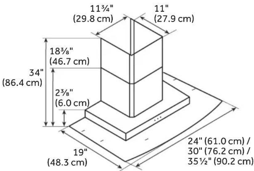
PRODUCT DIMENSIONS
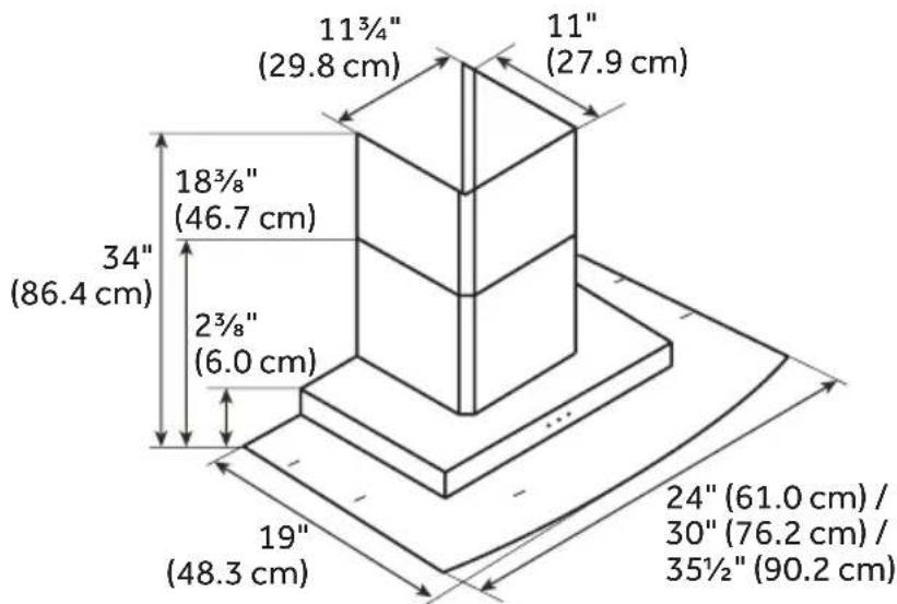
text_image
11¾"(29.8 cm) 11" (27.9 cm) 18¾"(46.7 cm) 34" (86.4 cm) 2¾"(6.0 cm) 19" (48.3 cm) 24"(61.0 cm) / 30"(76.2 cm) / 35½"(90.2 cm)VENTING REQUIREMENTS
Makeup Air
Local building codes may require the use of makeup air systems when using ventilation systems greater than specified CFM of air movement. The specified CFM varies from locale to locale.
Consult your HVAC professional for specific requirements in your area.
General Venting
The vent hood is designed to vent through the roof or wall. To vent through a wall, a 90° elbow is needed.
- Vent system must terminate to the outdoors except for non-vented (recirculating) installations.
- Do not terminate the vent system in an attic or other enclosed area.
- If it is not possible to vent cooking fumes outside, the hood can be used for a non-vented (recirculating) installation by attaching a deflector and a charcoal filter. A Recirculating Kit is available for purchase.
- Use metal vent only. Rigid metal vent is recommended. Plastic or metal foil vent is not recommended.
- The length of vent system and number of elbows should be kept to a minimum to provide efficient performance.
NOTE: A 90° elbow must be installed immediately above the hood.
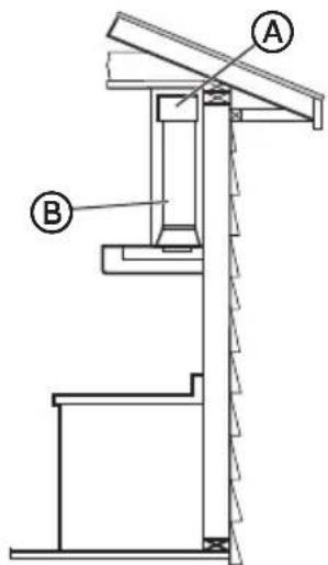
Roof Venting:
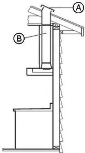
text_image
Technical diagram of a mechanical assembly with labeled components A and BⒶ Roof Cap
⑧ 6" (15.2 cm) round vent
Wall Venting:
text_image
Technical diagram of a mechanical assembly with labeled components A and BⒶ Wall Cap
⑧ 6" (15.2 cm) round vent
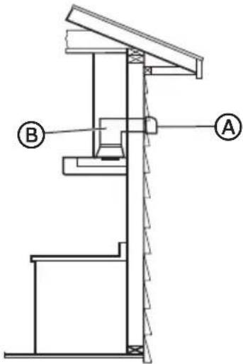
Non-Vented (recirculating):
text_image
Technical diagram showing a mechanical assembly with labeled components A and BⒶ Deflector
⑧ 6" (15.2 cm) round vent
ELECTRICAL REQUIREMENTS
Observe all governing codes and ordinances.
Ensure that the electrical installation is adequate and in conformance with National Electrical Code, ANSI/NFPA 70 (latest edition), or CSA Standards C22.1-94, Canadian Electrical Code, Part 1 and C22.2 No. 0-M91 (latest edition) and all local codes and ordinances.
If codes permit and a separate ground wire is used, it is recommended that a qualified electrician determine that the ground path is adequate.
A copy of the above code standards can be obtained from:
National Fire Protection Association
1 Batterymarch Park
Quincy, MA 02169-7471
CSA International
8501 East Pleasant Valley Road
Cleveland, OH 44131-5575
It is important to make sure you have the proper electrical connection.
RECOMMENDED GROUNDING METHOD
A 120 volt, 60 Hz, AC only, 15-amp fused, grounded electrical supply is required. Use an outlet that cannot be turned off by a switch. Do not use an extension cord.
NOTE: Before cleaning, or removing a light bulb, turn vent hood off, and then disconnect the vent hood from the electrical source. When you are finished, reconnect the vent hood to the electrical source.
INSTALLATION INSTRUCTIONS
WARNING

Electrical Shock Hazard
Disconnect power before installing unit.
Failure to do so can result in death, fire, or electric shock.
Disconnect power before installing range hood.
STEP 1 - UNPACK RANGE HOOD
- Select a flat surface for assembling the range hood and cover the surface.
WARNING
Excessive Weight Hazard
Use two or more people to move and install range hood.
Failure to do so can result in back or other injury.
- Using two or more people, lift the range hood assembly onto the covered surface.
STEP 2 - INSTALL MOUNTING SCREWS
- Determine and mark the centerline on the wall where the canopy hood will be installed.
- Select a mounting height between a minimum of 24" (61.0 cm) for an electric cooking surface, a minimum of 30" (76 cm) for a gas cooking surface, and a suggested maximum of 36" (91.4 cm) above the range to the bottom of the hood. Mark a reference line on the wall.
- Mark centers of the fastener locations on the wall.
IMPORTANT: All screws must be installed into wood. If there is no wood to screw into, additional wall framing supports may be required.
-
Drill 316 " (4.8 mm) pilot holes at all locations where screws are being installed into wood.
-
Install the two - 5 x 45 mm mounting screws. Leave a 14 " (6.4 mm) gap between the wall and the back of the screw head to slide range hood into place.
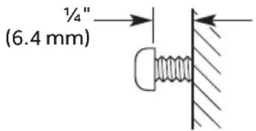
text_image
(6.4 mm) ¼"STEP 3 - INSTALL VENT COVER BRACKET
- Remove support bracket from vent cover.
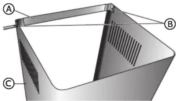
text_image
A B CⒶ Support Bracket
B Screws
© Vent Cover
- Attach support bracket to wall flush to the ceiling using two - 5 x 45 mm screws.
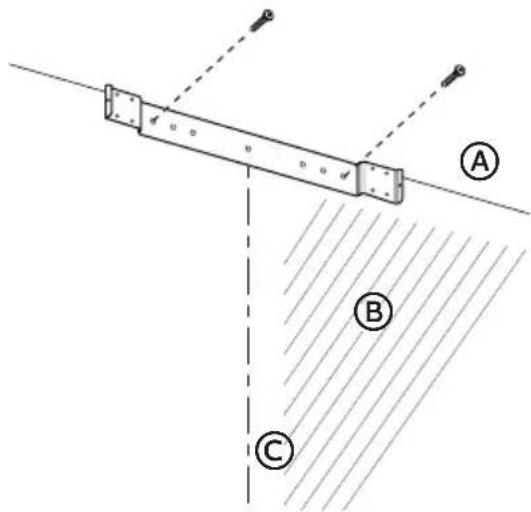
text_image
Diagram showing a mechanical or structural setup with labeled points A, B, and C, and directional arrows indicating motion or force.
Ceiling

Wall

Centerline
STEP 4 - COMPLETE PREPARATION
- Determine the required height for the home power supply cable and drill a 114 " (3.2 cm) hole at this location.
- Run the home power supply cable according to the National Electrical Code or CSA Standards and local codes and ordinances. There must be enough 12 " conduit and wires from the fused disconnect (or circuit breaker) box to make the connection in the hood's electrical terminal box.
NOTE: Do not reconnect power until installation is complete.
- Use caulk to seal all openings.
STEP 5 - INSTALL RANGE HOOD
IMPORTANT:
- If the range hood is being installed above an installed range, ensure the range is turned off and has cooled completely before beginning installation.
- Do not remove the plastic film from the range hood until installation is complete.
WARNING
Excessive Weight Hazard
Use two or more people to move and install range hood.
Failure to do so can result in back or other injury.
WARNING

Electrical Shock Hazard
Plug into a grounded 3 prong outlet.
Do not remove the ground prong from the power cord plug.
Do not use an adapter.
Do not use an extension cord.
Failure to do so can result in death, fire or electrical shock.
- Before mounting the range hood, plug the range hood into a grounded 3 prong outlet to test all functions for proper operation.
- Blower works at all speeds.
• Lights turn on and off.
• The damper flaps open when the blower is on.
- Using two or more people, hang range hood on two mounting screws through the mounting slots on back of hood.
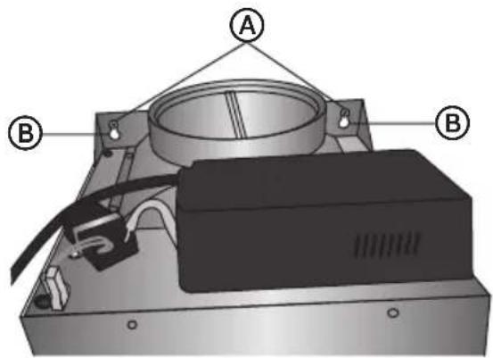
text_image
Technical diagram of an electronic device with labeled components A and B, showing internal components and wiring.
Mounting Screws

Mounting Slots
-
Remove the grease filter. See "Range Hood Care" section.
-
Level the range hood and tighten upper mounting screws.
-
Install two 5 x 45 mm lower mounting screws and tighten.
-
Fit vent system over the exhaust outlet.
-
Seal connection with clamps.
-
Check that back draft dampers work properly.
STEP 6 - CONNECT VENT SYSTEM (NON-VENTED INSTALLATION ONLY)
IMPORTANT: If the air deflector is not installed correctly, air will flow freely inside the vent duct covers instead of being forced out of the vent openings on the side of the vent duct cover.
- Using the four screws (provided) in the Recirculation Kit, fasten the air deflector to the duct cover bracket.
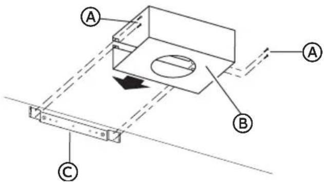
text_image
Technical diagram showing a mechanical assembly with labeled components A, B, and C, including directional arrows and a central circular feature.Ⓐ Assembly Screws
Ⓑ Air Deflector
ⓒ Duct Cover Bracket
- Measure from the bottom of the air deflector to the bottom of the hood exhaust outlet.
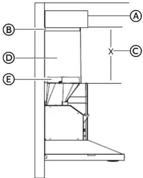
text_image
A B D E X C(A) Air deflector (B) Vent clamp (C) X = length to cut vent duct (D) Vent duct (E) Exhaust outlet
-
Cut the duct to the measured size (X).
-
Remove the air deflector.
-
Slide the duct onto the bottom of the air deflector.
-
Place the assembled air deflector and duct over the exhaust outlet from the hood.
-
Using the four screws removed in Step 4, reattach the air deflector to the duct cover bracket.
-
Seal connections with vent clamps.
WARNING

Electrical Shock Hazard
Plug into a grounded 3 prong outlet.
Do not remove the ground prong from the power cord plug.
Do not use an adapter.
Do not use an extension cord.
Failure to do so can result in death, fire or electrical shock.
- Plug into a grounded 3 prong outlet.
STEP 8 - INSTALL VENT COVERS
NOTE: Remove the white film from the vent covers, as needed, prior to assembly and installation. Handle the vent covers gently to avoid scratching the finish.
- When using both upper and lower vent covers, push lower cover down onto hood and lift upper cover to ceiling and install with two 4 x 8 mm screws (provided).
NOTE: For vented installations, the upper vent cover may be reversed to hide slots.
text_image
A B C D(A) 4 x 8 mm Screw
B Slots
© Upper Vent Cover
(D) Lower Vent Cover
- Using two screws (provided) fasten the bottom of the duct to the hood.
STEP 9 - COMPLETE INSTALLATION
- For non-vented (recirculating) installations only, install charcoal filters over the blower motor intakes on both the left-hand and right-hand sides of the blower motor. See the "Range Hood Care" section.
- Install metal grease filters. See the "Range Hood Care" section.
- Remove any remaining film from the vent covers.
RANGE HOOD USE
The range hood is designed to remove smoke, cooking vapors and odors from the cooktop area. For best results, start the hood before cooking and allow it to operate 15 minutes after the cooking is complete to clear all smoke and odors from the kitchen.
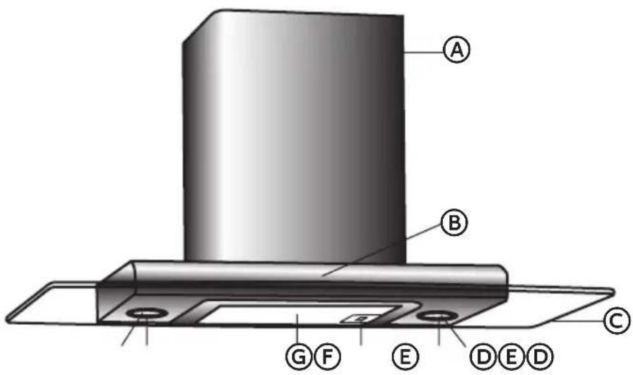
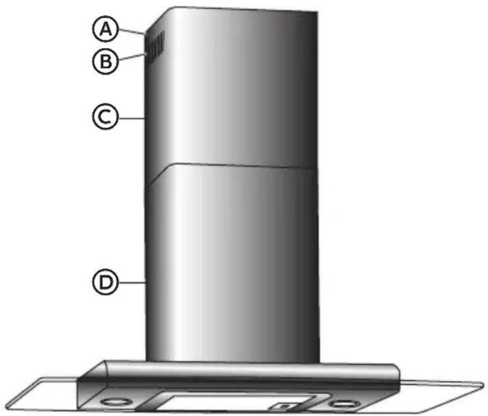
text_image
A B G F E D E D CⒶ Duct Cover
B Control Panel
© Glass Canopy
D Lamp Cover
E Halogen Bulb
F Grease Filter Release
G Grease Filter
RANGE HOOD CONTROLS
The hood controls are located on the front side of the canopy.
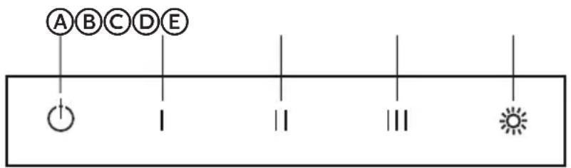
text_image
A B C D E I II III SⒶ Power/Off
B Speed 1
© Speed 2
D Speed 3
E Light
OPERATING THE LIGHT
The light button controls both lights. Press once for On and again for Off.
The Blower Speed buttons turn the blower on and control the blower speed and sound level for quiet operation. The speed can be changed anytime during fan operation by pressing the desired Blower Speed button.
RANGE HOOD CARE
CLEANING
WARNING

Electrical Shock Hazard
Disconnect power before cleaning.
Failure to do so can result in death or electrical shock.
IMPORTANT: Clean the hood and grease filters frequently according to the following instructions. Replace grease filters before operating hood.
EXTERIOR SURFACES:
To avoid damage to the exterior surface, do not use steel wool or soap-filled scouring pads.
Always wipe dry to avoid water marks.
Cleaning Method:
• Liquid detergent and water, or all-purpose cleanser
- Wipe with damp soft cloth or nonabrasive sponge, then rinse with clean water and wipe dry.
METAL GREASE FILTER
- Slide the filter release to the left, and then pull downward to remove the grease filter.
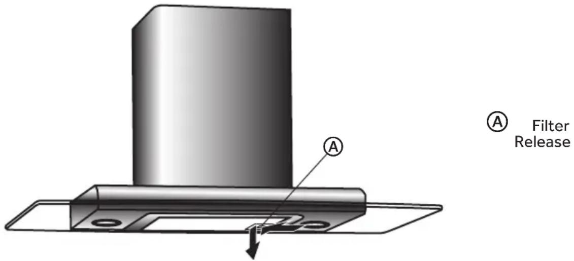
text_image
A Filter Release A- Wash the metal filter, as needed, either in the dishwasher or with a solution of hot water and dish detergent.
- Replace the metal grease filter.
CHARCOAL FILTERS (NON-VENTED [RECIRCULATION] INSTALLATIONS ONLY)
The charcoal filter should last for up to 6 months with normal use. The charcoal filter is not washable; it must be replaced with a new filter.
TO REPLACE CHARCOAL FILTERS:
- Follow the previous steps to remove the metal grease filter from the hood.
- Locate the two studs extending from the top and bottom of the intake on the right and left side of the blower.
Blower Intake - Right-hand Side
text_image
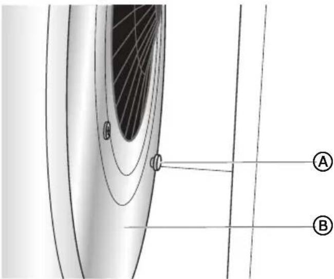
Technical diagram showing a curved structure with labeled points A and B, and concentric lines indicating depth or flow.Ⓐ Metal Stud (bottom) (top stud not shown)
⑧ Blower
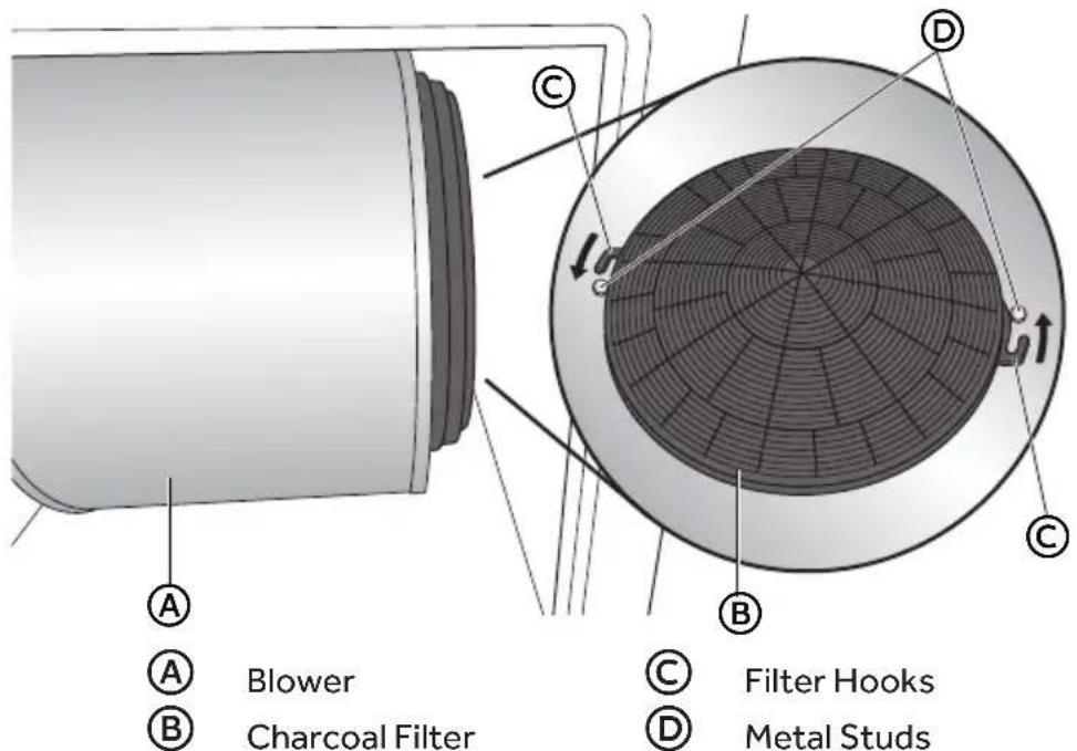
- Insert the charcoal filter onto the intake of the blower on the left-hand and right-hand sides, and then rotate each filter slightly until the hooks on the filter wrap around the studs.
Blower Intake - Right-hand Side
text_image
A B Blower C Charcoal Filter D C Filter Hooks D Metal Studs- Replace metal grease filter.
WARNING

Electrical Shock Hazard
Make sure the range hood lights are cool and power to the range hood has been turned off before replacing the light bulb(s).
The lenses must be in place when using the range hood. The lenses serve to protect the light bulb from breaking.
The lenses are made of glass. Handle carefully to avoid breakage.
Failure to do so could result in death, electric shock, cuts or burns.
Turn off the range hood light to allow the bulb to cool. To avoid damage or decreasing the life of the new bulb, do not touch bulb with bare fingers. Wear cotton gloves or use a tissue when replacing the light bulb.
If a new bulb does not illuminate, first check that it is inserted correctly in the socket before calling service.
- Disconnect power.
- Insert a flat-blade screwdriver, and gently pry off the light shield.
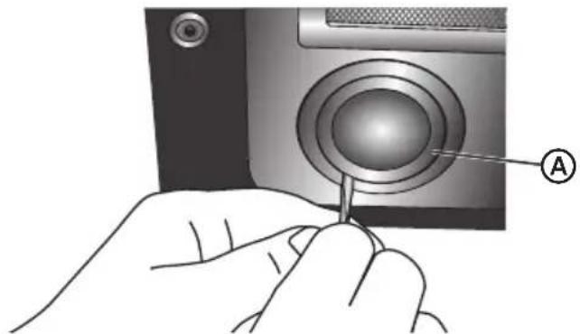
natural_image
Illustration of a hand inserting a cable into a camera lens (no text or symbols present)
Light Shield
- Gently pull the burned out bulb from the socket.
- Avoiding contact with skin, insert a new halogen bulb of the same size, shape and wattage into the socket.
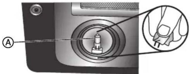
text_image
Diagram showing a device's internal component with labeled parts and a magnified inset highlighting the hand holding a key.
Bulb
- Align the three tabs of the light shield with the holes in the opening and push up to snap it in place.
- Reconnect power.
TROUBLESHOOTING
First try the solutions suggested here to possibly avoid the cost of a service call.
| Problem Possible Reason Solution | ||
| Hood doesn't work. | Electric Supply Plug power cord into power source. | |
| Poor Airflow Aluminum grease filters are clogged. | Clean and dry the filters, and then reassemble. | |
| Motor running, but no airflow. | Butterfly valve jammed. Call for service. | |
| After running for a while, the motor stops. | The high temperature safety device is activated. | The kitchen is not sufficiently ventilated. |
| The hood is installed too close to the stove. | The hood must be a minimum of 24" (61 cm) for an electric cooking surface, and a minimum of 30" (76 cm) for a gas cooking surface. | |
| Strong cooking smell | Charcoal filters are not installed. | In re-circulating mode, charcoal filters must be installed. |
| Oil dripping onto stove | Oil cup missing or not installed. | Replace aluminum filter and replace oil cup. |
| Aluminum grease filter saturated. | Wash the aluminum grease filters. | |
| Whirring sound Fan blade problem Call for service. | ||
FOR MORE HELP, VISIT HAIERAMERICA.COM OR CALL THE CONSUMER HELP LINE AT 1-877-337-3639.
LIMITED WARRANTY
IN-HOME SERVICE
FULL TWO YEAR WARRANTY
For 24 months from the date of original retail purchase, Haier will repair or replace any part free of charge including labor that fails due to a defect in materials or workmanship.
Haier may replace or repair at their sole discretion any part, sub system including the entire product.
Product must be accessible, without encumbrance and installed properly to receive warranty repair service.
LIMITED WARRANTY
NOTE: This warranty commences on the date the item was purchased, and the original purchase receipt must be presented to the authorized service representative before warranty repairs are rendered.
Exceptions: Commercial Use Warranty
90 days labor from date of original purchase
90 days parts from date of original purchase
No other warranty applies.
FOR WARRANTY SERVICE
All service must be performed by a Haier authorized service center. For the name and telephone number of the nearest authorized service center, please call 1-877-337-3639.
Before calling please have available the following information:
Model number and serial number of your appliance. The name and address of the dealer you purchased the unit from and the date of purchase.
A clear description of the problem.
A proof of purchase (sales receipt).
This warranty covers home appliance services within the contiguous United States and Canada and where available in Alaska, Hawaii and Puerto Rico.
What is not covered by this warranty:
Replacement or repair of household fuses, circuit breakers, wiring or plumbing.
A product whose original serial number has been removed or altered.
Any service charges not specifically identified as normal such as normal service area or hours.
Replacement of light bulbs.
Damage to clothing.
Damage incurred in shipping.
Damage caused by improper installation or maintenance.
Damage from misuse, abuse accident, fire, flood, or acts of nature.
Damage from service other than an authorized Haier dealer or service center.
Damage from incorrect electrical current, voltage or supply.
Damage resulting from any product modification, alteration or adjustment not authorized by Haier.
Adjustment of consumer operated controls as identified in the owner's manual.
Hoses, knobs, lint trays and all attachments, accessories and disposable parts.
Labor, service transportation, and shipping charges for the removal and replacement of defective parts beyond the initial 24-month period.
Damage from other than normal household use.
Any transportation and shipping charges.
THIS LIMITED WARRANTY IS GIVEN IN LIEU OF ALL OTHER WARRANTIES, EXPRESS ED OR IMPLIED, INCLUDING BUT NOT LIMITED TO, THE WARRANTIES OF MERCHANTABILITY AND FITNESS FOR A PARTICULAR PURPOSE
The remedy provided in this warranty is exclusive and is granted in lieu of all other remedies.
This warranty does not cover incidental or consequential damages, so the above limitations may not apply to you. Some states do not allow limitations on how long an implied warranty lasts, so the above limitations may not apply to you.
This warranty gives you specific legal rights, and you may have other rights, which vary from state to state.
Haier America
Wayne, NJ 07470
TABLE DES MATIÈRES
SÉCURITÉ DE LA HOTTE 22
EXIGENCES D'INSTALLATION....26
text_image
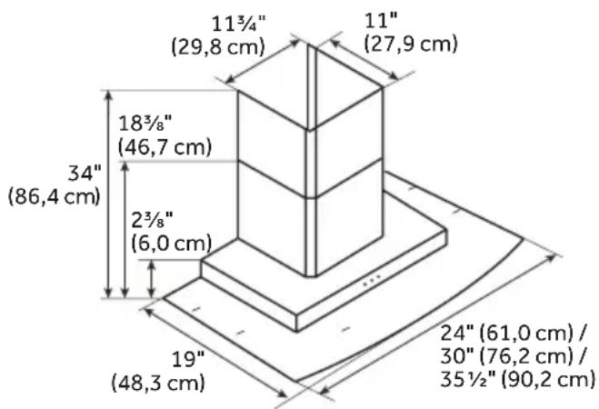
Warning sign with exclamation mark inside a triangle, commonly used to indicate caution or hazard.DIMENSIONS DU PRODUIT
text_image
11¾"(29.8 cm) 11"(27.9 cm) 18¾"(46.7 cm) 34"(86.4 cm) 2¾"(6.0 cm) 19"(48.3 cm) 24"(61.0 cm) / 30"(76.2 cm) / 35½"(90.2 cm)EXIGENCES CONCERNANT L'ÉVACUATION
Air d'appoint
text_image
Technical diagram of a mechanical assembly with labeled components A and Btext_image
Technical diagram of a mechanical assembly with labeled components A and Btext_image
Technical diagram of a mechanical device with labeled components A and B
Déflecteur

National Fire Protection Association
1 Batterymarch Park
Quincy, MA 02169-7471
CSA International
8501 East Pleasant Valley Road
Cleveland, OH 44131-5575
text_image
Diagram showing a mechanical or structural component with labeled points A, B, and C, and directional arrows indicating motion or force.A
Plafond
B
Mur
©
Axe central
ÉTAPE 4 - ACHÈVEMENT DE LA PRÉPARATION
text_image
Technical diagram of an electronic device with labeled components A and B, showing internal components and wiring.
Vis de montage

Encoches de montage
text_image
Technical diagram showing a mechanical assembly with labeled components A, B, and C, including directional arrows and a central circular feature.
Vis d'assemblage

Déflecteur d'air

text_image
A B D E C Xtext_image
A B G F E D E D Cnatural_image
3D diagram of a metal shelf with a cylindrical component and a labeled section (A), showing internal structure and mounting base (no text or symbols beyond label)
text_image
Diagram showing a curved structure with labeled points A and B, likely illustrating a geometric or physical concept.text_image
Technical diagram of a mechanical component with labeled parts A, B, C, D and directional arrows indicating motion or flow.REPLACEMENT D'UNE AMPOULE
⚠ AVERTISSEMENT

natural_image
Hand inserting a cable into a camera lens (no text or symbols visible)A
Protège- ampoule
text_image
Diagram showing a device's internal component with labeled point A and magnified detail viewA
Ampoule
text_image
Warning symbol with exclamation mark inside a triangleDIMENSIONES DEL PRODUCTO
text_image
11¾"(29,8 cm) 11"(27,9 cm) 18¾"(46,7 cm) 34"(86,4 cm) 2¾"(6,0 cm) 19"(48,3 cm) 24"(61,0 cm) / 30"(76,2 cm) / 35½"(90,2 cm)text_image
Technical diagram of a mechanical assembly with labeled components A and Btext_image
Technical diagram of a mechanical assembly with labeled components A and Btext_image
Technical diagram of a mechanical assembly with labeled components A and BⒶ Desviador
National Fire Protection Association 1 Batterymarch Park Quincy, MA 02169-7471
CSA International 8501 East Pleasant Valley Road Cleveland, OH 44131-5575
text_image
Diagram showing a mechanical or structural component with labeled points A, B, and C, and directional arrows indicating motion or force.Ⓐ Techo
B Pared
© Central
text_image
Technical diagram of a device with labeled components A and B, showing internal components like a speaker and circuit board.text_image
Technical diagram showing a mechanical assembly with labeled components A, B, and C, including directional arrows and a central circular feature.text_image
A B G F E D E D Cnatural_image
3D technical diagram of a metal bracket with mounting holes and a labeled component (A), showing no text or symbols beyond the label.A
text_image
Diagram of a curved structure with labeled points A and B, showing internal grid patterns and directional arrows.A
text_image
Technical diagram of a mechanical component with labeled parts A, B, C, D and directional arrows indicating motion or flow.A
Soplador
B
Filtro de carbón
©
Ganchos del filtro
D
Clavijas de metal
natural_image
Illustration of a hand inserting a cable into a camera lens (no text or symbols present)
Pantalla de z
text_image
Diagram showing a camera dial with a labeled component and a magnified view of the foot's finger.
Foco
Haier may replace or repair at their sole discretion any part, sub system including the entire product.
Product must be accessible, without encumbrance and installed properly to receive for warranty repair service.
GARANTÍA LIMITADA
If you have a problem with this product, please contact the
"Haier Customer Satisfaction Center" at
1-877-337-3639.
DATED PROOF OF PURCHASE, MODEL #, AND SERIAL #
REQUIRED FOR WARRANTY SERVICE
IMPORTANT
HCH2100ACS, HCH3100ACS
HCH6100ACS
Issued: January 2016 Printed in China Part # 0570000064 REV B