HAPY72ES6XGG - Range hood HAIER - Free user manual and instructions

Find the device manual for free HAPY72ES6XGG HAIER in PDF.
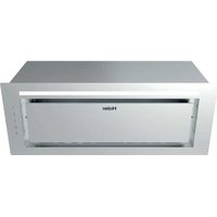
HAIER HAPY72ES6XGG - Range hood
📄 238 pages English EN Download 💬 AI Question 10 questions ⚙️ Specs
Notice HAIER HAPY72ES6XGG - page 2
Pick your language and provide your email: we'll send you a specifically translated version.
Product Type Range Hood
Brand Haier
Model HAPY72ES6XGG
Width (approximate) 72 cm
Minimum installation height 650 mm above the heating elements
Maximum installation height 750 mm above the heating elements
Power supply (typical) 220-240 V ~ 50 Hz
Number of speeds 3 speeds + Boost
Boost function Runs for 5 minutes then returns to speed 3
Timer 15 minutes by default (activation by long press)
Lighting LED, to be replaced by technical service
Exhaust mode External exhaust or recirculation with charcoal filter
Grease filter Metal, washable (every 3 months)
Charcoal filter Replacement every 3 to 6 months (not washable)
Grease filter cleaning Water and neutral detergent or dishwasher
Maintenance Unplug before any operation
Safety Do not light a flame under the hood; do not open the gas meter without a pan
Usage Indoor and household use only
Maximum number of burners 4 cooking elements
Maximum negative pressure 4 Pa (4 x 10^-5 bar)
Electrical connection Power cord to be replaced by a professional if damaged

Frequently Asked Questions - HAPY72ES6XGG HAIER

At what height should the Haier HAPY72ES6XGG hood be installed?
The hood must be installed at a height between 650 mm (minimum) and 750 mm (maximum) above the heating elements or burners.
How to clean the grease filter?
Remove the metal filter, wash it in a solution of water and neutral liquid detergent, rinse thoroughly with lukewarm water and let dry. It is also dishwasher safe.
When to replace the charcoal filter?
The charcoal filter must be replaced every 3 to 6 months depending on use. It is not washable.
How to activate the timer function?
Press and hold the speed button for 2 seconds to activate the timer. The default duration is 15 minutes, after which the hood turns off automatically.
What to do if the LED lighting fails?
Contact technical service for replacement of the LED lighting system. It is not intended to be replaced by the user.
Can I use the hood in recirculation mode?
Yes, if you do not use your cooktop intensively, you can opt for recirculation mode. In this case, the air is returned to the kitchen and a charcoal filter is needed to remove odors.
How to use the Boost function?
Press the B button. The hood runs in Boost mode for 5 minutes, then automatically returns to speed 3.
Can children use the hood?
This appliance can be used by children aged at least 8 years under supervision. Cleaning and maintenance should not be performed by children unless they are over 8 and supervised.
What to do if the power cord is damaged?
Have it replaced by the manufacturer, after-sales service or a qualified electrician to avoid any risk of accident.
What are the safety distances to observe?
The hood must be installed at least 65 cm from the heating elements. Never check the filters when the hood is operating, do not touch the bulb within half an hour of use, and do not light a flame under the hood.

User questions about HAPY72ES6XGG HAIER

0 question about this device. Answer the ones you know or ask your own.

Ask a new question about this device

Your email remains private: it is only used to notify you if someone answers your question.

No questions yet. Be the first to ask one.

Download the instructions for your Range hood in PDF format for free! Find your manual HAPY72ES6XGG - HAIER and take your electronic device back in hand. On this page are published all the documents necessary for the use of your device. HAPY72ES6XGG by HAIER.

USER MANUAL HAPY72ES6XGG HAIER

Instruction Book

Information and advice

CAUTION: Accessible parts may become hot when used with cooking appliances.

In certain circumstances electrical appliance may be a danger hazard.

A) There must be adequate ventilation of the room when the cooker hood is used at the same time as appliances burning gas or other fuels. B) Do not check the status of the filters while the cooker hood is operating. C) Do not touch the light bulb within half an hour after appliance has been use. D) Do not light a flame under the cooker hood. E) Avoid opening gasometer when there is no pan on the stove, as it is damaging for the filters and a fire hazard. F) Constantly check food frying to avoid overheated oil splashing and becoming a fire hazard. G) Disconnect the electrical plug prior to any maintenance. H) Regulations concerning the discharge of air have to be fulfilled. I) When the range hood and appliances supplied with energy Other than electricity are simultaneously in operation. The negative pressure in the room must not exceed 4 Pa ( 4 × 10⁻⁵ bar)

Information and advice

CAUTION: Accessible parts may become hot when used with cooking appliances.

J) If the supply cord is damaged, it must be replaced by the manufacturer, its service agent or similarly qualified persons in order to avoid a hazard.
K) This appliance can be used by children aged from 8 years and above and persons with reduced physical, sensory or mental capabilities or lack of experience and knowledge if they have been given supervision or instruction concerning use of the appliance in a safe way and understand the hazards involved. Children shall not play with the appliance. Cleaning and user maintenance shall not be made by children unless they are older than 8 and supervised.

L) the range hood is intended to be installed over a hob having no more than four hob elements.

M) Indoor use and household use only

N) When the appliance is not in use and before cleaning, unplug the appliance from the outlet.

O) Attention ! Observe the warning in the instruction sheet concerning the operation of the appliance when air is discharged from the room

P) There is a fire risk if cleaning is not carried out in accordance with the instructions.

Information and advice

CAUTION: Accessible parts may become hot when used with cooking appliances.

Q) The air must not be discharged into a flue that is used for exhausting fumes from appliances burning gas or other fuels (not applicable to appliances that only discharge the air back into the room). I) Children should be supervised to ensure that they do not play with the appliance. S) Warning: Failure to install the screws or fixing device in accordance with these instructions may result in electrical hazards. T) The installation height of the hood shall not be less than 65 cm. U) The filter screen must be cleaned regularly, otherwise there is a danger of fire. V) The installation must be carried out according to the screws and positions required by the instructions, which will easily damage the connecting wires. W) If the supply cord is damaged, it must be replaced by the manufacturer, its service agent or similarly qualified persons in order to avoid a hazard.

HAIER HAPY72ES6XGG - 1

Information and advice

Check the voltage, frequency and power of the rating label on the body.

1
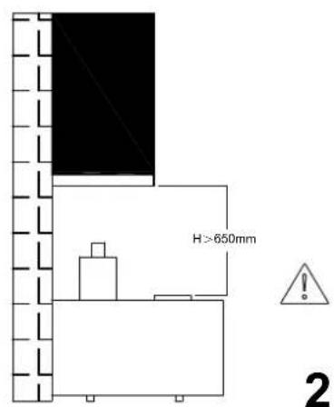
H > 650 mm, 2

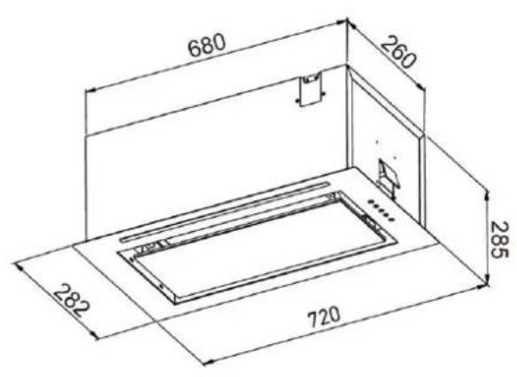
We recommend that after installation the bottom of the hood should be no less than 650 mm and no more than 750 mm above the stove's heating elements and burners.

HAIER HAPY72ES6XGG - Information and advice - 2

Information

The cooker hood must be installed and connected to flues where other appliances are installed and which run off other energy supplied different to electricity (water heaters, boilers, cookers (range/agas) etc.). The cooker hood must not be installed above a cooker with eye-level grills.

InstallationHAIER HAPY72ES6XGG - Information - 1
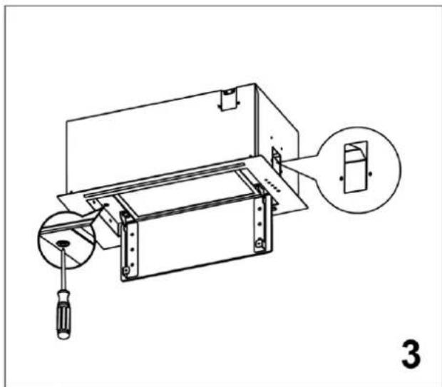
Technical line drawing of a mechanical device with a magnified inset showing a component (no text or symbols present).

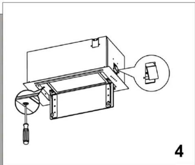
Technical line drawing of a mechanical device with a magnified inset showing a component (no text or symbols present).

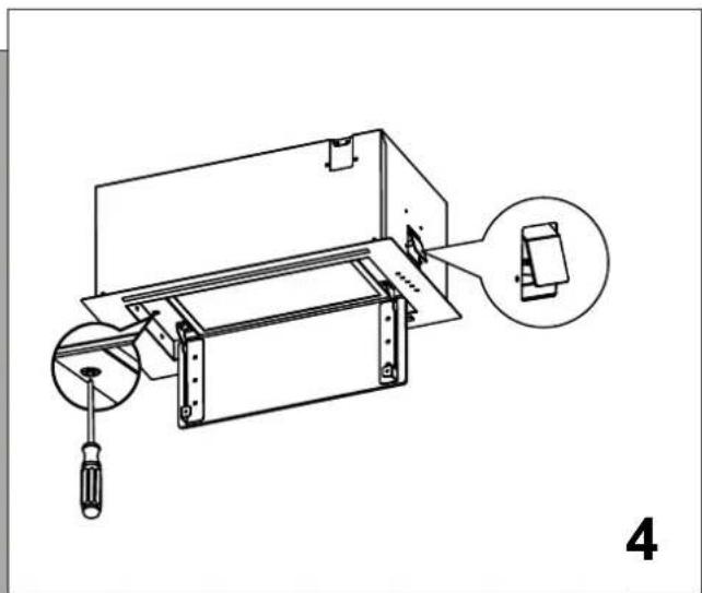
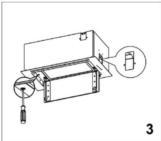
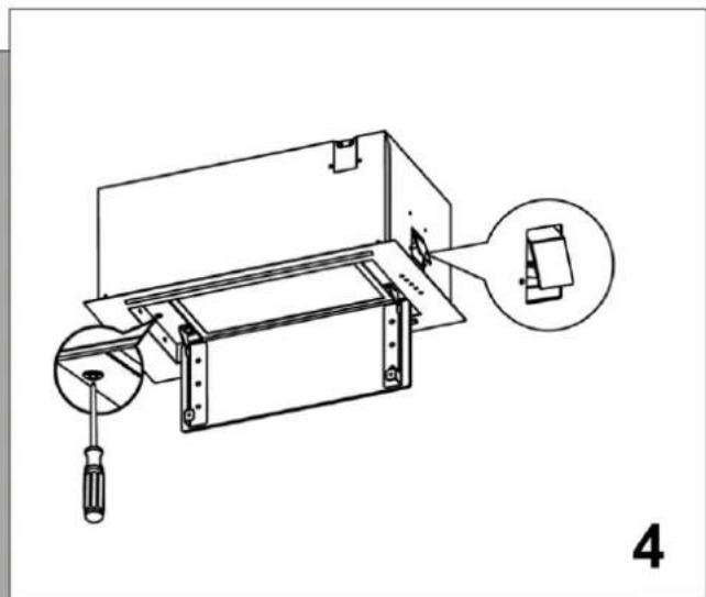
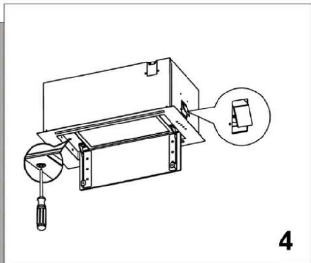
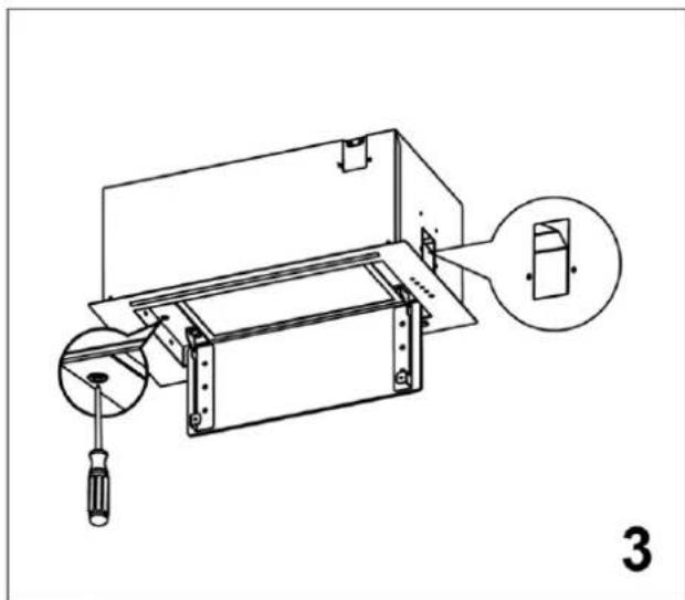
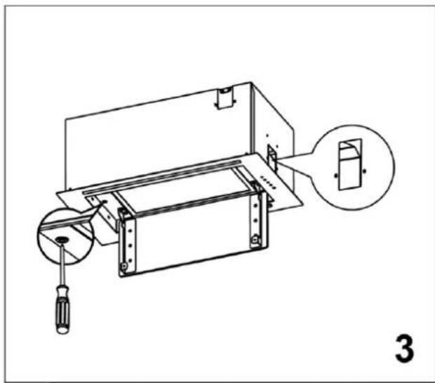
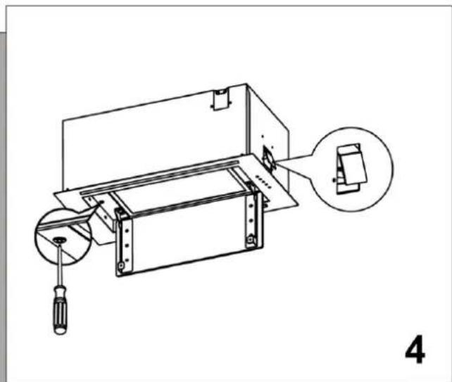
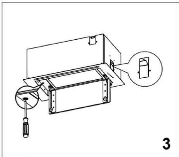
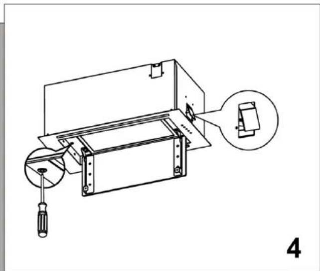
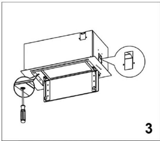
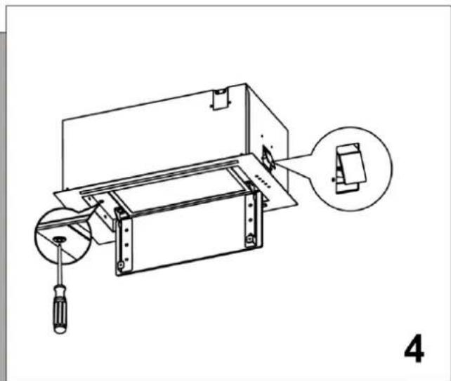
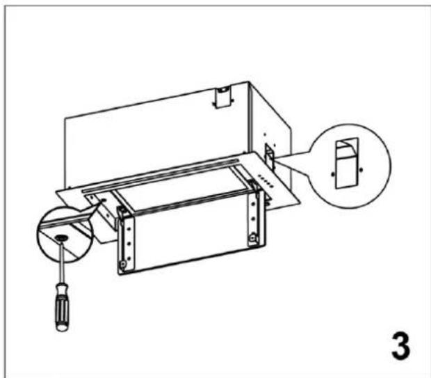
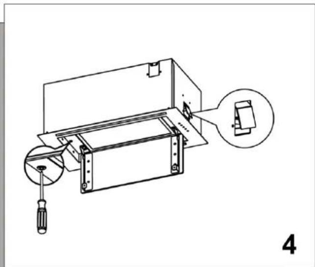
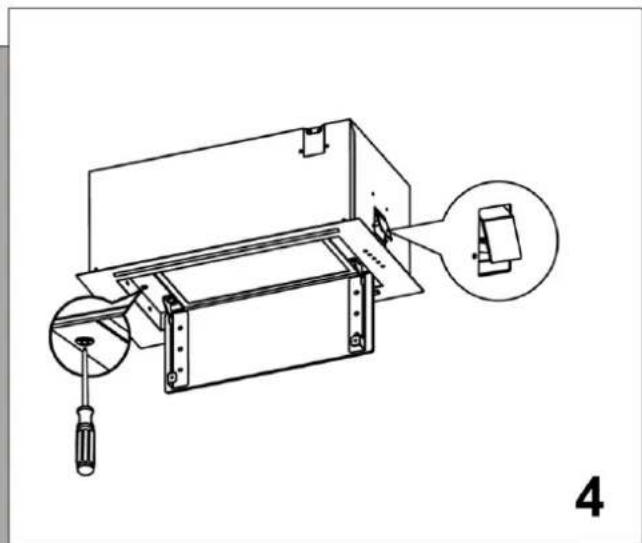
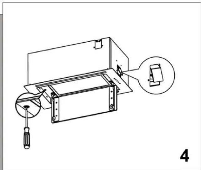
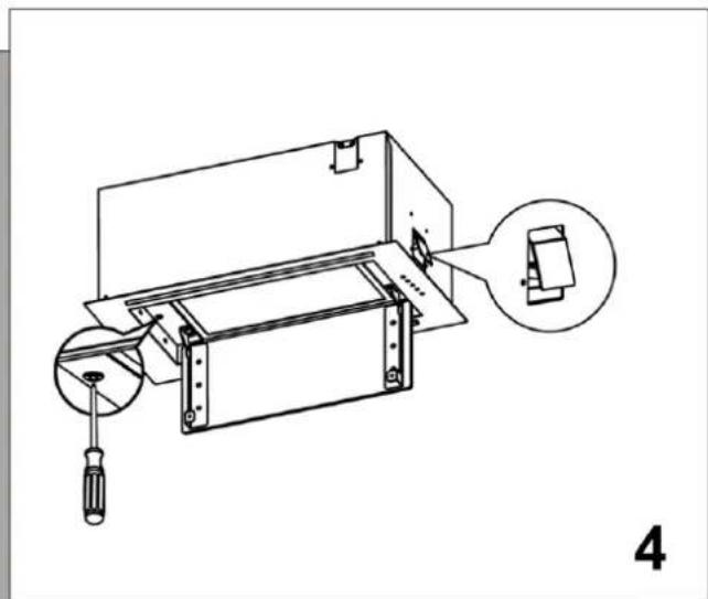
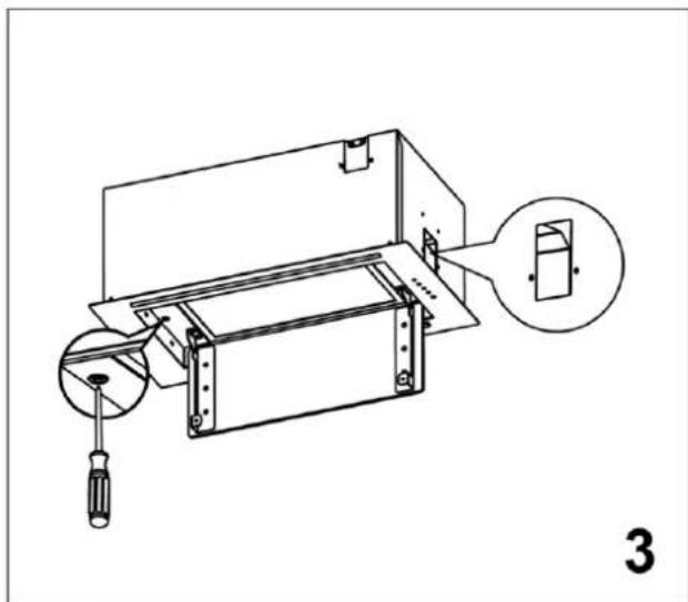
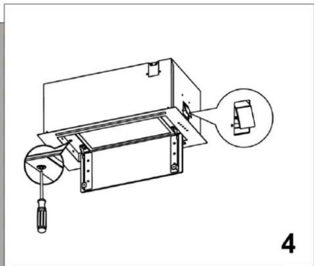
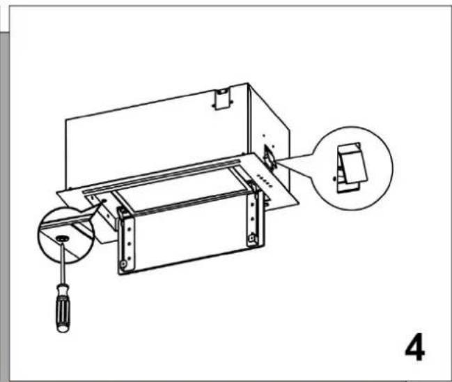
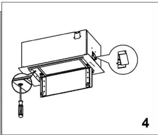
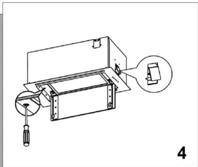
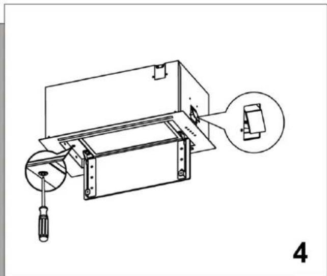
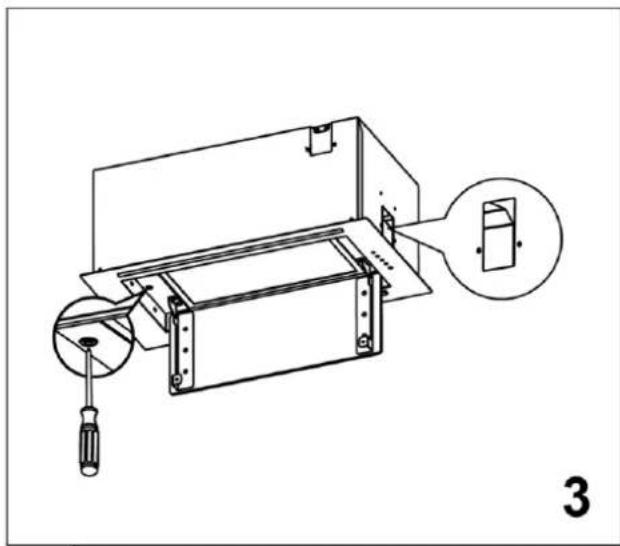
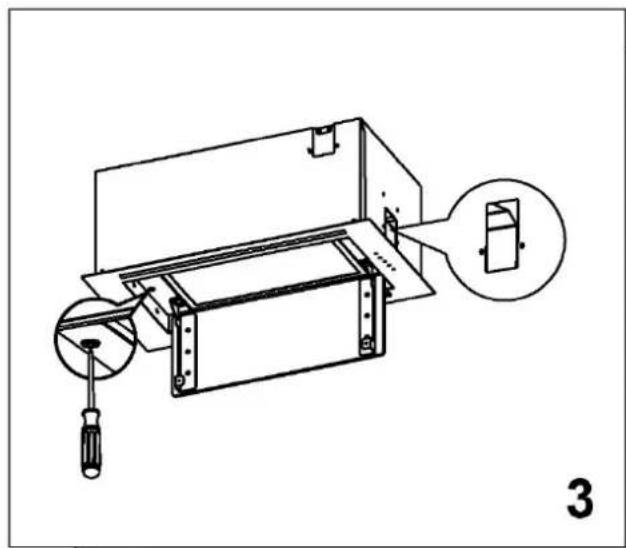
Prior to installation, open the oil baffle and turn the bolt clockwise with a screwdriver to loosen it for easy installation. Loosen the mounting structure tightly fitted to the housing with a screwdriver to facilitate the installation of the entire machine.

InstallationHAIER HAPY72ES6XGG - Information - 4
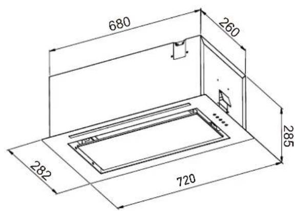
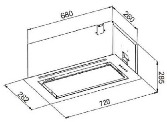
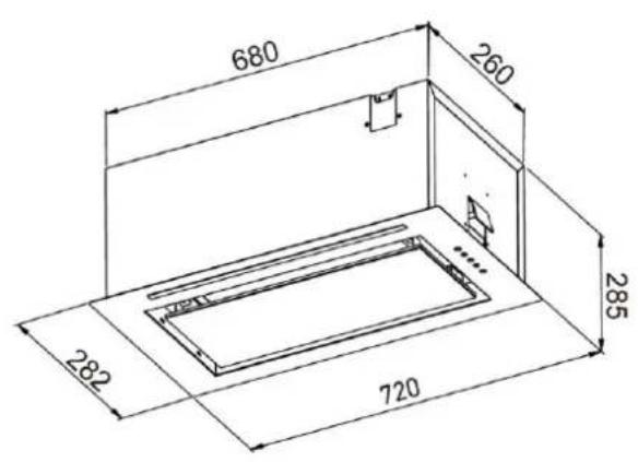
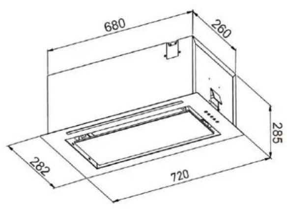
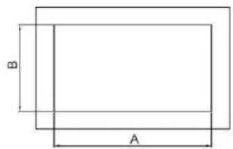
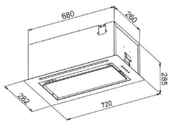
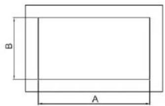
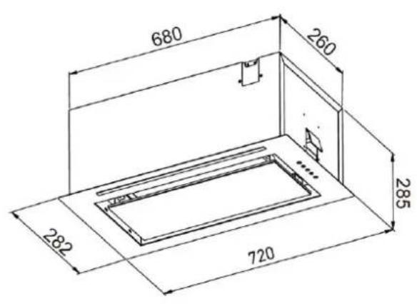
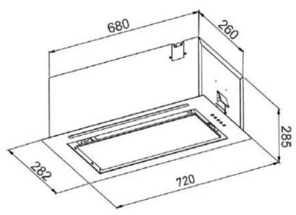
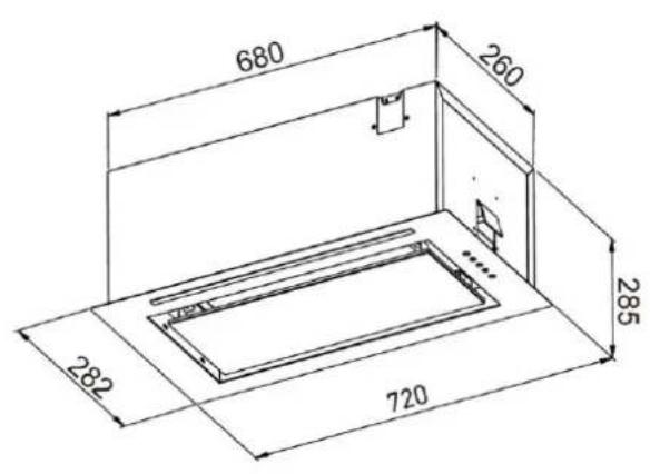
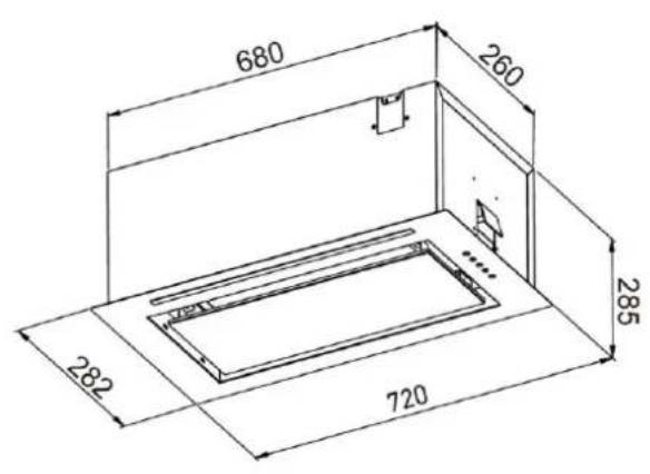
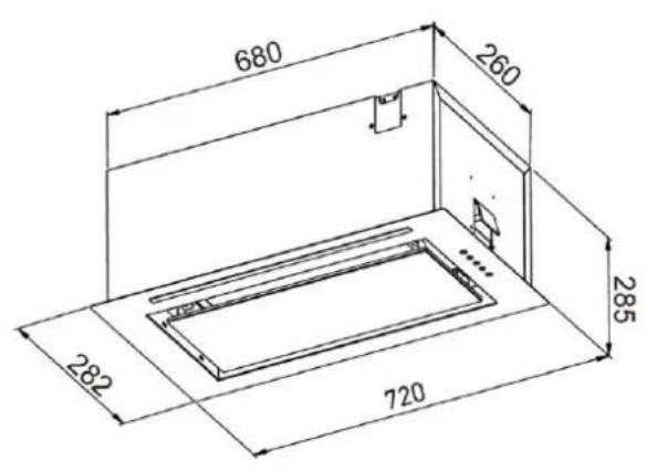
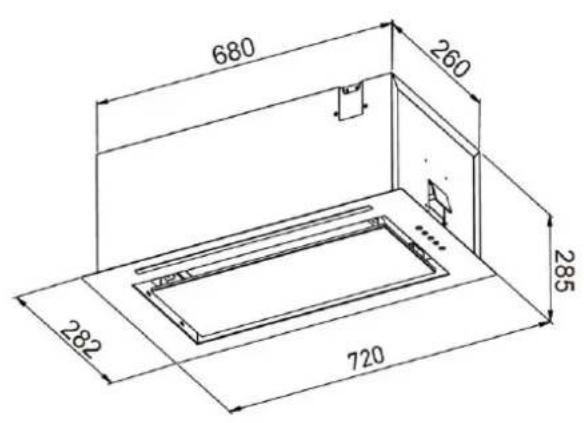
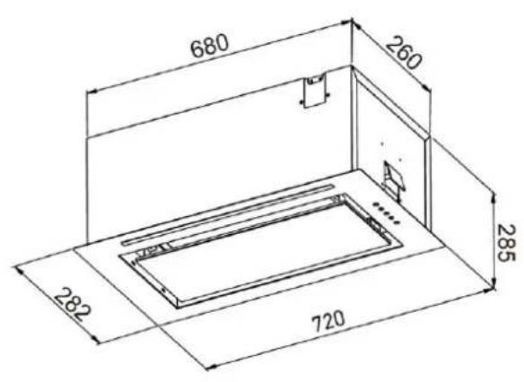
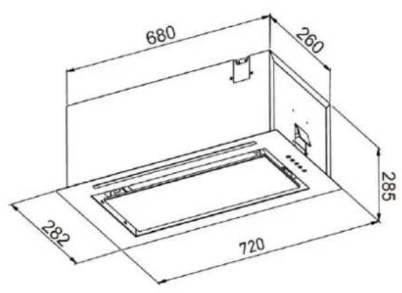
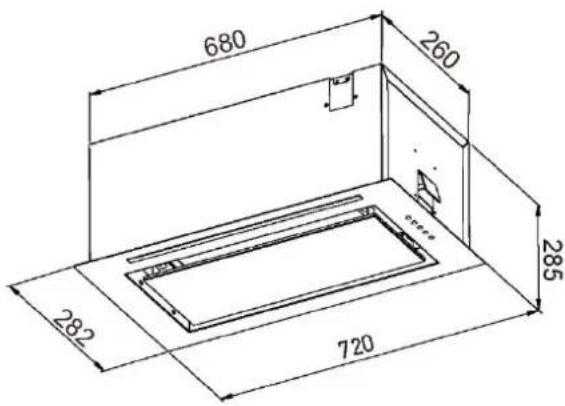
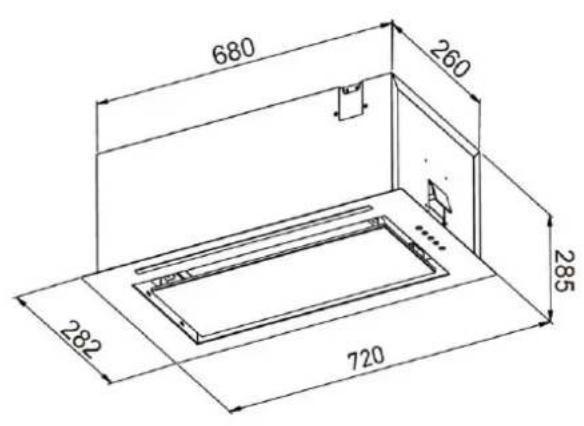
680, 260, 285, 282, 720

5

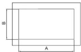
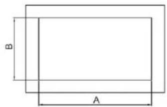
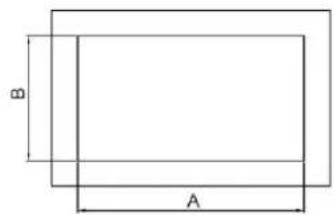
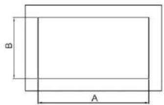
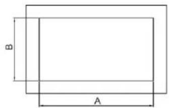
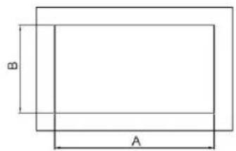
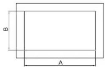
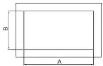
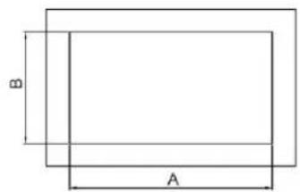
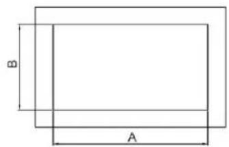
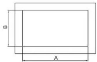
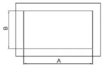
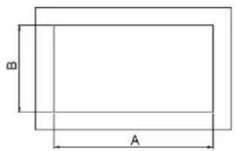
B, A

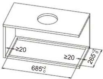
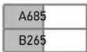
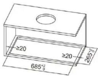
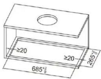
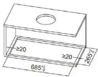
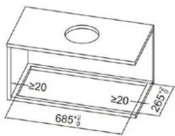
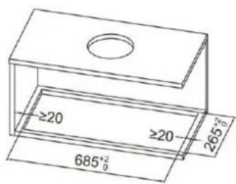
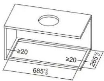
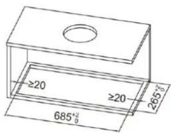
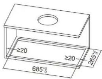
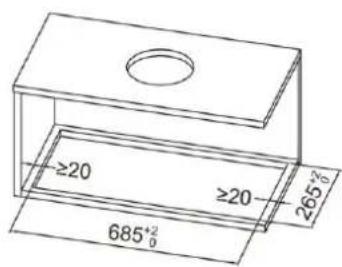
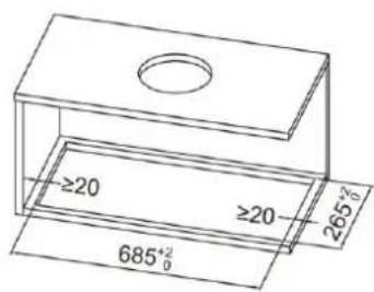
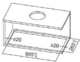
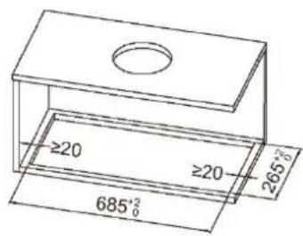
≥20, ≥20, 685°²₀, 265°²₀

6HAIER HAPY72ES6XGG - Information - 8

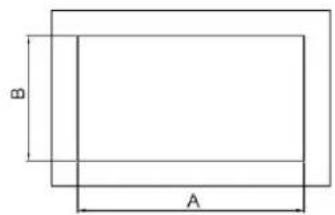
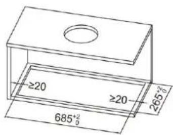
Mark the size of the cut-out according to the dimensions of your bonnet.

InstallationHAIER HAPY72ES6XGG - Information - 9
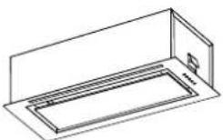
Diagram of a cylindrical device with a circular component mounted on a base, showing a downward arrow indicating rotation (no text or symbols present).

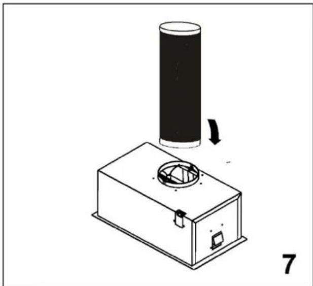
7

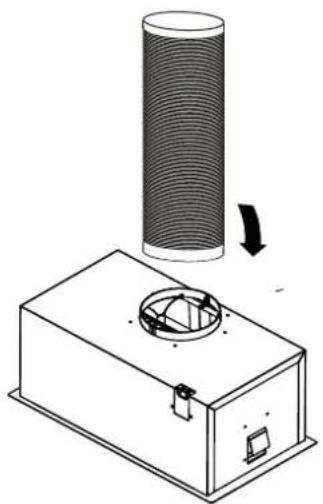
Attach the exhaust pipe to the pipe adapter and place it over the extractor hood as shown.
Technical diagram of a mechanical assembly inside a housing, showing internal components and a close-up inset (no text or labels).

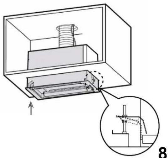
Insert the extractor hood from the bottom up into the cabinet until the locking bracket rests on the bottom shelf.

InstallationHAIER HAPY72ES6XGG - Information - 12
Technical diagram of a mechanical assembly with a screwdriver inserted, showing internal components and a downward arrow indicating motion (no text or symbols present).

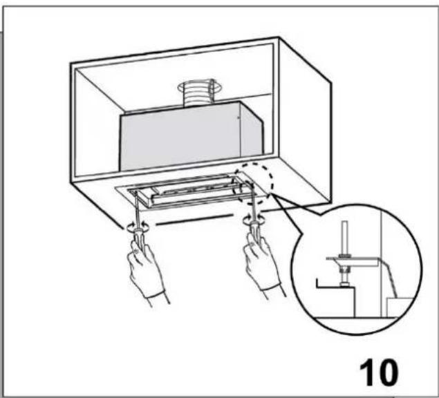
Diagram illustrating a mechanical assembly process with labeled parts and a magnified inset showing a component being inserted.

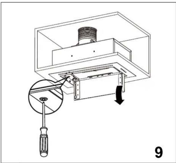
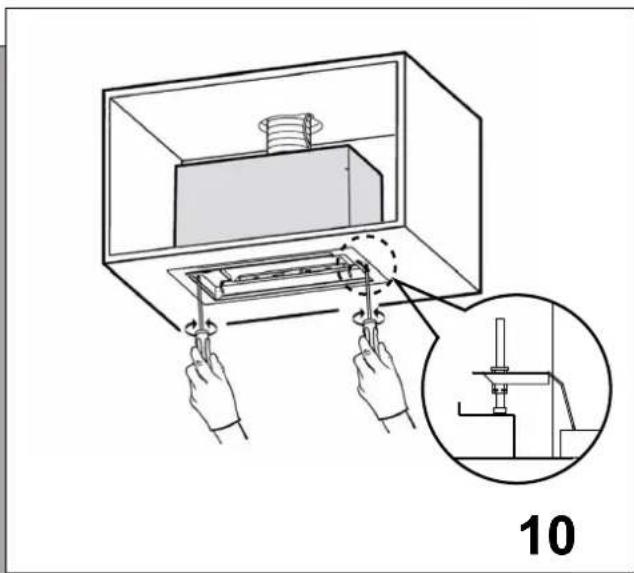
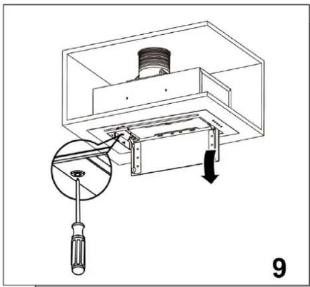
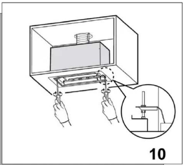
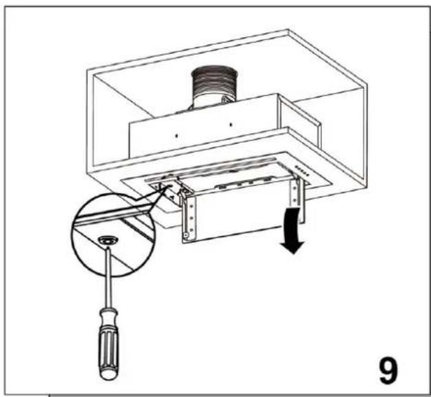
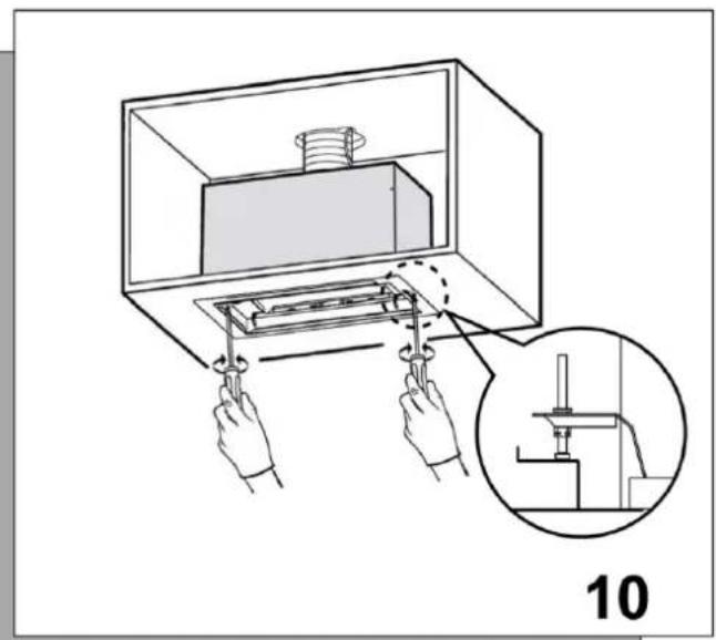
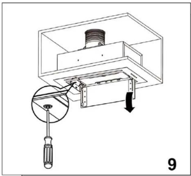
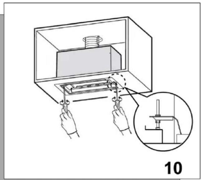
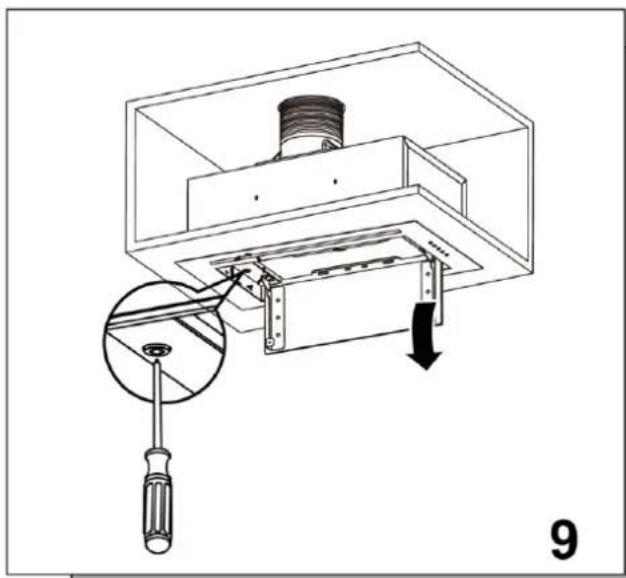
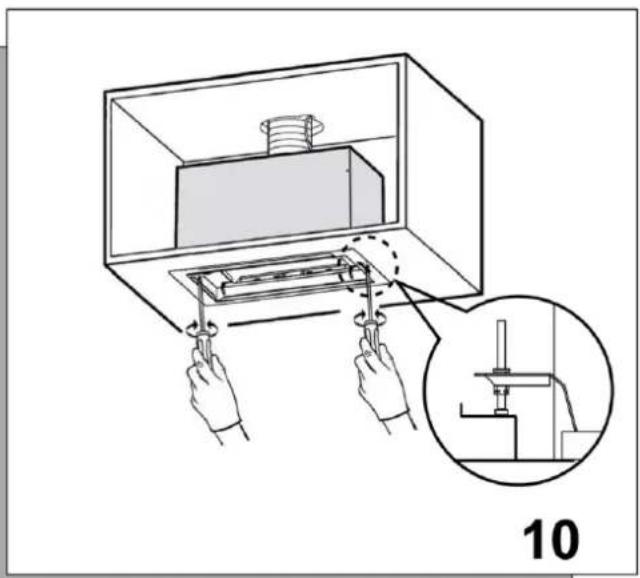
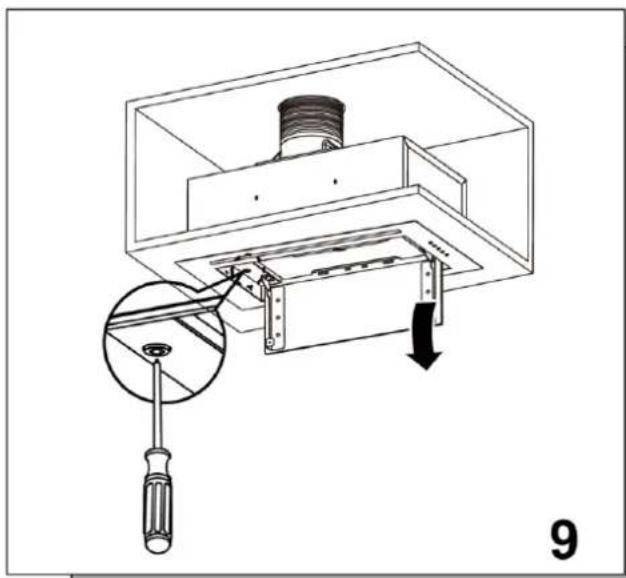
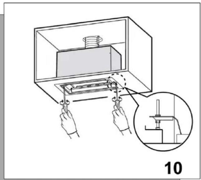
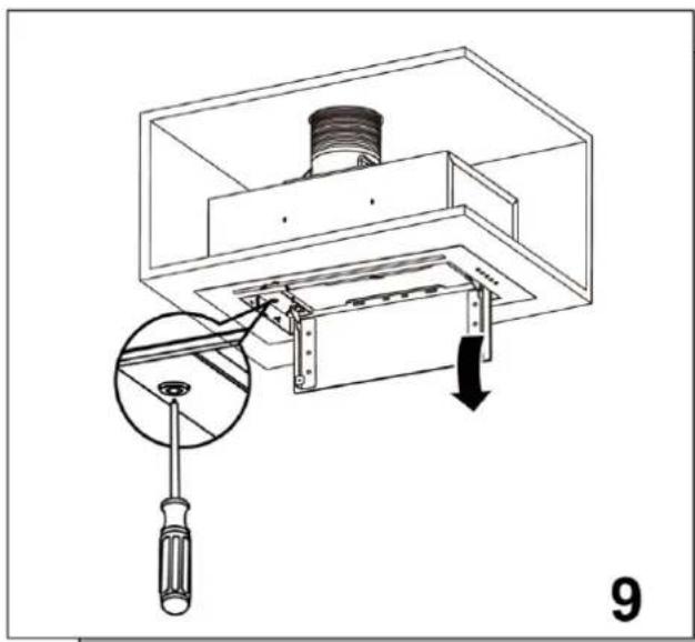
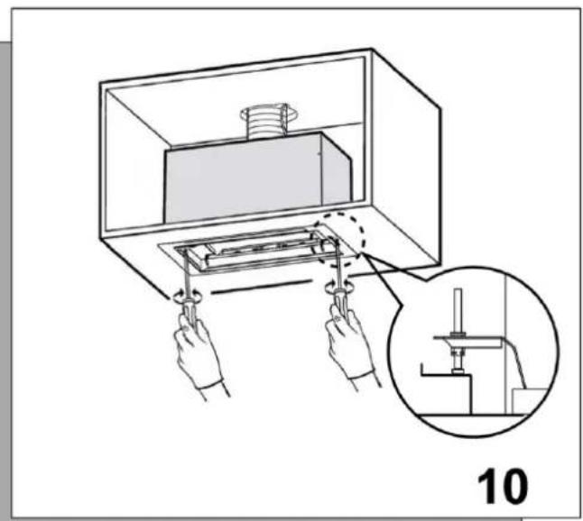
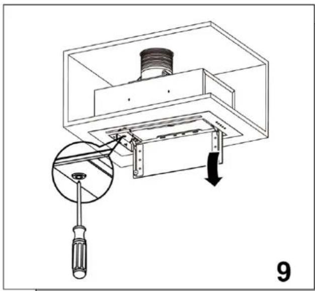
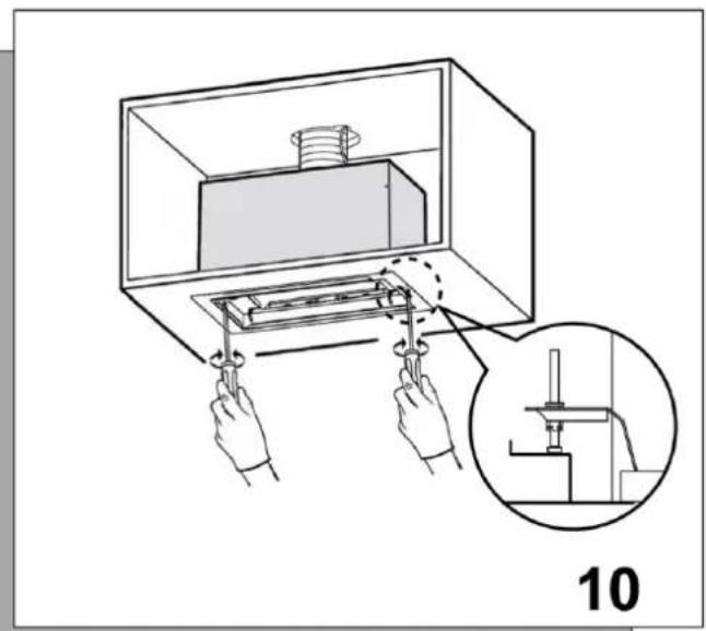
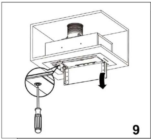
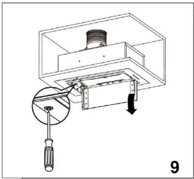
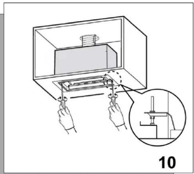
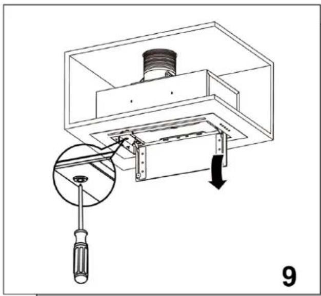
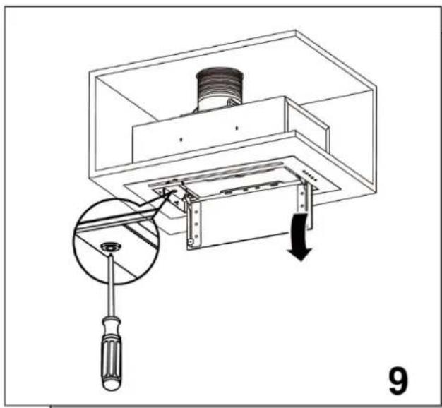
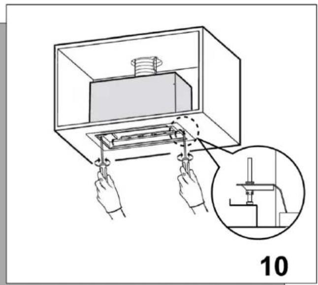
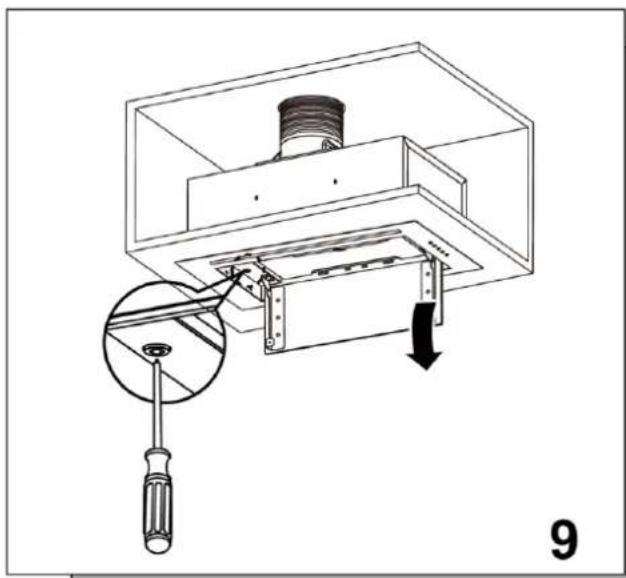
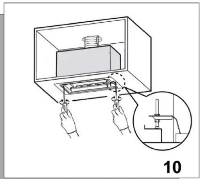
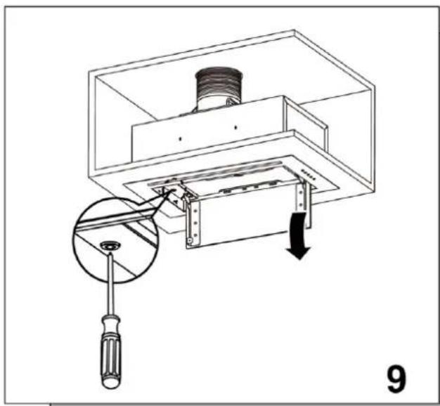
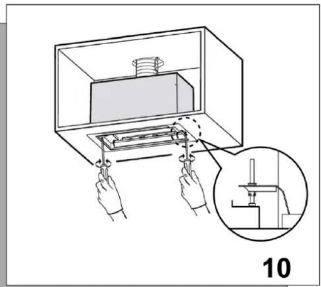
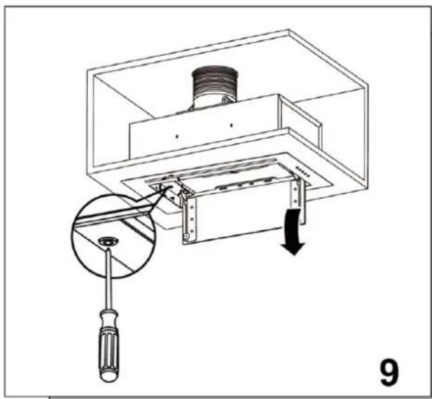
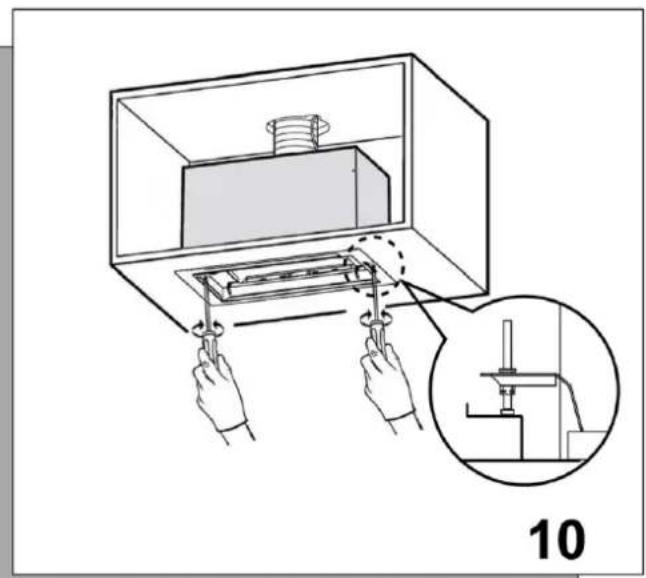
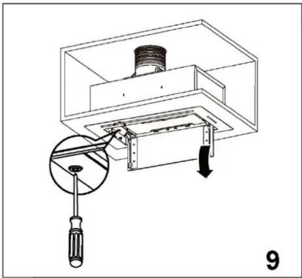
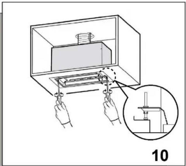
Open the grease filter and remove the two fixing screws with a screwdriver. Lift up until it is fully installed in the bottom of the cabinet. Tighten the screws securing the extractor hood.
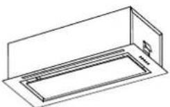
HAIER HAPY72ES6XGG - Information - 15

Controls

① — Low ② Medium ③ —— High (B) —— Boost Light

Speed button:

Press any speed button, the hood will work on this speed, press this speed button again, the hood will stop working.

When press the B button, the hood will work on Boost state for 5 minutes, then go back to Speed 3.

Delay:

Long press the speed button for 2 seconds, enter to delay state on this speed. The default delay time is 15 minutes. When the delay time is up, turn off directly.

Light:

Press Light button to turn on or off the light.
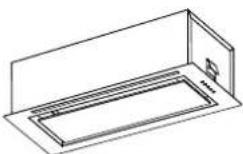
HAIER HAPY72ES6XGG - Light: - 1

Replacement and maintenance

If the supply cord is damaged, it must be replaced by the manufacturer or its service agent or a similarly qualified person in order to avoid a hazard.

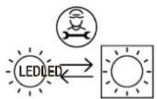
Replacing lamps

The hood is equipped with a lighting system based on LED technology.

The LEDs guarantee an optimum lighting, a duration up to 10 times as long as the traditional lamps and allow to save 90% electrical energy.

In case of malfunction of the illumination system contact the technical service.
HAIER HAPY72ES6XGG - Replacing lamps - 1

Charcoal filterHAIER HAPY72ES6XGG - Replacing lamps - 2

Line drawing of a mechanical device with an open lid and internal compartments, labeled with number 12 (no text or symbols on the diagram itself).

Line drawing of a two-tiered industrial machine or fan unit (no text or symbols visible).

Isometric line drawing of a rectangular mechanical or electrical enclosure with mounting brackets and internal compartments (no text or symbols).

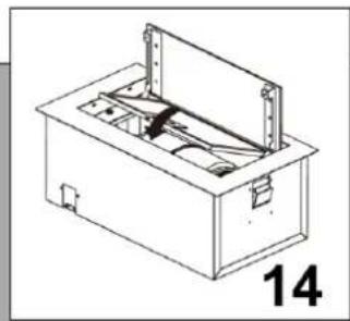
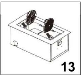
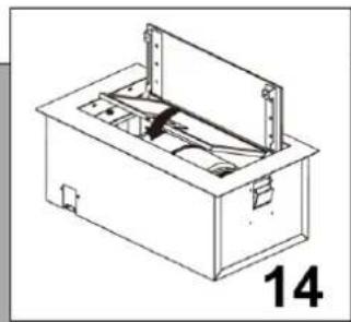
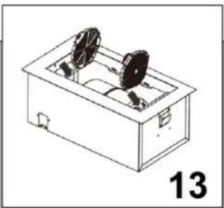
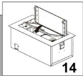
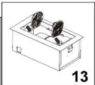
In re-circulating mode, air is vented back into the kitchen through the opening in the cooker hood.

This method is advised if you are not using your hob intensively.

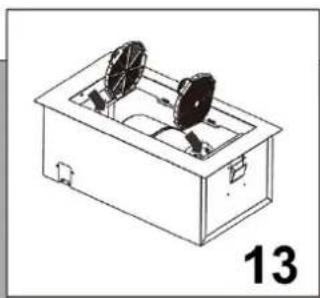
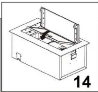
Re-circulated air requires the use of charcoal filters to remove odours.

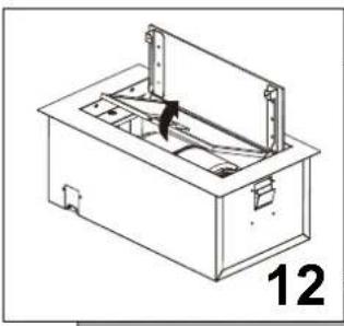
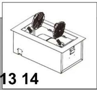
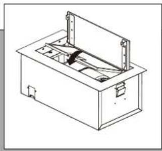
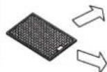
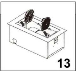
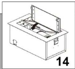
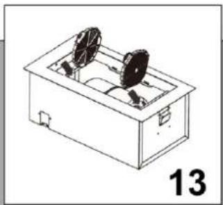
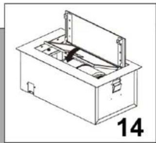
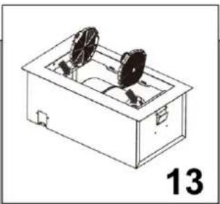
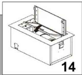
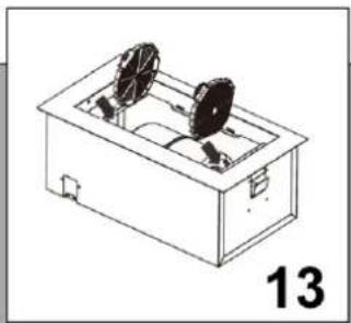
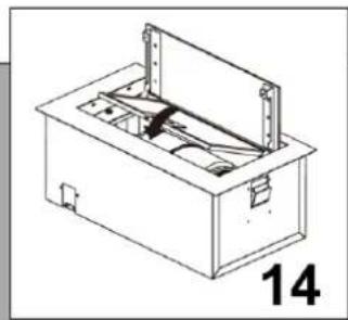
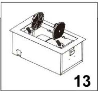
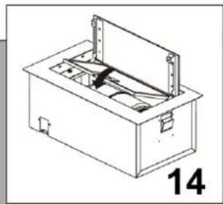
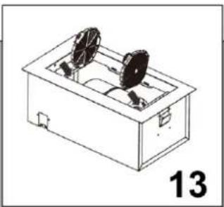
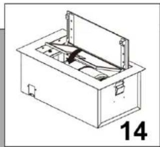
To ensure the best performance from your cooker hood, the charcoal filter should be replaced every 3-6 months, dependent on use.

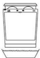
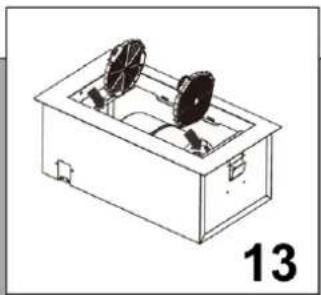
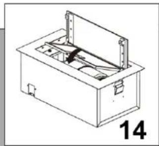
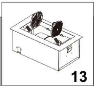
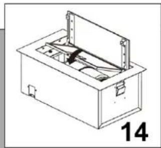
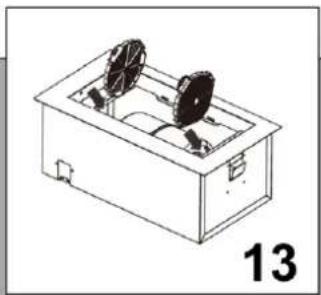
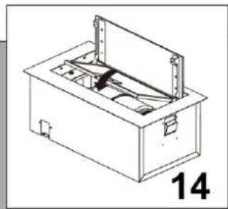
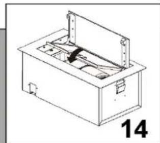
To attach a new charcoal filter, follow the steps below:

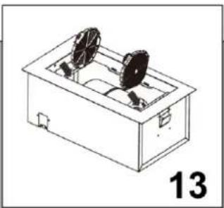
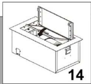
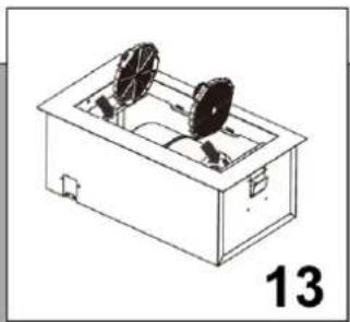
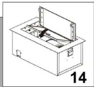
  1. Remove the grease filter.
  2. Place the charcoal filter on the centre of the motor support.
  3. Replace the grease filter.

Information

This charcoal filter is non-washable and must be replaced as required.
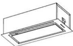
HAIER HAPY72ES6XGG - Information - 1

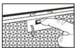
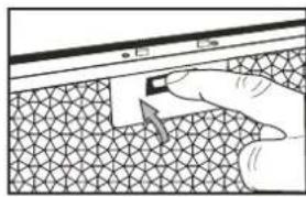
Cleaning grease filters

Hand inserting a small object into a textured surface, no text or symbols visible.

HAIER HAPY72ES6XGG - Cleaning grease filters - 2

HAIER HAPY72ES6XGG - Cleaning grease filters - 3

Hand pressing a button on a textured surface with a small object (no text or symbols visible)

It is recommendable to clean the metallic filter every three months by carrying out the following instructions:

- Remove the metallic filter from the cooker hood and wash it in a solution of water and neutral liquid detergent, leaving to soak

- Rinse thoroughly with warm water and leave to dry.

- The metallic filter may also be washed in the dishwasher.

The metallic filter may alter in color after several washes.

This is not cause for customer complaint nor replacement of metallic filter.

i

Information

There is a

fire risk if

cleaning is

not carried

out in

accordance

with the

instructions.
HAIER HAPY72ES6XGG - Information - 1

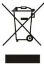
This appliance is labelled in accordance with European Directive 2012/19/EU on Waste Electrical and Electronic Equipment Regulations 2013 regarding electric and electronic appliances (WEEE). The WEEE contain both polluting substances (that can have a negative effect on the environment) and base elements (that can be reused). It is important that the WEEE undergo specific treatments to correctly remove and dispose of the pollutants and recover all the materials. Individuals can play an important role in ensuring that the WEEE do not become an environmental problem; it is essential to follow a few basic rules:

  • the WEEE should not be treated as domestic waste;
  • the WEEE should be taken to dedicated collection areas managed by the town council or a registered company. In many countries, domestic collections may be available for large WEEEs. When you buy a new appliance, the old one can be returned to the vendor who must accept it free of charge as a one-off, as long as the appliance is of an equivalent type and has the same functions as the purchased appliance.

FR RECO

The manufacturer shall decline all responsibility if the foregoing recommendations and instruction regarding installation, maintenance and use are not observed and respected when using the cooker hood.

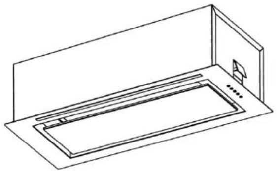
Haier

Hood

Model HAPY72ES6XGG
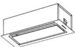
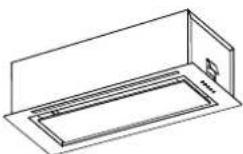
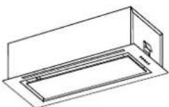
Isometric line drawing of a rectangular kitchen appliance with a lid and base (no text or symbols)

Instruction booklet

Code: 36901992-1 01

Information and advice

Information and advice
Technical line drawing of a mechanical device with a magnified inset showing a component (no text or symbols present)

Installation

680, 260, 285, 282, 720

5

B, A

≥20, ≥20, 685⁺²₀, 265⁺²₀

A685
B265

6

Installation

Technical diagram of a mechanical assembly with a screwdriver inserted, showing internal components and a downward arrow indicating motion (no text or symbols present)

Diagram illustrating a mechanical assembly with labeled parts and a magnified inset showing a component being inserted into a housing.

Controls

Isometric line drawing of a rectangular device with two circular components and a label '13' (no text or symbols on the diagram itself)

Line drawing of a mechanical device with internal components and mounting brackets (no text or symbols)

Operating instructions

Code: 36901992-1 01

Information and advice

Information and advice

Technical line drawing of a mechanical device with a magnified inset showing a component (no text or symbols present)

Installation

680 260 285 282 720

5

B A

≥20 ≥20 685⁺²₀ 265⁺²₀

A685
B265

6

Installation

Technical diagram of a mechanical assembly with a screwdriver inserted, showing internal components and a downward arrow indicating motion (no text or symbols present)

Diagram of a mechanical device with hands operating it, showing internal components and a magnified inset (no text or symbols)

Controls

Line drawing of a rectangular device with two fans and a lid, labeled '13' (no text or symbols on the diagram itself)

Line drawing of a mechanical device with internal components and mounting brackets (no text or symbols)

Operating instructions

Installation

Technical line drawing of a mechanical device with a magnified inset showing a component (no text or symbols)

Technical line drawing of a mechanical device with a magnified inset showing a component (no text or symbols present)

Installation

680 260 285 282 720

5

B A

≥20 ≥20 685⁺²₀ 265⁺²₀

A685
B265

6

Installation

Technical diagram of a mechanical assembly with a screwdriver inserted, showing internal components and a downward arrow indicating motion (no text or symbols present)

Diagram of a mechanical device with hands operating it, showing internal components and a magnified inset (no text or symbols)

Control panel

① — Low ② — Medium ③ — High (B) —— Boost lighting

Isometric line drawing of a rectangular device with two circular components and a label '13' (no text or symbols on the diagram itself)

Line drawing of a mechanical device with open lid and internal compartments, labeled '14' (no text or symbols on the diagram itself)

Installation

Technical line drawing of a mechanical device with a magnified inset showing a component (no text or symbols)

Technical line drawing of a mechanical device with a magnified inset showing a component (no text or symbols present)

Installation

680, 260, 285, 282, 720

5

B, A

≥20, ≥20, 685⁺²₀, 265⁺²₀

A685
B265

6

Installation

Technical diagram of a mechanical assembly with a screwdriver inserted, showing internal components and a downward arrow indicating motion (no text or symbols present)

Diagram illustrating a mechanical assembly with labeled parts and a magnified inset showing a component being inserted into a housing.

Controls

① — Low ② — Medium ③ — High Light

B Maximum power

Speed button:

Line drawing of a rectangular device with two fans and a lid, labeled '13'.

Line drawing of a mechanical device with internal components and mounting brackets.

Diagram showing a hand interacting with a textured surface and a small object.

Code: 36901992-1 01

Information and advice

Information and advice

Installation
Technical line drawing of a mechanical device with a magnified inset showing a component.

Technical line drawing of a mechanical device with a magnified inset showing a component.

Installation

680, 260, 285, 282, 720

5

B, A

≥20, ≥20, 685⁺²₀, 265⁺²₀

A685
B265

6

Installation

Technical diagram of a mechanical assembly with a screwdriver inserted, showing internal components and a downward arrow indicating motion (no text or symbols present)

Diagram of a mechanical device with hands operating it, showing internal components and a magnified inset (no text or symbols)

Controls

① — Low ② —— Medium ③ — High (B) — Boost Light

Speed button:

Line drawing of a rectangular device with two fans and a lid, labeled '13' (no text or symbols on the diagram itself)

Line drawing of a mechanical device with internal components and mounting brackets (no text or symbols)

HAIER HAPY72ES6XGG - Speed button: - 3

Information

User manual

Code: 36901992-1 01

Installation

Technical line drawing of a mechanical device with a magnified inset showing a component (no text or symbols)

Technical line drawing of a mechanical device with a magnified inset showing a component (no text or symbols present)

Installation

680 260 285 282 720

5

B A

≥20 ≥20 685⁺²₀ 265⁺²₀

A685
B265

6

Installation

Technical diagram of a mechanical assembly with a screwdriver inserted, showing internal components and a downward arrow indicating motion (no text or symbols present)

Diagram of a mechanical device with hands operating it, showing internal components and a magnified inset (no text or symbols)

Controls

Isometric line drawing of a rectangular device with two circular components and a label '13' (no text or symbols on the diagram itself)

Line drawing of a mechanical device with open lid and internal compartments, labeled '14' (no text or symbols on the diagram itself)

User manual

Code: 36901992-1 01

Installation

Technical line drawing of a mechanical device with a magnified inset showing a component (no text or symbols)

Technical line drawing of a mechanical device with a magnified inset showing a component (no text or symbols present)

Installation

680, 260, 285, 282, 720

5

B, A

≥20, ≥20, 685⁺²₀, 265⁺²₀

A685
B265

6

Installation

Technical diagram of a mechanical assembly with a screwdriver inserted, showing internal components and a downward arrow indicating motion (no text or symbols present)

Diagram of a mechanical device with hands operating it, showing internal components and a magnified inset (no text or symbols)

Line drawing of a rectangular device with two fans and a lid, labeled '13' (no text or symbols on the diagram itself)

Line drawing of a mechanical device with internal components and mounting brackets (no text or symbols)

User manual

Code: 36901992-1 01

Installation

Technical line drawing of a mechanical device with a magnified inset showing a component (no text or symbols)

Technical line drawing of a mechanical device with a magnified inset showing a component (no text or symbols present)

Installation

680 260 285 282 720

5

B A

≥20 ≥20 685⁺²₀ 265⁺²₀

A685
B265

6

Installation

Technical diagram of a mechanical assembly with a screwdriver inserted, showing internal components and a downward arrow indicating motion (no text or symbols present)

Diagram of a mechanical device with hands operating it, showing internal components and a magnified inset (no text or symbols)

Controls

Isometric line drawing of a rectangular device with two circular components and a label '13' (no text or symbols on the diagram itself)

Line drawing of a mechanical device with open lid and internal compartments, labeled '14' (no text or symbols on the diagram itself)

Diagram showing a hand interacting with a textured surface and a small object, no text or symbols present

Instruction manual

Code: 36901992-1 01

Installation

Technical line drawing of a mechanical device with a magnified inset showing a component (no text or symbols)

Technical line drawing of a mechanical device with a magnified inset showing a component (no text or symbols present)

Installation

680, 260, 285, 282, 720

5

B, A

≥20, ≥20, 685⁺²₀, 265⁺²₀

A685
B265

6

Installation

Technical diagram of a mechanical assembly with a screwdriver inserted, showing internal components and a downward arrow indicating motion (no text or symbols present)

Diagram of a mechanical device with hands operating it, showing internal components and a magnified inset (no text or symbols)

Controls

Isometric line drawing of a rectangular device with two circular components and a label '13' (no text or symbols on the diagram itself)

Line drawing of a mechanical device with open lid and internal compartments, labeled '14' (no text or symbols on the diagram itself)

HAIER HAPY72ES6XGG - Controls - 3

Information

This charcoal

filter is not

washable and

must be

replaced when

necessary.

Code: 36901992-1 01

Installation

Technical line drawing of a mechanical device with a magnified inset showing a component (no text or symbols)

Technical line drawing of a mechanical device with a magnified inset showing a component (no text or symbols present)

Installation

680 260 285 282 720

5

B A

≥20 ≥20 685⁺²₀ 265⁺²₀

A685
B265

6

Installation

Technical diagram of a mechanical assembly with a screwdriver inserted, showing internal components and a downward arrow indicating motion (no text or symbols present)

Diagram of a mechanical device with hands operating it, showing internal components and a magnified inset (no text or symbols)

Isometric line drawing of a rectangular device with two circular components and a label '13' (no text or symbols on the diagram itself)

Line drawing of a mechanical device with open lid and internal compartments, labeled '14' (no text or symbols on the diagram itself)

Code: 36901992-1 01

Information and advice

Information and advice
Installation
Technical line drawing of a mechanical device with a magnified inset showing a component (no text or symbols).

Technical line drawing of a mechanical device with a magnified inset showing a component (no text or symbols).

Installation

680, 260, 285, 282, 720

5

B, A

≥20, ≥20, 685⁺²₀, 265⁺²₀

A685
B265

6

Installation

Technical diagram of a mechanical assembly with a screwdriver inserted, showing internal components and a downward arrow indicating motion (no text or symbols).

Diagram of a mechanical device with hands operating it, showing internal components and a magnified inset (no text or symbols).

Isometric line drawing of a rectangular device with two circular components and a label '13' (no text or symbols on the diagram itself).

Line drawing of a mechanical device with open lid and internal compartments, labeled '14' (no text or symbols on the diagram itself).

Instruction manual

Code: 36901992-1 01

Technical line drawing of a mechanical device with a magnified inset showing a component (no text or symbols present)

Installation

680, 260, 285, 282, 720

5

B, A

≥20, ≥20, 685⁺²₀, 265⁺²₀

A685
B265

6

Installation

Technical diagram of a mechanical assembly with a screwdriver inserted, showing internal components and a downward arrow indicating motion (no text or symbols present)

Diagram of a mechanical device with hands operating it, showing internal components and a magnified inset (no text or symbols)

Controls

Line drawing of a rectangular device with two fans and a lid, labeled '13' (no text or symbols on the diagram itself)

Line drawing of a mechanical device with internal components and mounting brackets (no text or symbols)

i

Installation

Technical line drawing of a mechanical device with a magnified inset showing a component (no text or symbols present)

Technical line drawing of a mechanical device with a magnified inset showing a component (no text or symbols present)

Installation

680, 260, 285, 282, 720

5

B, A

≥20 ≥20 685⁺²⁰ 265⁺²⁰

A685
B265

6

Installation

Technical diagram of a mechanical assembly with a screwdriver inserted, showing internal components and a downward arrow indicating motion (no text or symbols present)

Diagram of a mechanical device with hands operating it, showing internal components and a magnified inset (no text or symbols)

Controls

Isometric line drawing of a rectangular device with two circular components and a label '13' (no text or symbols on the diagram itself)

Line drawing of a mechanical device with open lid and internal compartments, labeled '14' (no text or symbols on the diagram itself)

and

Code: 36901992-1 01

Information and advice

Information and advice

Installation
Technical line drawing of a mechanical device with a magnified inset showing a component (no text or symbols).

Technical line drawing of a mechanical device with a magnified inset showing a component (no text or symbols present).

Installation

680 260 285 282 720

5

B A

≥20 ≥20 685⁺²₀ 265⁺²₀

A685
B265

6

Insert the extractor from bottom to top into the cabinet until the locking bracket rests on the bottom shelf.
Isometric line drawing of a rectangular frame with a recessed top and side gap (no text or symbols).

Installation

Technical diagram of a mechanical assembly with a screwdriver inserted, showing internal components and a downward arrow indicating motion (no text or symbols present).

Diagram of a mechanical device with hands operating it, showing internal components and a magnified inset (no text or symbols).

Line drawing of a rectangular device with two fans and a lid, labeled '13' (no text or symbols on the diagram itself).

Line drawing of a mechanical device with internal components and mounting brackets (no text or symbols).

Instruction manual

Technical line drawing of a mechanical device with a magnified inset showing a component (no text or symbols present)

Diagram illustrating a mechanical assembly or installation procedure with labeled components and a magnified inset showing a close-up view.

Line drawing of a rectangular device with two circular components and a label '13' (no text or symbols on the diagram itself)

Line drawing of a mechanical device with a rectangular housing and mounting brackets (no text or symbols)

Instruction manual

Kwō:36901992-1 01

Installation
Technical line drawing of a mechanical device with a pulley and attached component, labeled '3' (no text or symbols on the diagram itself)

Technical line drawing of a mechanical device with a magnified inset showing a component (no text or symbols)

Installation

680 260 285 282 720

5

B A

≥20 ≥20 685°²₀ 265°²₀

A685
B265

6

Installation

Diagram of a cylindrical device mounted on a base with a circular component, labeled '7' (no text or symbols on the diagram itself)

Installation

Technical diagram of a mechanical assembly with a screwdriver inserted, showing internal components and a downward arrow indicating motion (no text or symbols present)

Diagram illustrating a mechanical assembly with labeled parts and a magnified inset showing a component detail.

Controls

Line drawing of a rectangular electronic device with two circular components and a label '13' (no text or symbols on the device itself)

Technical line drawing of a rectangular mechanical or electrical enclosure with internal components and mounting brackets (no text or symbols)

Manual assistant
Powered by Anthropic
Waiting for your message
Product information

Brand : HAIER

Model : HAPY72ES6XGG

Category : Range hood