
HABT9CBS6XBSLC - Basket HAIER - Free user manual and instructions
Find the device manual for free HABT9CBS6XBSLC HAIER in PDF.

| Product type | Cooker hood |
| Brand | Haier |
| Model | HABT9CBS6XBSLC |
| Installation | Built-in into a cabinet |
| Minimum installation height | 650 mm above heating elements and burners (max 750 mm) |
| Speed functions | Low (T2), Medium (T3), High (T4), Intensive (T5) - automatic return to medium speed after 5 min, then automatic stop after 10 min |
| Lighting | LED with color adjustment (simultaneous press T1 and T6) |
| Automatic sensor | Yes (button T7) - smoke detection, starts at medium speed |
| Metal filter | Dishwasher or hand wash with neutral detergent, every 3 months |
| Charcoal filter | Internal cycle mode (recirculation) - requires installation |
| Lamp replacement | Integrated LED, intervention by technical service |
| Power supply | See rating label on the device (voltage, frequency, power) |
| Usage | Indoor and domestic use only, max 4 burners |
| Safety | Do not touch the bulb 30 min after use; do not flambé under the hood; disconnect before maintenance; follow air extraction instructions |
| Maintenance | Regular cleaning of filters to avoid fire risk |
| Compliance | WEEE Directive 2012/19/EU |
Frequently Asked Questions - HABT9CBS6XBSLC HAIER
User questions about HABT9CBS6XBSLC HAIER
0 question about this device. Answer the ones you know or ask your own.
Ask a new question about this device
Download the instructions for your Basket in PDF format for free! Find your manual HABT9CBS6XBSLC - HAIER and take your electronic device back in hand. On this page are published all the documents necessary for the use of your device. HABT9CBS6XBSLC by HAIER.
USER MANUAL HABT9CBS6XBSLC HAIER
natural_image
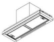
Technical line drawing of a mechanical assembly with no visible text or symbolsInstruction Book

Information and advice
CAUTION:Accessible parts may become hot when used with cooking appliances.
In certain circumstances electrical appliance may be a danger hazard.
A) There must be adequate ventilation of the room when the cooker hood is used at the same time as appliances burning gas or other fuels.
B) Do not check the status of the filters while the cooker hood is operating.
C) Do not touch the light bulb within half an hour after appliance has been use.
D) Do not light a flame under the cooker hood.
E) Avoid opening gasometer when there is no pan on the stove, as it is damaging for the filters and a fire hazard.
F) Constantly check food frying to avoid overheated oil splashing and becoming a fire hazard.
G) Disconnect the electrical plug prior to any maintenance.
H) Regulations concerning the discharge of air have to be fulfilled.
I) When the range hood and appliances supplied with energy Other than electricity are simultaneously in operation. The negative pressure in the room must not exceed 4 Pa ( 4 × 10^-5 bar)

Information and advice
CAUTION:Accessible parts may become hot when used with cooking appliances.
J) If the supply cord is damaged, it must be replaced by the manufacturer, its service agent or similarly qualified persons in order to avoid a hazard.
K) This appliance can be used by children aged from 8 years and above and persons with reduced physical, sensory or mental capabilities or lack of experience and knowledge if they have been given supervision or instruction concerning use of the appliance in a safe way and understand the hazards involved. Children shall not play with the appliance. Cleaning and user maintenance shall not be made by children unless they are older than 8 and supervised.
L) The range hood is intended to be installed over a hob having no more than four hob elements.
M) Indoor use and household use only
N) When the appliance is not in use and before cleaning, unplug the appliance from the outlet.
O) Attention! Observe the warning in the instruction sheet concerning the operation of the appliance when air is discharged from the room
P) There is a fire risk if cleaning is not carried out in accordance with the instructions.

Information and advice
CAUTION:Accessible parts may become hot when used with cooking appliances.
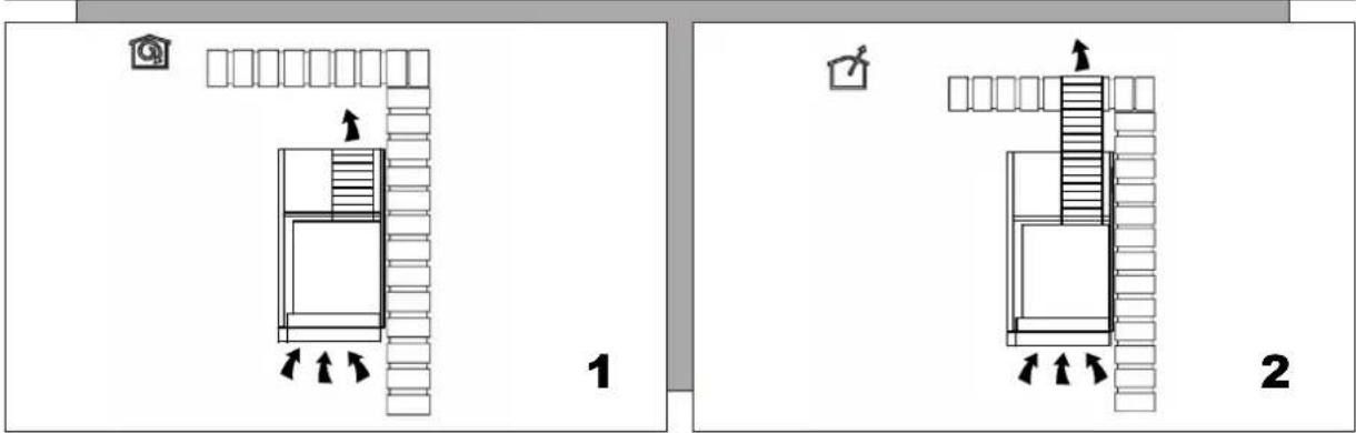
Q) The air must not be discharged into a flue that is used for exhausting fumes from appliances burning gas or other fuels (not applicable to appliances that only discharge the air back into the room.
I) Children should be supervised to ensure that they do not play with the appliance.
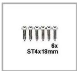
S) Warning: Failure to install the screws or fixing device in accordance with these instructions may result in electrical hazards.
T) The installation height of hood shall not be less than 65cm.
U) The filter screen must be cleaned regularly, otherwise there is a danger of fire.
V) The installation must be carried out according to the screws and positions required by the instructions, which will easily damage the connecting wires.
Information and advice

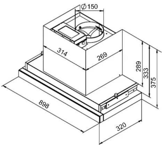
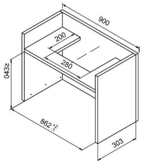
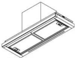
Cooker Hood Dimensions
3

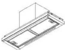
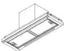
Installation
Suitable for cabinet installation Suitable for cabinet installation
4
5

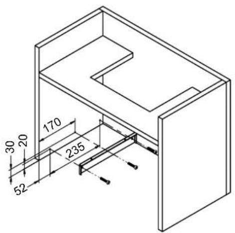
Installation
natural_image
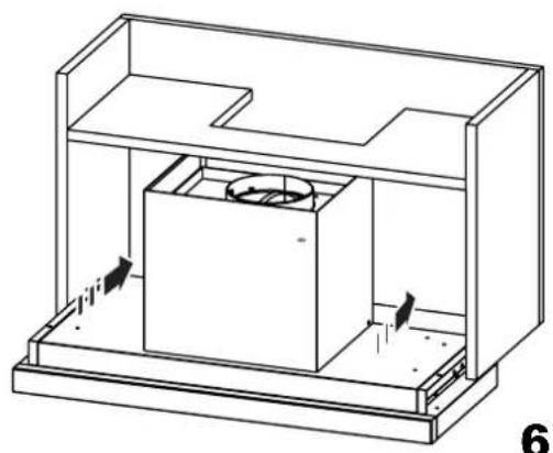
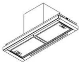
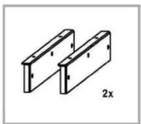
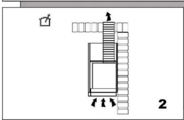
Technical line drawing of a mechanical assembly with internal components and directional arrows (no text or symbols)Align the sides of the machine with the support brackets on the cabinet and push the entire machine into the cabinet.
natural_image
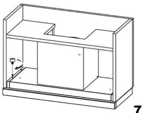
Line drawing of a 3D rectangular enclosure with internal compartments and a small cylindrical object inside (no text or symbols)Once the machine is placed, secure the bezel with screws.
natural_image
Isometric line drawing of a mechanical or architectural component with no visible text, numbers, or symbols.Information and advice
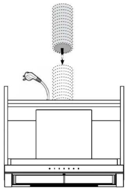
Check the voltage, frequency and power of the rating label on the body.
8
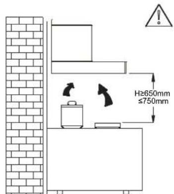
We recommend that after installation the bottom of the hood should be no less than 650mm and no more than 750mm above the stove's heating elements and burners.
i
Information
The air must not be discharged into a flue that is used for exhausting fumes from appliances burning gas or other fuels (not applicable to appliances that only discharge the air back into the room)

natural_image
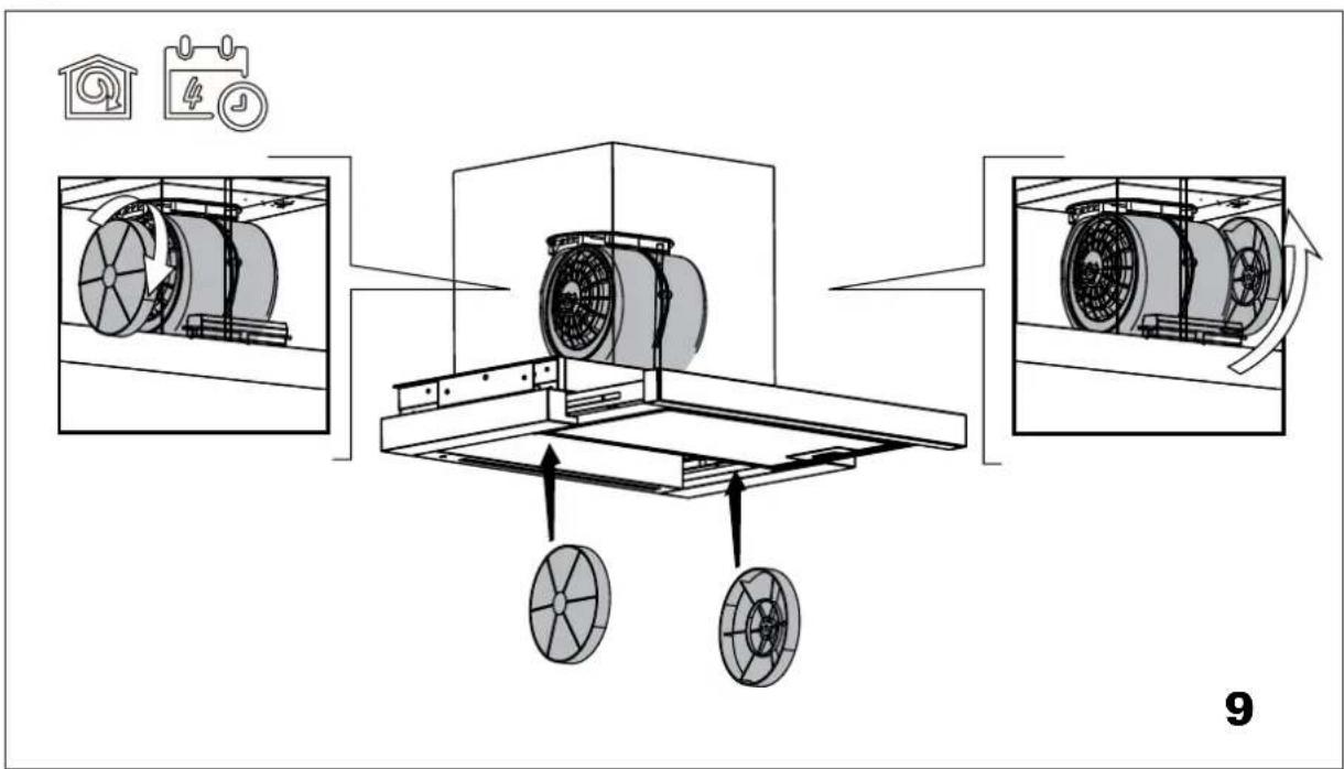
Isometric line drawing of a rectangular frame with internal compartments and mounting holes (no text or symbols)Charcoal filter (Inner-cycle mode)
natural_image
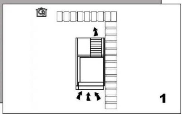
Isometric line drawing of a rectangular frame with internal compartments and mounting holes (no text or symbols)Installation of hoses (outer row mode)

natural_image
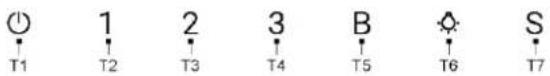
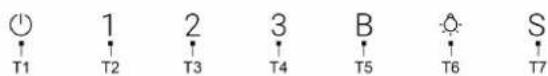
Diagram of a mechanical setup with a cylindrical component being inserted into a base, connected to an electric plug (no text or symbols present)Controls
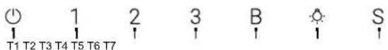
T1 = ON/OFF key
T2 = Speed selection key (extraction power) low.
T3 = Speed selection key (extraction power) medium.
T4 = Speed selection key (extraction power) high.
T5 = Speed selection key (suction power) intensive, after working 5 minutes it switches to the medium speed. Medium speed continue to delay for 10 minutes, and power off automatically.
T6 = Light on/off key
Press "T6" key to turn on or off the light.
Note: At the same time, press "T1" and "T6" to adjust the light color.
T7 = Sensor key
Press "T7" key, the key will flash for 5 minutes.
The hood will switch on at the Middle speed based on the fumes detected by the sensor the hood is equipped with.
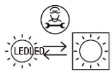
When the front panel is open, all functions are available.
When the front panel is closed, the only operations possible are turning the light on/off (T6) and adjusting the light's color (press T1 and T6 at the same time).
i
Information
Do not touch the light bulb within half an hour after appliance use.
The lamp shall not be covered with thermal insulation or other material.
Replacement and maintenance
If the supply cord is damaged, it must be replaced by the manufacturer or its service agent or a similarly qualified person in order to avoid a hazard.
Replacing lamps
The hood is equipped with a lighting system based on LED technology.
The LEDs guarantee an optimum lighting, a duration up to 10 times as long as the traditional lamps and allow to save 90% electrical energy.
In case of malfunction of the illumination system contact the technical service.
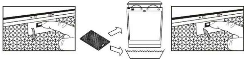
Cleaning filters
flowchart
graph LR
    A["Car Washing"] --> B["Receiving Top Cover"]
    B --> C["Receiving Bottom Cover"]
    C --> D["Final Finishing"]
- It is recommendable to clean the metallic filter every three months by carrying out the following instructions:
-Remove the metallic filter from the cooker hood and wash it in a solution of water and neutral liquid detergent, leaving to soak
-Rinse thoroughly with warm water and leave to dry.
-The metallic filter may also be washed in the dishwasher.
The metallic filter may alter in color after several washes.
This is not cause for customer complaint nor replacement of metallic filter.
i
Information
There is a fire risk if cleaning is not carried out in accordance with the instructions.
This appliance is labelled in accordance with European Directive 2012/19/EU on Waste Electrical and Electronic Equipment Regulations 2013 regarding electric and electronic appliances (WEEE). The WEEE contain both polluting substances (that can have a negative effect on the environment) and base elements (that can be reused). It is important that the WEEE undergo specific treatments to correctly remove and dispose of the pollutants and recover all the materials. Individuals can play an important role in ensuring that the WEEE do not become an environmental problem; it is essential to follow a few basic rules:
- the WEEE should not be treated as domestic waste;
- the WEEE should be taken to dedicated collection areas managed by the town council or a registered company. In many countries, domestic collections may be available for large WEEEs. When you buy a new appliance, the old one can be returned to the vendor who must accept it free of charge as a one-off, as long as the appliance is of an equivalent type and has the same functions as the purchased appliance.
The manufacturer shall decline all responsibility if the foregoing recommendations and instruction regarding installation, maintenance and use are not observed and respected when using the cooker hood.
Haier
natural_image
Isometric line drawing of a mechanical assembly with no text or symbolsManuale d'uso
natural_image
Technical line drawing of a mechanical assembly with internal components and directional arrows (no text or symbols)natural_image
Line drawing of a 3D rectangular enclosure with internal compartments and a small cylindrical object inside (no text or symbols)natural_image
Diagram of a mechanical setup with a cylindrical component being inserted into a base, connected to an electrical outlet (no text or symbols present)10
Comandi

T1 = Tasto ON/OFF
natural_image
Isometric line drawing of a mechanical assembly with no text or symbolsMode d'emploi
natural_image
Technical line drawing of a mechanical assembly with internal components and directional arrows (no text or symbols)natural_image
Line drawing of a 3D rectangular enclosure with internal compartments and a small cylindrical object inside (no text or symbols)8
natural_image
Diagram of a mechanical setup with a cylindrical component being inserted into a base, connected to an electrical outlet (no text or symbols present)Commandes

T1 = Touche ON/OFF
natural_image
Isometric line drawing of a mechanical assembly with no text or symbolsBedienungsanleitung

natural_image
Technical line drawing of a mechanical assembly with internal components and directional arrows (no text or symbols)natural_image
Line drawing of a 3D rectangular enclosure with internal compartments and a small cylindrical object inside (no text or symbols)8
natural_image
Diagram of a mechanical setup with a cylindrical component being inserted into a base, connected to an electrical outlet (no text or symbols present)10
Bedienfeld
T1 = EIN/AUS-Taste
natural_image
Isometric technical line drawing of a mechanical assembly with no visible text or symbolsInstructieboek

natural_image
Technical line drawing of a mechanical assembly with internal components and directional arrows (no text or symbols)natural_image
Line drawing of a 3D rectangular enclosure with internal compartments and a small cylindrical object inside (no text or symbols)8
natural_image
Diagram of a mechanical setup with a cylindrical component being inserted into a base, connected to an electrical outlet (no text or symbols present)Bedieningselementen

T1 = AAN/UIT-toets
natural_image
Technical line drawing of a mechanical assembly with no visible text or symbolsManual de instructiuni

natural_image
Technical line drawing of a mechanical assembly with internal components and directional arrows (no text or symbols)natural_image
Line drawing of a 3D rectangular enclosure with internal compartments and a small cylindrical object inside (no text or symbols)8
natural_image
Diagram of a mechanical setup with a cylindrical component being inserted into a base, connected to an electrical outlet (no text or symbols present)10
Controale

natural_image
Isometric line drawing of a mechanical assembly with no text or symbols01 1-36901959 : كود
كتيب التعليمات
معلومات
natural_image
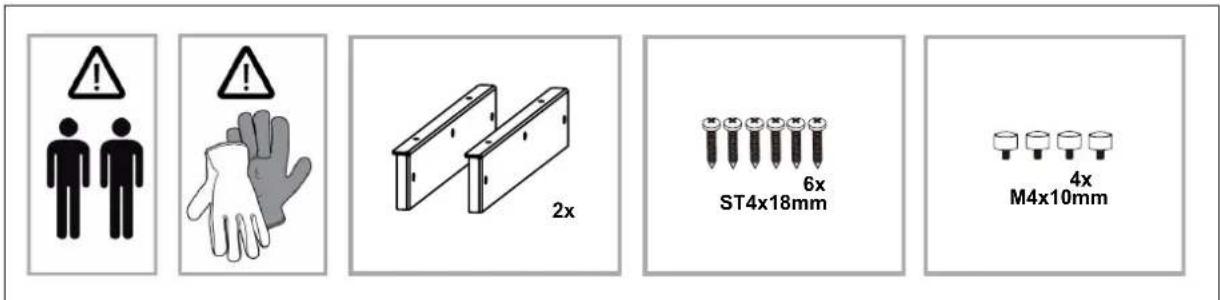
Technical line drawing of two rectangular metal components with bolt holes, labeled '2x' (no text or symbols on the components themselves)
natural_image
Floor plan diagram showing room layout with furniture placement and directional arrows (no text or labels)natural_image
Line drawing of a 3D rectangular enclosure with internal compartments and a small cylindrical component inside (no text or symbols)natural_image
Technical line drawing of a mechanical assembly with internal components and directional arrows (no text or symbols)natural_image
Isometric line drawing of a rectangular frame with internal compartments and a small protrusion (no text or symbols)i
معلومة
8
natural_image
Isometric line drawing of a rectangular frame with internal cutouts and a small protrusion (no text or symbols)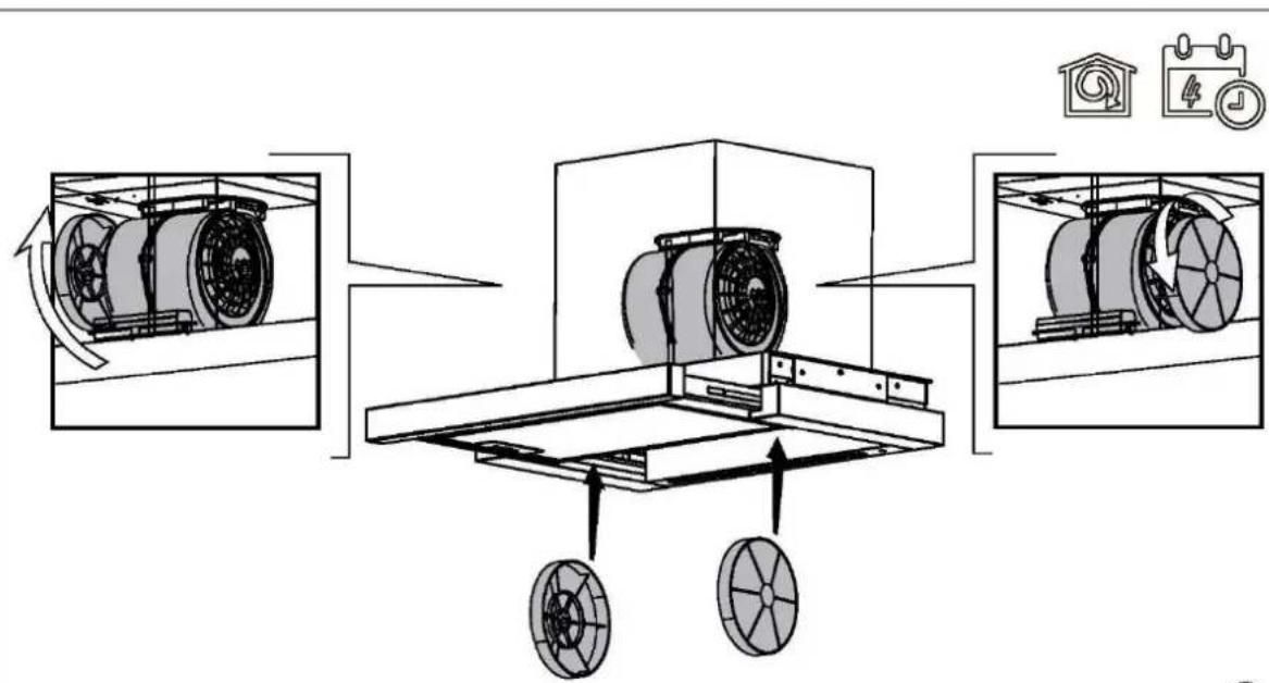
natural_image
Isometric line drawing of a rectangular frame with internal compartments and a vertical support (no text or symbols)

natural_image
Diagram of a mechanical setup with a cylindrical component being inserted into a base, connected to a cable via a plug (no text or symbols present)i
معوّة
natural_image
Close-up of a hand holding a small object on a textured surface, no visible text or symbols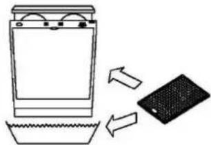
natural_image
Simple line drawing of a washing machine with a plate and water nearby, showing airflow direction (no text or symbols)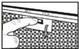
natural_image
Hand pressing a button on a textured surface with a curved arrow (no text or symbols visible)natural_image
Technical line drawing of a mechanical assembly with no visible text or symbolsnatural_image
Technical line drawing of a mechanical or electrical enclosure with internal components and directional arrows (no text or symbols)natural_image
Line drawing of a multi-level office or storage unit with internal compartments and a central door (no text or symbols)8
natural_image
Diagram of a mechanical setup with a cylindrical component being inserted into a base, connected to an electric plug (no text or symbols present)10
Controles
T1 = Tecla ENCENDIDO / APAGADO
flowchart
graph LR
    A["Grinding a washing machine"] --> B["Grinding a surface treatment"]
    B --> C["Grinding a water bath"]

Brand : HAIER
Model : HABT9CBS6XBSLC
Category : Basket