USB 7014 - DJ Equipment US Blaster - Free user manual and instructions
Find the device manual for free USB 7014 US Blaster in PDF.
| Product type | DJ Mixing Console |
| Brand | US Blaster |
| Model | USB 7014 |
| Microphone inputs | 2 XLR inputs with +48V phantom power |
| Line inputs | 6.3 mm balanced jack (mono) and stereo |
| Equalization | 3-band (Hi, Mid, Low) per channel, with mid frequency adjustment |
| Built-in effects | 16 digital effect modes (echo, etc.) |
| Main outputs | Main L/R unbalanced, headphones, monitoring |
| Insert input/output | 6.3 mm jack for external processor |
| Phantom power | +48V switchable per microphone channel |
| Frequency response | 20 Hz - 20 kHz (±1 dB) |
| Total harmonic distortion (THD) | <0.008% at 1 kHz |
| Microphone input noise | -128 dBu (max gain) |
| Crosstalk | < -90 dB (20 Hz - 10 kHz) |
| Microphone input impedance | 2 kΩ |
| Line input impedance | >40 kΩ (mono), >30 kΩ (stereo) |
| Max microphone input level | +12 dBu |
| Max line output level | +21 dBu |
| Care and cleaning | Slightly damp anti-dust cloth. Do not use cleaning products. |
| Safety | Do not use outdoors or in humid environments. Disconnect during thunderstorms. Keep out of reach of children. |
| Repairability | Repair by a US Blaster authorized professional. The user must not open or modify the device. |
Frequently Asked Questions - USB 7014 US Blaster
User questions about USB 7014 US Blaster
0 question about this device. Answer the ones you know or ask your own.
Ask a new question about this device
Download the instructions for your DJ Equipment in PDF format for free! Find your manual USB 7014 - US Blaster and take your electronic device back in hand. On this page are published all the documents necessary for the use of your device. USB 7014 by US Blaster.
USER MANUAL USB 7014 US Blaster
GENERAL SAFETY INSTRUCTIONS
- Always read the user guide before using the equipment.
- Keep the user guide in a place where everyone can read it.
- Use the equipment indoors and not in humid environments.
- Never remove or insert a plug from or into a wall socket with wet hands.
- If the plug and/or cable and/or cable input of the equipment is damaged it must be repaired by a professional.
- Always take the plug out of the wall socket in the event of a thunderstorm, and also when the equipment is not being used for a while.
- Never remove the plug from the power socket by pulling on its cable.
- Install the equipment in such a way that sufficient cooling is possible.
- Never use the appliance in the vicinity of heat sources and/or in direct sunlight.
- Make sure that no small objects or liquids can get in to the appliance.
- Only clean the appliance with a slightly moist dust-free cloth. Do not use cleaning products or solutions!
- The appliance contains no components, other than those mentioned in the user guide that can be repaired or replaced by the user.
- If the appliance is defective, it must be repaired by a US Blaster qualified repairs company.
- Keep the equipment out of the reach of children.
Do not carry out any repairs on the equipment yourself; doing so will invalidate the guarantee. The equipment may also not be modified; doing so will also invalidate the guarantee. The guarantee is also invalidated if accidents and damage of any form are caused as a result of improper use and/or not heeding the warnings in general as laid out in this user guide. US Blaster Europe accepts no responsibility for any personal accidents as a consequence of not following the safety instructions and warnings. This is also the case for consequential loss in any form.
Keep the packaging safe so that, if the equipment is defective, you can send it back in its original packaging and so avoid any damage.
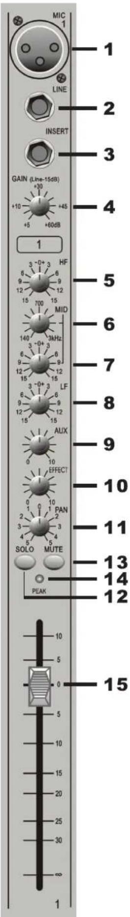
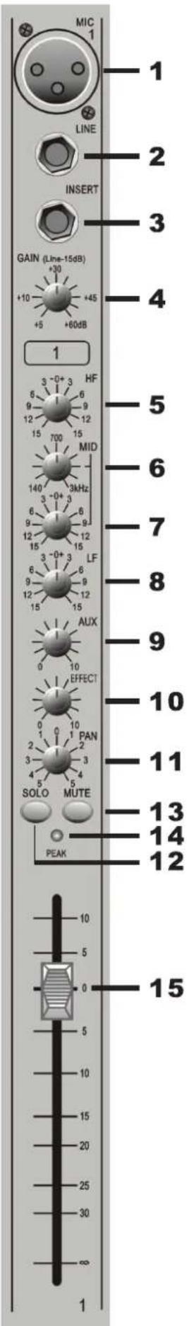
MONO INPUT CHANNELS
1. MIC INPUT
The MIC input accepts XLR-type connectors and is designed to use a wide range of BALANCED or UNBALANCED signals; it has 48V Phantom power supply and it can connect high capacity microphones.
Pin 1=Ground, Pin 2=signal+, Pin 3=signal-
2. LINE INPUT
Accepts 3-pole 6.3mm Jack. It uses this high impedance input for sources other than mics, such as keyboards, drum machines, synths, tape recorders or guitars. The input is BALANCED for professional equipment, but you can use UNBALANCED sources by wiring up the jacks as shown in the diagram. You should keep cable lengths as short as possible. Unplug anything in the MIC input if you want to use this socket. Set the input level using the SENS knob.
3.INSERT
The unbalanced, pre-EQ insert point is a break in the channel-signal path, allowing limiters, compressors, special EQ or other signal processing units to be added in the signal path. The insert is a 6.3mm Jack socket which is normally bypassed. When a jack is inserted, the signal path is broken, just before the EQ section. The send may be tapped off as an alternative prefade, pre-EQ direct output if required, using a lead with tip and ring shorted together so that the signal path is not interrupted.
4. GAIN
This knob sets how much of the source signal is sent to the rest of the mixer. Too high, and the signal will distort as it overloads the channel. Too low, and the level of any background hiss will be more noticeable and you may not be able to get enough signal level to the output of the mixer. Setting the knob to the "U" mark gives unity gain for the LINE input. Note that some sound equipment, particularly the ones for domestic use, operate at a lower level(-10 dB) than professional equipment and will therefore need a higher gain setting to give the same output level. See 'Setting UP & Troubleshooting' to learn how to set SENS correctly.
5. HI
Controls frequencies higher than 12kHz . Provides ± 15dB upgrade or attenuation.
6. FREQ
Control of frequency, can be adjusted from 140Hz to 3kHz
7. MID
Provides ± 15 dB upgrade or attenuation in the mid frequencies.
8. LOW
Controls frequencies below 80Hz , which features ± 15dB of gain adjustment (cut or boost).
USB 7013 - 7014
Console mixers
MONO INPUT CHANNELS
9. AUX
Used for monitoring the stage or playback room's return.
10. EFFECT
Lets the signal sent to inside or outside effectors.
11.FX
Can let the signal sent to inside or outside effectors. Can also be used for monitoring the stage or the return of recording.
12. SOLO
The FADER allows balancing of the various source signals being mixed to the Master section. You get most control when the input sensitivity is set up correctly; giving full travel on the fader, see the 'Setting Up & Troubleshooting' for help in setting a suitable signal level.
13. MUTE
All outputs from the channel except inserts are active when the MUTE switch is released and muted when the switch is down, allowing levels to be pre-set before the signal is required.
14. PEAK
This is the LED which indicates the input signal level of this appliance (regardless of output) when GAIN volume is adjusted.
15.FADER
The FADER allows balancing of the various source signals being mixed to the Master section. You get most control when the input Sensitivity is set up correctly, giving full travel on the fader. See the 'Setting up & Troubleshooting' section for help in setting a suitable signal level.

STEREO INPUT CHANNELS
1.MONITOR OUT
This jack is to be connected with the input jack of a monitor amplifier when using separate monitor amplifiers.
2/3.AUX1
Each of these six AUX outputs have a master output level control.
4.L/R PIN JACK
Used for connection of line level equipment. (Tape recorders etc.)
5.GAIN
The GAIN control sets the input level to the channel, allowing to match to a wide range of line level sources.
6.HF EQ
Turn clockwise to boost high (treble) frequencies, adding crispness to percussion from drum machines, synths and electronic instruments. Turn anticlockwise to cut these frequencies, reducing hiss or excessive brilliance. Set the knob in the center position when not required. The control has a shelving response giving 15 dB of boost or cut at 12kHz and above.
LF EQ
Turn clockwise to boost low (bass) frequencies, adding extra punch to synths, guitars and drums. Turn anticlockwise to reduce hum, boominess or improve a mushy sound. Set the knob to the centre position when not required. The control has a shelving response giving 15 dB of boost or cut at 60Hz and below.
7.AUX
This socket sends out the signals from aux bus.
8.EFFECT
Adjust this knob can send a signal to inside or outside effectors.
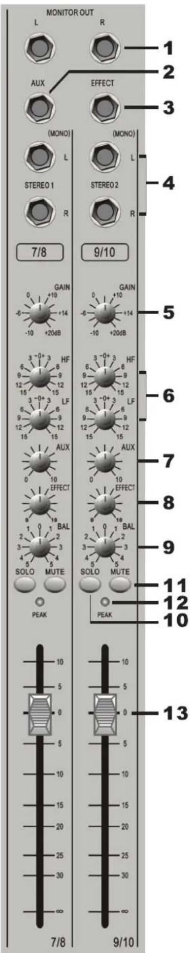
STEREO INPUT CHANNELS
9.BAL
This control sets the amount of the channel signal feeding the Left and Right MIX buses, allowing you to move the source smoothly across the stereo image. When the control is turned fully right or left you are able to route the signal at unity gain to either left or right outputs individually.
10. SOLO
When you want monitor echo sound and external effectors sound, you can adjust this control through the headphone.
11.MUTE
All outputs from the channel except inserts are active when the MUTE switch is released and muted when the switch is down, allowing levels to be pre-set before the signal is required.
12. PEAK
This is the lamp which indicates the input signal level of this appliance (regardless of output) when GAIN volume is adjusted.
13. FADER
The FADER allows balancing of the various source signals being mixed to the Master section. You get most control when the input Sensitivity is set up correctly, giving full travel on the fader. See the 'Setting up & Trouble shooting' section for help in setting a suitable signal level.
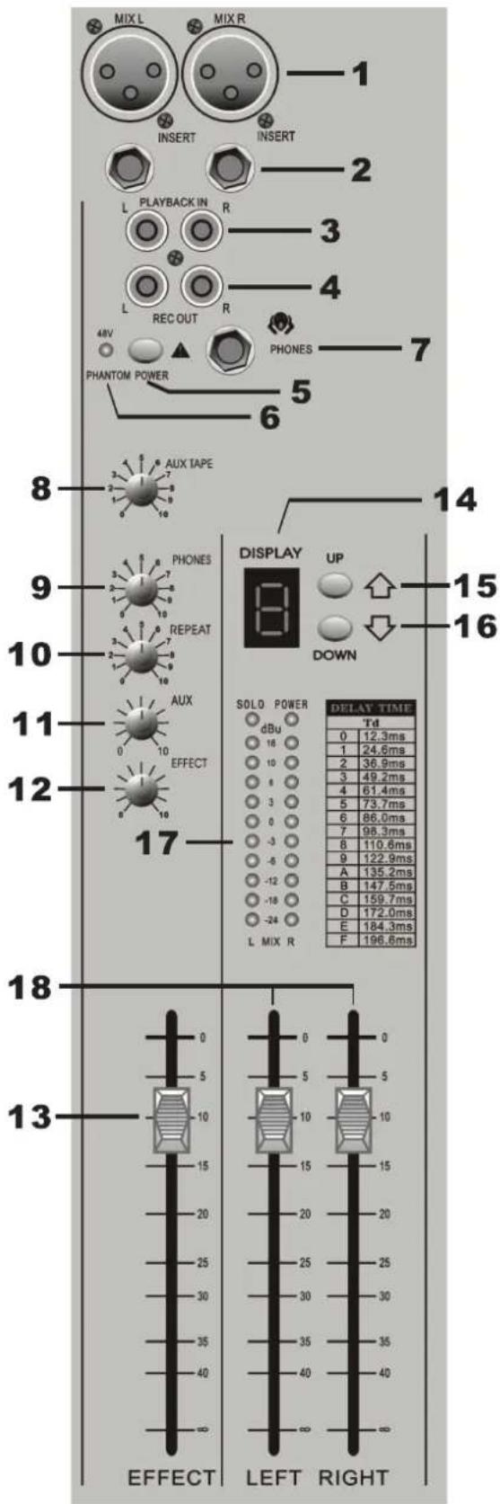
OUTPUT CHANNELS
1. BALANCE OUTPUT (MAIN L/R)
These sockets send line level signals from the mixer to external devices (for example: EQ or a power amplifier).
2. MIX INSERT (6.3 mm Jack)
This is a pre-fade break in the signal path which can be used to feed a dynamics or mastering device. The signal is sent from the tip of the jack plug and the return path comes back in on the ring of the jack plug.
3. PLAYBACK INPUTS (RCA RHONO)
Here you can connect the play back from your recording device
4. RECORD OUTPUTS
Here you can connect the input to your recording device.
5. PHANTOM +48V
This slide-switch turns the master phantom power on and off.
6. PHANTOM +48V LED
The LED will be lit when you press this phantom +48V lamp.
7. PHONES
Plug your headphones into this socket
8.AUXTAPE
This controls the level of the signal sent to your tape.
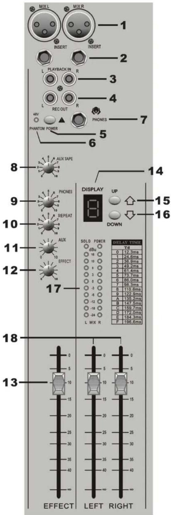
OUTPUT CHANNELS
9.PONES This controls the level of the signal sent to your headphones
10.REPAT This is used for adjusting frequency of echo repeat. Since too much echo repeat may cause a howl. Please adjust frequency properly.
11.MONITOR CONTROL This controls the level of the signal sent to your monitoring system.
12.EFFECT This is used for adjusting the volume of echo sound when connecting sound to RETURN jack.
13. EFFECT FADER
This is used for adjusting the volume of echo sound when connecting sound to RETURN jack.
14. DISPLAY The mixer display has 16 effect modes.
15. UP This control can choose the result mode if necessary.
16. DOWN This controls can choose the result mode if necessary.
17. BARGRAP H METERS 3-colorur peak reading BARGRAPH METERS are provided to monitor the four Subgroup outputs and the selected. Monitor + Phones source (2TK, Mono Mix or Groups), giving you a constant warning of excessive peaks in the signal which might cause overloading.Aim to keep the signal within the amber segments at peak levels for best performance. Similarly, if the output level is too ow and hardly registering at all on the meters, the level of background noise may become significant. Carefully set up the input level for best performance. When any PFL of AFL switch is pressed, the L&R meters auto matically switch to show the selected PFL/AFL signal both meters, in mono.
18. MASTER FADERS These faders control the overall level of the mix bus
SPECIFICATIONS
Frequency response
Mic/Line Input to any Output . + / - 1 dB 20Hz-20KHz
T.H.D
Mic Sensitivity +30dBu, +20dBu @ all Outputs <0.008%@1KHz
Noise
Mic input E.I.N (maximum gain, measured 22Hz, unweighted) .-128 dBu
Aux and Mix Outputs (8ch.routed. faders down, 22Hz,unweighted) . . . . . . . . . . . . . . . . . . . . . . . . . . . . . . . . . . . . . . . . . . . . . . . . . . . . . . . . . . . . . . . . . . . . . . . . . . . . . . . . .
Crosstalk
Channel Mute .<90dB 20Hz-10kHz, <80dB 10kHz-20kHz
Fader Cut-Off (ref. Fader OdB) <90dB 20Hz-10kHz, <80dB 10kHz-20kHz
Routing Isolation <90dB 20Hz-10kHz, <80dB 10kHz-20kHz
Input & output impedances
Microphone Input 2K Ohms
Mono Channel Line Input. .>40 K Ohms
Stereo Input (Stereo Mode) .>30 K Ohms
Stereo Returns . . . . . . . . . . . . . . . . . . . . . . . . . . . . . . . . . . . . . . . . . . . . . . . . . . . . . . ..>10 K Ohms
Headphones Output 40 Ohms
All Other Audio Outputs . 75 Ohms
Input & output levels
Microphone Input Maximum Level .+12 dBu
Mono Channel Line Input Maximum Level +38 dBu
Stereo Input Maximum Level 21 dBu
Headphones Output (into 200 Ohms) .150mV
All Other Audio Outputs . 21 dBu into 10 K Ohms
Filter
MF .240Hz-6 kHz, +/-15dB
Lf .60 Hz, +/-15dB

DIAGRAM
ALGEMENE VEILIGHEIDSVOORSCHRIFTEN
Pin 1 = aarde, Pin 2 = signal +, Pin 3 = signal -
2. LJNINGANG (LINE)
HF EQ (Bediening van lage frequencies)
3.INGANG VOOR WEERGAVE (RCA Cinch connector)
HF .12 kHz, +/-15 dB
MF .240 Hz-6 kHz, +/-15 dB
Lf .60 Hz, +/-15 dB

DIAGRAM
CONSIGNES GENÉRALES DE SECURITÉ
MF .240Hz-6 kHz, +/-15dB
Lf .60 Hz+/-15dB

DIAGRAM
MF .240Hz-6 kHz, +/-15dB
Lf .60 Hz, +/-15dB

DIAGRAM
- USCITA SIMMETRICA (MAIN L/R)
HF. 12 kHz, +/- 15 dB
MF .240 Hz-6 kHzm +/-15 dB
Lf .60 Hz, +/-15 dB

DIAGRAM
MF .240Hz-6 kHz, +/-15dB
Lf .60 Hz, +/-15dB
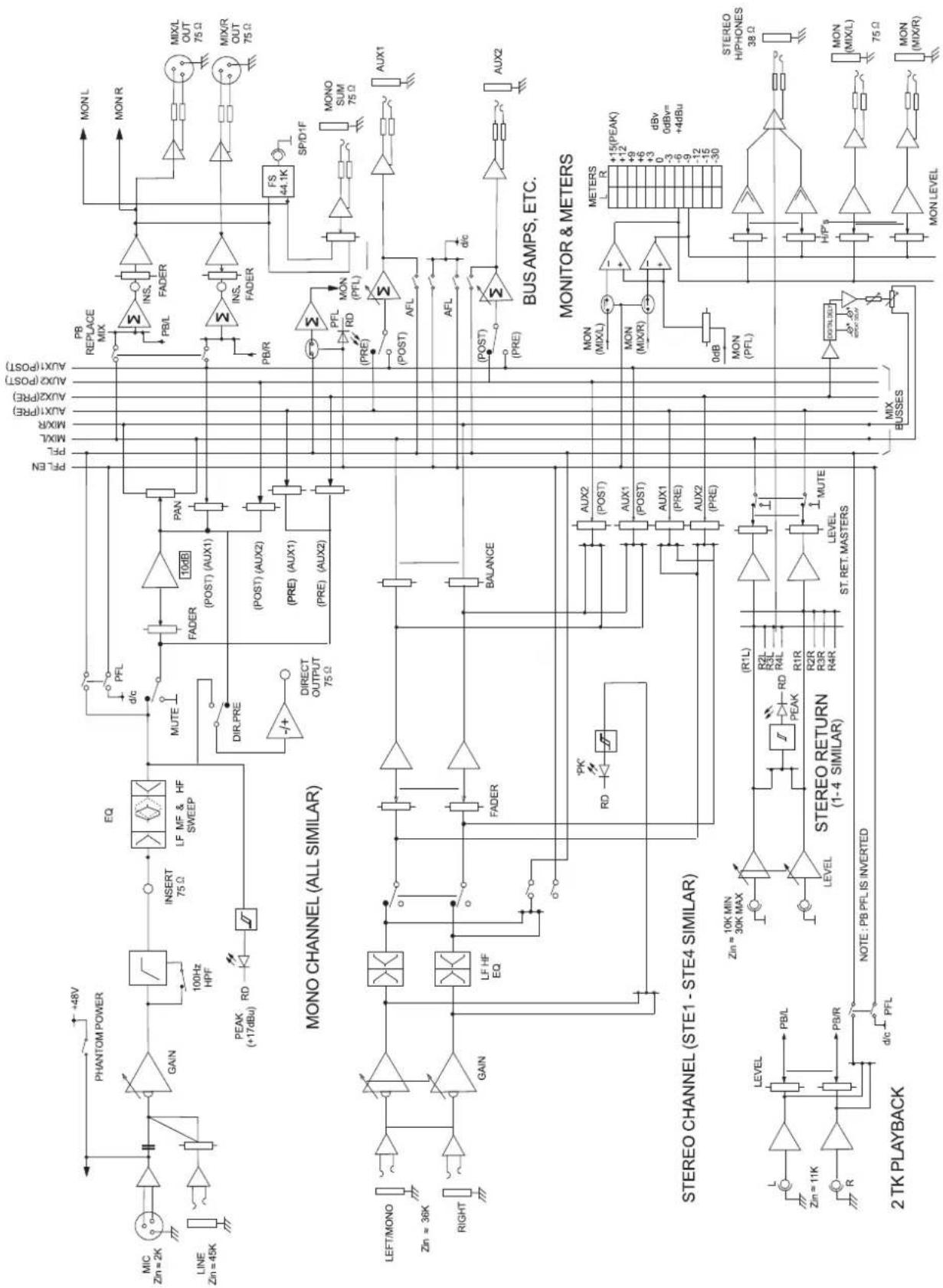
DIAGRAM