F 272 - Heating Jøtul - Free user manual and instructions
Find the device manual for free F 272 Jøtul in PDF.
| Product type | Wood stove |
| Brand | Jøtul |
| Model | F 272 |
| Main material | Cast iron |
| Fuel | Wood (logs only) |
| Maximum log length | 30 cm |
| Nominal heat output | 6.5 kW |
| Efficiency | 77% at 6.7 kW |
| CO rate at 13% O2 | 0.10% |
| Flue gas temperature | 327 °C |
| Recommended draft | 12 Pa |
| Flue gas mass flow | 5.5 g/s |
| Operating mode | Intermittent |
| Flue pipe diameter | 150 mm (section 177 cm²) |
| Connection flue | Top or rear |
| Weight (firebox only) | Approx. 120 kg |
| Weight (with options) | Up to 160 kg |
| Finish | Black or grey paint |
| Standard | EN 13240 |
| Routine maintenance | Empty ash pan, check seals |
| Spare parts available | Deflectors, lining plates, glass door, etc. |
| Options | Rotation kit, soapstone/glass decorations |
Frequently Asked Questions - F 272 Jøtul
User questions about F 272 Jøtul
0 question about this device. Answer the ones you know or ask your own.
Ask a new question about this device
Download the instructions for your Heating in PDF format for free! Find your manual F 272 - Jøtul and take your electronic device back in hand. On this page are published all the documents necessary for the use of your device. F 272 by Jøtul.
USER MANUAL F 272 Jøtul
GB - Installation Instructions with technical data 18
natural_image
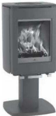
Exterior view of a modern office building (no signage)Jøtul F 271
natural_image
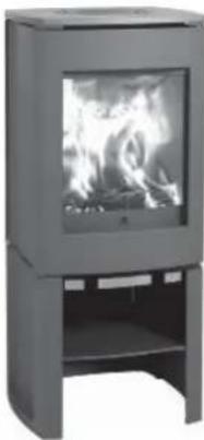
Exterior view of a modern office building (no signage)Jøtul F 272
natural_image
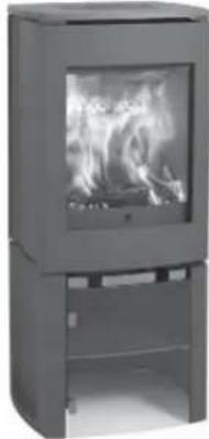
Exterior view of a modern portable stove with visible flames and a base (no text or symbols)Jøtul F 273
natural_image
Exterior view of a modern office building (no signage)Jøtul F 274
natural_image
Exterior view of a modern office building (no signage)Jøtul F 275
text_image
Jautel produkter/ Jautel's products 100% Concatikäk - opentilistätigkeit 2 3 4 5 6 7 8 9 10 11 12 13 14 15 16 17 18 19 20 21 22 23 24 25 26 27 28 29 30 31 32 33 34 35 36 37 38 39 40 41 42 43 44 45 46 47 48 49 50 51 52 53 54 55 56 57 58 59 60 61 62 63 64 65 66 67 68 69 70 71 72 73 74 75 76 77 78 79 80 81 82 83 84 85 86 87 88 89 90 91 92 93 94 95 96 97 98 99 100GB - Before use, please read the general users and maintenance manual carefully.
| Product Eventual | |||
| Item: Particular (Refrasyschafter) | |||
| Material | |||
| Material name and type of material used in the material. | |||
| Material type and type of material used in the material. | |||
| Material properties | |||
| Material knowledge | |||
| Ordering | |||
| Type of ordering | |||
| Type knowledge | |||
| the equipment is used in a software. | |||
| Country | Classification | Not-for-service | Approve by |
| Norway | Eventual | ||
| Website | dev | p | 2" Stages from one's to two's, but not more than 40 |
| E.R. | Institute | p | 2" Stages from one's to two's, but not more than 40 |
Installation manual with technical data
1.0 Relationship to the authorities .....18
2.0 Technical data ....18
3.0 Installation 19
4.0 Service 22
5.0 Optional Equipment 22
Figures 43
General use and maintenance manual
6.0 Safety precautions
7.0 Choice of fuel
8.0 Use
9.0 Maintenance
10.0 Operational problems - troubleshooting
text_image
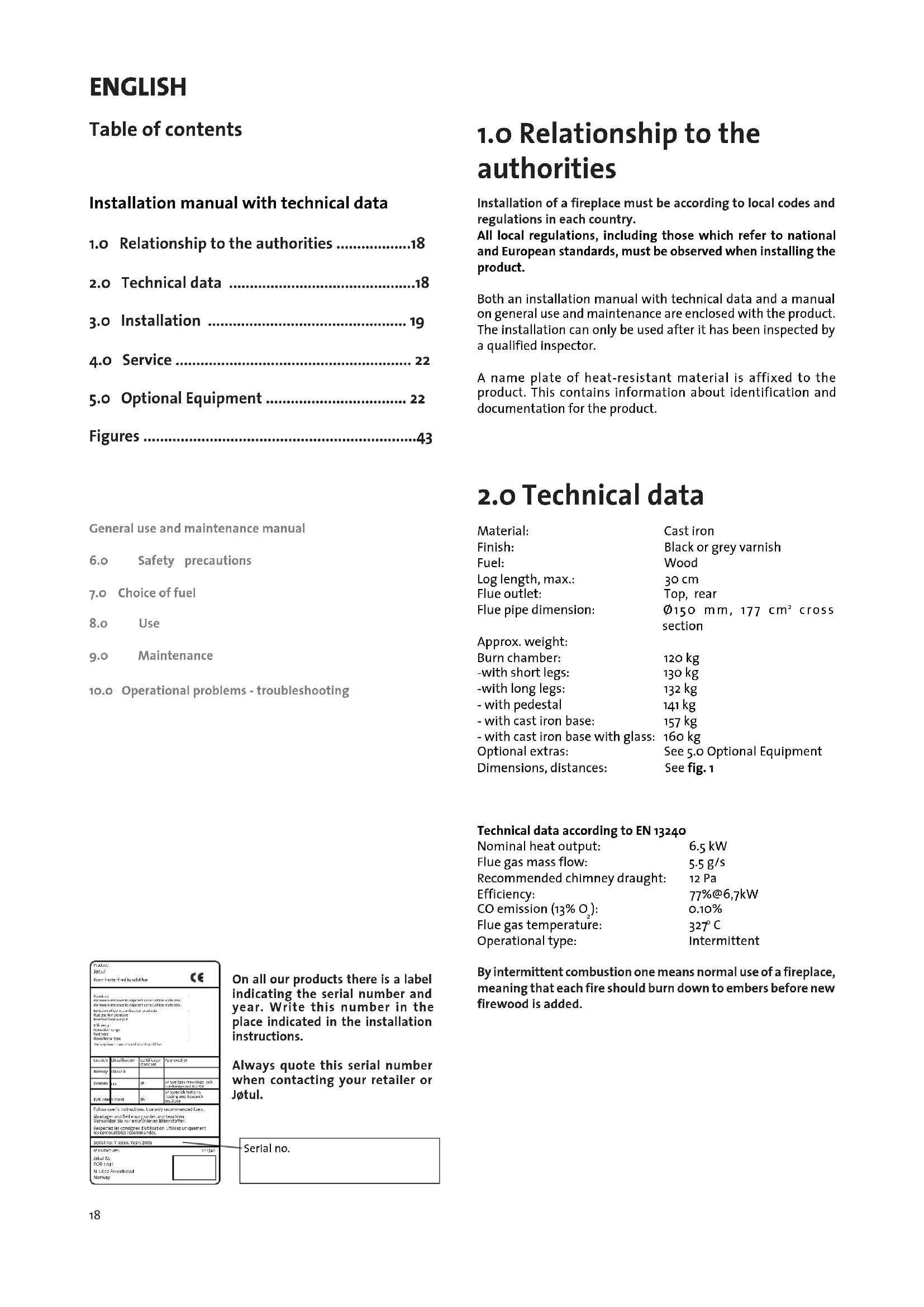
Product Detail Exhibit: Historic Realty and Sale CE Material: With material used to recommend existing materials. With material used to recommend existing materials. In order of material used in accordance with the requirements. Material not applied: Storage Storage unit: Line type: Line thickness: The equipment is designed as a material. Country Classification: No. 1-First Material Molecule: Enerel Material type: Type Oil treatment: Type Follow-up's instructions: Unless only recommended files: Morphs and Bedienungsanleitung brücher. Received file is not required by the manufacturer. Recommended conditions for location: Stowe uncompliant. No. 10000000000000000000000000000000000000000000000000000000000000000000000000000000000000000000000000000 Sediment Version, Year 26/26 Manufactured: 322419 Jaguar 45 POB 1444 No. 14441 (Copyright) NorwayOn all our products there is a label indicating the serial number and year. Write this number in the place indicated in the installation instructions.
Always quote this serial number when contacting your retailer or Jøtul.
Serial no.
1.0 Relationship to the authorities
Installation of a fireplace must be according to local codes and regulations in each country.
All local regulations, including those which refer to national and European standards, must be observed when installing the product.
Both an installation manual with technical data and a manual on general use and maintenance are enclosed with the product. The installation can only be used after it has been inspected by a qualified inspector.
A name plate of heat-resistant material is affixed to the product. This contains information about identification and documentation for the product.
2.0 Technical data
| Material: | Cast iron |
| Finish: | Black or grey varnish |
| Fuel: | Wood |
| Log length, max.: | 30 cm |
| Flue outlet: | Top, rear |
| Flue pipe dimension: | 150 mm, 177 cm ^2 cross section |
Approx. weight:
| Burn chamber: | 120 kg |
| -with short legs: | 130 kg |
| -with long legs: | 132 kg |
| - with pedestal | 141 kg |
| - with cast iron base: | 157 kg |
| - with cast iron base with glass: | 160 kg |
| Optional extras: | See 5.0 Optional Equipment |
| Dimensions, distances: | See fig. 1 |
Technical data according to EN 13240
| Nominal heat output: | 6.5 kW |
| Flue gas mass flow: | 5.5 g/s |
| Recommended chimney draught: | 12 Pa |
| Efficiency: | 77%@6,7kW |
| CO emission (13% O_2 ): | 0.10% |
| Flue gas temperature: | 327°C |
| Operational type: | Intermittent |
By intermittent combustion one means normal use of a fireplace, meaning that each fire should burn down to embers before new firewood is added.
Wood consumption
Jøtul F270 has a nominal heat output of 6,5 kW. This is equivalent to a consumption of approximately 2,0 kg of quality firewood per hour.
Kindling:
Length: 20-30 cm
Diameter: 2-5 cm
Amount per fire: 6-8 pieces
Firewood (split logs):
Length: Ca 25 cm
Diameter: Approx. 8 cm
Intervals for adding wood: Approximately every 45 minutes
Size of the fire: 1.5 kg
Amount per load: 3 pieces
Nominal heat emission is achieved when the air wash vent is open approximately 50% (fig. 10A), and the handle for the lighting valve is pulled out approximately 1-2 cm (fig. 10B). In this position the ignition vent is now completely closed but the grate is open.
3.0 Installation
3.1 Floor
Foundations
It must be ensured that the foundations are dimensioned for the fireplace. Cf. «2.0 Technical data» for specification of weight. It is recommended that flooring which is not fastened to the foundations – so-called floating flooring – is removed during installation.
Combustible floor protection
If the fireplace is to be mounted on a combustible floor, cover the floor under and in front of the fireplace with a plate made of metal or other non-combustible material. The recommended minimum thickness is 0.9 mm.
Any flooring made of combustible material, such as linoleum, carpets, etc. must be removed from under the floor plate.
Requirement for protecting combustible flooring in front of fireplace
The front plate must be in accordance with national laws and regulations.
Contact your local building authority regarding restrictions and installation requirements.
3.2 Walls
Distance to wall made of combustible material - see fig. 1.
You may use the fireplace with an uninsulated flue pipe provided the distances to walls made of combustible materials are as shown in fig. 1.
Distance to walls covered by a firewall
Contact your local building authority regarding restrictions and installation requirements.
Firewall requirement
The firewall must be at least 100 mm thick and be made of brick, concrete-stone or light concrete. Other materials and constructions with satisfactory documentation may also be used.
3.3 Ceiling
There must be a minimum distance of 1000 mm to a combustible ceiling above the fireplace.
ENGLISH
3.4 Chimneys and flue pipes
- The fireplace can be connected to a chimney and flue pipe approved for solid fuel fired appliances with flue gas temperatures specified in «2.0 Technical data.
- The chimney's cross-section must be at least as big as the flue pipe's cross-section. See «2.0 Technical data» when calculating the correct chimney cross-section.
- Several solid fuel fired appliances can be connected to the same chimney if the chimney's cross-section is sufficient.
- Connection to the chimney must be carried out in accordance with the installation instructions from the supplier of the chimney.
- Before making a hole in the chimney the fireplace should be test-mounted in order to correctly mark the position of the fireplace and the hole in the chimney. See fig. 1 for minimum dimensions.
- Ensure that the flue pipe is inclined all the way up to the chimney.
- Use a flue pipe bend with a sweeping hatch that allows it to be swept.
Be aware of the fact that it is particularly important that connections have a certain flexibility in order to prevent movement in the installation leading to cracks. N.B. A correct and sealed connection is very important for the proper functioning of the product.
Chimney draught; See «2.0 Technical data». If the draught is too strong you can install and operate a flue damper to control the draught.
3.5 Assembly prior to installation
N.B. Check that the fireplace is free of any damage prior to commencing installation.
The product is heavy! Make sure you have assistance when erecting and installing the fireplace.
- The standard product is delivered in two packing cases. One containing the fireplace itself and one containing optional legs, short/long or pedestal.
- Once you have unpacked the product, remove the fire grate and the heat shield.
- Lift off the top plate and the air grid and bowl.
- Lift off the rear heat shield (cast iron). This hangs on 3 screws, two above and one below. See fig. 9A.
- Check that the product does not have any visible damage and that the operating handles work.
- Unfold the cardboard packing and place the wooden pallet on top. Carefully place the fireplace on its back.
Jøtul F 271/F 272 - Attaching the legs
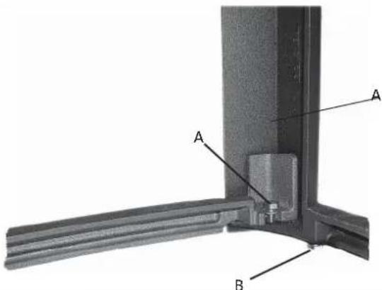
- Unscrew the screws that are screwed in the corners of the fireplace, and attach the legs to the screws (fig. 2A).
- Attach the stiffener between the rear legs - see fig. 3A.
- The floor shall be protected from heat from the product using the supplied heat shield. Attach it to the 4 screws as shown in fig. 4.
- Make sure to have assistance and lift the product carefully up.
- Adjust the product with the aid of the 4 adjusting screws in each corner (see fig. 3B).
- Re-attach the rear heat shield (cast iron) by first hanging it on the top screws. Lift it up slightly and then lower it onto the lower screw.
- Replace the top plate with the air grid and bowl.
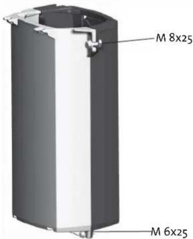
Jøtul F 273 - Attaching the column
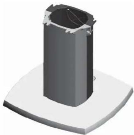
- The pedestal consists of 4 parts, the pedestal foot, 2 pedestal parts and an air chamber.
- Screw the pedestal sections together using 2 bolts M8 x 25 and 2 bolts M6 x 25, as shown in fig. 5A.
- Screw the pedestal to the foot plate using 4 bolts (M8 x 25), see fig. 5B-6B.
Turn plate
If the turn plate shall be mounted, this shall be done now before the base plate is attached to the fireplace. See the installation instructions that are included with the turn plate.
-
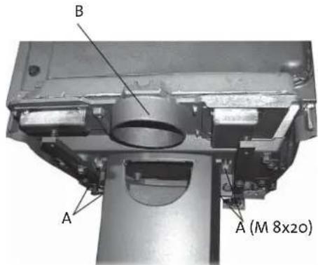
Attach the pedestal to the fireplace's base plate using 4 bolts (M8 x 20), see fig. 5C. The seams on the pedestal shall face the sides of the product and the opening for outdoor air shall face backwards (see: «Fresh air supply through the base»).
-
Make sure to have assistance and lift the product carefully up.
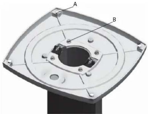
6 Adjust the product with the aid of the 4 adjusting screws in each corner (see fig. 6A).
-
Re-attach the rear heat shield (cast iron) by first hanging it on the top screws. Lift it up slightly and then lower it onto the lower screw.
-
Place the top plate in position with the air grid and bowl.
- Unscrew the screws that are screwed in the corners of the fireplace, and attach the legs to the screws (fig. 2A).
- The floor shall be protected from heat from the product using the supplied heat shield. Attach it to the 4 screws as shown in fig. 4.
- Make sure to have assistance and lift the product carefully up.
- Adjust the product with the aid of the 4 adjusting screws in each corner (see fig. 3B).
- Re-attach the rear heat shield (cast iron) by first hanging it on the top screws. Lift it up slightly and then lower it onto the lower screw.
- Replace the top plate with the air grid and bowl.
If external air supply through the external air vent is to be used, connect a flexible hose, ∅ 100 mm, to the external air vent (Fig. 4C) on the product at this stage.
Installation with external air supply
- Push the lever on the external air vent to its forward position (Fig. 10 A).
- Attach the hose to the external air vent using a hose clip. NB! Make sure the hose is long enough so that joints are not necessary.
- Push the cast iron base toward the burn chamber and, at the same time, push the external air hose through the foot and, if necessary, through the opening in the back edge of the cast iron base.
- Attach the base to the burn chamber using the 4 screws (M8 x 30 mm) from the bag of screws.
- With the help of another person, carefully raise the product and position it correctly over the external air supply.
- Adjust the height of the product, if necessary, using the adjustment screws beneath the foot (Fig. 3B).
Installation without external air supply
- Attach the base to the burn chamber using the 4 screws (M8 x 30 mm) from the bag of screws.
- With the help of another person, carefully raise the product.
- Adjust the height of the product, if necessary, using the adjustment screws beneath the foot (Fig. 3B).
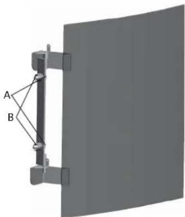
Jøtul F 275 – Cast iron base with glass door (Fig. 15 and 16)
- The floor shall be protected from heat from the product using the supplied heat shield. Attach it to the 4 screws as shown in fig. 4.
- Assemble the cast iron base as described under "Jøtul F 274 – Cast iron base."
- Attach the hinge for the glass door to the base using the M6x20 mm screws, which are in the bag of screws for the glass door (Fig. 15 A).
- Insert the spring between the threaded holes and the hinge before tightening the screws (Fig. 15 B).
- Screw the other end of the spring firmly in position (Fig. 16 A).
- Attach the door damper on the inside of the glass door in the middle (Fig. 16 D). NB! There must be an even gap between the door and the base to allow the door to hang straight. Adjust the door, if necessary, by tightening or loosening the two screws (Fig. 16 C).
Supply of outdoor air
With the F 270 it is possible to have outdoor air directly in the product through the base, or through the flexible supply tube from the exterior/chimney and to the connecting pipe on the product.
Fresh air supply through the base
- Mark where the product will stand, and make a hole in the floor for insertion of tube from outdoor air.
- Punch out the opening in the back of the pedestal from the inside (fig. 5A), and mount the air channel as fig.7A shows.
Fresh air supply direct from the exterior or from the chimney with air vents.
- Attach a flexible tube 100 mm directly to the fireplace's connecting pipe (fig. 5C-B) by using a hose clamp and attach it to the wall outlet/chimney. If the product shall be turned, this must be taken into consideration in terms of the length of the tube
- Make sure to have assistance and lift the product carefully up.
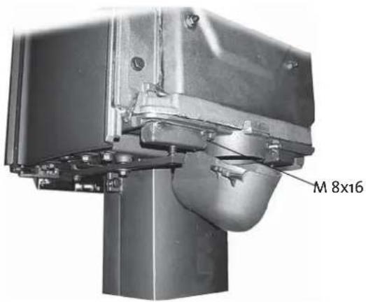
Mounting the flue pipe
The product is delivered from the factory with the smoke outlet mounted for top flue outlet. If one wants the pipe to come out of the rear the following should be done:
- Lift off the top plate
- Lift off the back heat shield (cast iron). This hangs on 3 screws, two above and one below. See fig. 9.
- Use a ball-pane hammer and knock out the cut-out in the heat shield from the inside.
- Swap the cover and the smoke outlet (fig. 8) and attach these.
- Re-attach the rear heat shield (cast iron) by first hanging it on the top screws. Lift it up slightly and then lower it onto the lower screw.
- Put the flue pipe into place inside the smoke outlet and seal tightly with a gasket.
Be aware of the fact that connections must have a certain flexibility in order to prevent movement in the installation leading to cracks.
N.B. A correct and sealed connection is very important for the proper functioning of the product.
The chimney draught, see «2.0 Technical data». If the draught is too strong you can install and operate a flue damper to control the draught.
3.6 Control of functions (fig. 10)
When the product is set up, always check the control functions. These shall move easily and function satisfactorily.
Jøtul F 270 is equipped with the following controls:
Air vent fig. 10A
Left position: Closed.
Right position: Open.
Ignition vent, fig. 10B)
Pushed in: Closed.
Pulled out: Open.
Oscillating grate fig. 10A
Right handle is pushed in and out
is opened by pulling handle out.
3.7 Ash removal
Jøtul F 270 has an ash pan which makes it easy to remove the ashes.
- Only remove ashes when the fireplace is cold.
- Push/pull the handle for the ash grate/ignition vent out and in several times so that the ashes fall down into the ash pan.
- Pull out the ash pan and empty the ash into a non combustible container.
- Ideally some ash should be left as a protective layer for the bottom of the fireplace.
For the rest, see description of how to handle ash in the Manual on general use and maintenance in Point «6.1 Fire preventive measures».
ENGLISH
4.0 Service
Warning! Any unauthorised change to the product is illegal. Only use original spare parts.
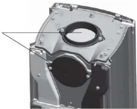
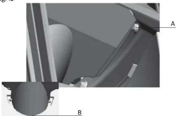
4.1 Replacing the baffle/exhaust deflector, fig. 11 and 12
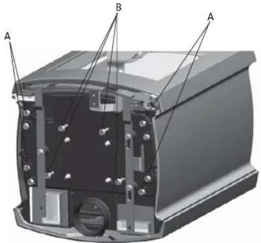
- The baffle plates rest on ribs in the side (11A) and on the burn plate on the back edge (11B). Lift the front edge of the baffle, push it to the right, lower the left edge and then tilt it out.
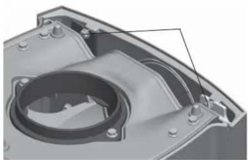
- The exhaust deflector, in cast iron - that is located above the baffle plate, rests on two screws in the front (12A) and in the groove by the rear flue outlet (12B). Lift the exhaust deflector slightly up, pull it forward and tilt it out.
- For reassembly follow the same procedure for installation, but in reverse.
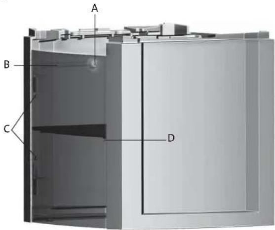
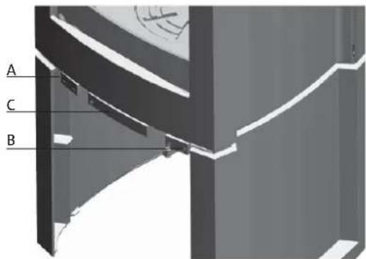
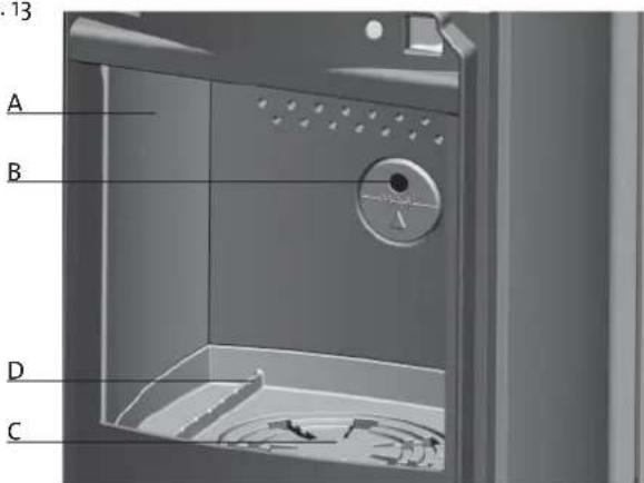
4.2 Changing the burn plates/base plate fig. 13
- Lift out the baffle plates as described above.
- Remove the side burn plates (A) by lifting them up slightly and forward - move them towards the middle and lift them out. (N.B. If you use tools be aware that the vermiculite plates may be damaged by rough treatment).
- Unscrew the screw back on the rear burn plate (B) and lift the burn plate out.
- Then lift up the grate(C) and the base plate (D) and take it out.
- Follow the same procedure for installation, but in the opposite sequence.
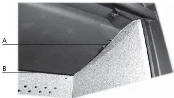
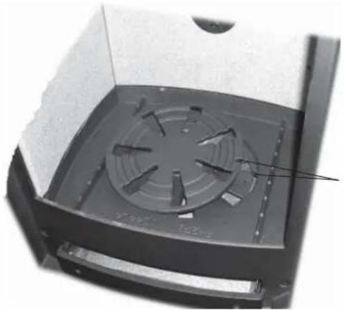
- When reassembling the grate and the base plate make sure that the tab that moves the fire grate is placed in the slot on the right edge of the base plate, and in the groove in the fire grate. (See fig. 14)
5.0 Optional equipment
5.1 Rotation set - cat. no. 350997
Assembly instructions are included with the product
5.2 Decoration
Soapstone decoration, top-cat. no. 350949
Glass decoration, top plate- cat. no. 350946
Glass decoration, sides-cat. no. 350947
Assembly instructions are included with the product
Glass decoration, door-cat. no. 350948
Assembly instructions are included with the product
Glass door kit, for Jøtul F 275 - cat. no. 361003
Soapstone complete, for Jøtul F 273 - cat. no. 361007
Soapstone complete, for Jøtul F 274 - cat. no. 361008
Soapstone top, 50 mm complete - cat. no. 361009
Heat shield for soapstone (Jøtul F 273 / Jøtul F 274) - cat. no. 224042
Sommaire
text_image
Product Detail Exhibit: Historic Realty and Sale CE Material: With material used to recommend existing materials. With material used to recommend existing materials. In order of material used in accordance with the requirements. Material not applied: Storage Storage unit: Line Line type: Special type: The equipment is designed as a material. Country Classification: No. 1-First Material Apply by: Material: Advanced Material: Type: Pb 2" Stages from first part of the material, including the material in line. B.R. requirement: Pb Follow us with instructions. Use only recommended files. Morphs and Bedienungsanleitung brücher. Received file is not recommended for any additional. Recommended requirements for the location. Since uncorrected. No. 10000000000000000000000000000000000000000000000000000000000000000000000000000000000000000000000000000 Sealment: Vancor, Vener, 2676 Manufactured: 232419 Jaguar 45 POB 1444 No. 1444/Industrial NorwayJøtul F 274 – Base in ghisa
text_image
Product Detail Exhibit: Historic Realty and Sale CE Material: With material used to recommend existing materials. With material used to recommend existing materials. In order of material used in accordance with the requirements. Material not applied: Storage Storage unit: Line type: Line thickness: The equipment is designed as a material. Country Classification: No. 1-First Material Mogeneity: Standard Sensitivity: Yes R & m (m) [0,1] [2] Stamps from first section of the material for the R & m (m) [48] R & m (m) [0,1] [2] Stamps from second section of the material for the R & m (m) [49] Follow-up's instructions: Unless only recommended files: Montage and Bedingenanleitung brother, Recommended by the reemploymenter of the following: Recommended for the use of the material: No. 1-50000000000000000000000000000000000000000000000000000000000000000000000000000000000000000000000000000 Sealment: Vancor, Vener, 2676 Manufactured: 322143 Jaguar 45 POB 1444 No. 1-5/2-1 Manufactured: NorwayStookopening, afb. 10B
Ingeduwd: gesloten
Uitgetrokken: open
Schudrooster afb. 10B
natural_image
3D rendering of a mechanical housing component with internal components and mounting holes (no text or symbols visible)Fig. 5 B
natural_image
3D rendered image of a cylindrical mechanical component mounted on a base plate (no text or symbols visible)Fig. 2
text_image
A B AFig. 3
text_image
A A BFig. 5 A
text_image
M 8x25 M 6x25Fig. 5 C
text_image
B A A (M 8x20)Fig. 6
natural_image
3D mechanical component diagram showing a flanged housing with labeled points A and B (no text or symbols beyond labels)Fig.7
text_image
M 8x16Fig. 8
natural_image
3D mechanical component diagram showing internal cavities and mounting holes (no text or symbols)Fig. 9
natural_image
3D mechanical component diagram showing internal cavity and mounting holes (no text or symbols)Fig. 10
text_image
A C BFig. 11
text_image
A BFig. 12
natural_image
Close-up of a mechanical component with labeled parts A and B, showing internal structure and mounting points (no text or symbols beyond labels)Fig. 13
text_image
A B D CFig. 14
natural_image
Interior view of a mechanical device with a circular fan or vent, showing internal blades and mounting holes (no text or symbols visible)Fig. 15
natural_image
Mechanical assembly diagram showing two labeled components A and B connected by rods, mounted on a curved panel (no text or symbols beyond labels)Fig. 16