I 18 - Heating Jøtul - Free user manual and instructions
Find the device manual for free I 18 Jøtul in PDF.
| Product type | Wood stove |
| Brand | Jøtul |
| Model | I 18 |
| Material | Cast iron |
| Surface treatment | Paint or enamel |
| Fuel | Wood exclusively |
| Max log length | 50 cm |
| Weight | 186 kg |
| Nominal power | 10.0 kW |
| Efficiency | 81 % (at 10.3 kW) |
| Recommended draft | 14 Pa |
| Flue gas temperature | 278 °C |
| CO rate (at 13 % O2) | 0.09 % |
| Flue gas mass flow | 8.9 g/s |
| Operating mode | Intermittent |
| Hot air outlet | 80 mm |
| Combustion air supply | Top / rear |
| Standard | EN 13229 |
| Optional accessories | Side panels, top band, convection chamber |
Frequently Asked Questions - I 18 Jøtul
User questions about I 18 Jøtul
0 question about this device. Answer the ones you know or ask your own.
Ask a new question about this device
Download the instructions for your Heating in PDF format for free! Find your manual I 18 - Jøtul and take your electronic device back in hand. On this page are published all the documents necessary for the use of your device. I 18 by Jøtul.
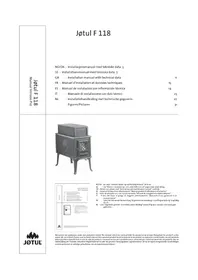
USER MANUAL I 18 Jøtul
GB-Installation and Operating Instructions 10
frontlist (topp), smale sideluster,
konveksjonskammer
Produktmål, murmal etc.: Se fig.1
Tekniske data i h.h.t. EN 13229
Nominell varmeavgivelse: 10,0 kW
Røykgass massestrøm: 8,9 g/s
4.6 Klargjøring/montering
1.0 Relationship to the authorities. 10
2.0 Technical data 10
3.o Safety precautions. 11
4.0 Installation 11
5.0 Operating Instructions 13
6.0 Maintenance 15
7.0 Service 16
8.o Operational problems - troubleshooting ....16
9.0 Optional equipment 16
Figures 48
1.0 Relationship to the authorities
Installation of a fireplace must be according to local codes and regulations in each country.
All local regulations, including thosethat refer to national and European standards, shall be complied with when installing the product.
Instructions for mounting, installation and use are enclosed with the product. Prior to using the product the installation must be inspected by a qualified person.
A product data label in heat resistant material is located on the heat shield at the back of the product. This contains information about identification and documentation for the product.
2.0 Technical data
Material: Cast iron
Finish: Paint/enamel
Fuel: Wood
Log length, max.: 50 cm
Flue outlet: Top/rear
Flue dimension:
inside: 175mm / 240cm cross section
outside: 200mm / 314cm
Inlet - combustion air: 80mm
Approx. weight: 186kg
Optional equipment: Ash solution with riddling grate, side- and front trim panels, convection chamber
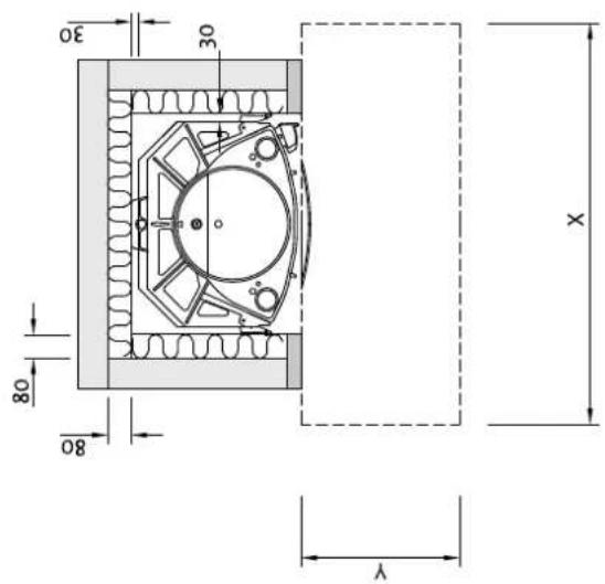
Dimensions, distances etc. See fig.1
Technical data according to EN 13229
Nominal heat output: 10,0 kW
Smoke gas mass flow: 8,9 g/s
Recommended chimney draught: 14 Pa
Efficiency: 81%@10,3 kW
CO emission (13% O2): 0,09%
Flue gas temperature: 278
Operating mode: Intermittent
3.0 Safety precautions
3.1 Fire preventive measures
Any use of the fireplace may represent some danger. Therefore, respect the following instructions:
- Ensure that furniture and other flammable materials do not get too close to the fireplace.
- Let the fire die. Never put it out with water as this may damage the product.
- The fireplace gets warm when used and may cause burns if touched.
- Only remove the ashes when the fireplace is cold.
- Ash must be properly disposed of outdoors, or emptied where it does not entail a fire hazard.
3.2 Air supply
Warning! Please ensure that there is adequate air supply from the outdoors to the room in which the fireplace is to be installed.
An inadequate air supply could cause smoke gas to escape into the room. This is very dangerous! Symptoms of this include smoky smell, drowsiness, nausea and feeling ill.
Ensure that air vents in the room where the fireplace is located are not blocked.
Avoid using mechanical fan vents in a room with a fireplace. This may cause negative pressure and draw poisonous gasses into the room
4.o Installation
4.1 Floor
Foundations
Ensure that the floor is strong enough for the fireplace. See «2.0 Technical data» for weights.
Wooden floor protection
If the fireplace is to be mounted on a combustible floor, cover the floor under and in front of the fireplace with a plate made of metal or other non-combustible material. The recommended minimum thickness is 0.9mm .
The floor plate must be in accordance with national laws and regulations.
Any flooring made of combustible material, such as linoleum, carpets, etc. must be removed from under the floor plate.
Requirement for protecting combustible flooring in front of fireplace
The front plate must be in accordance with national laws and regulations. Contact your local building authorities regarding restrictions and installation requirements.
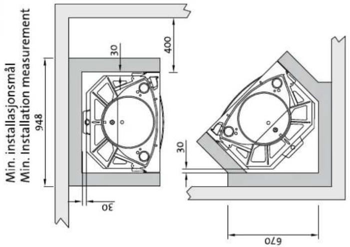
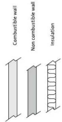
4.2 Wall
Distance to walls made of combustible material - see fig. 1
Requirements for insulation
80 mm rock wool 120kg / m^3 foliated on one side with aluminium.
Contact your local building authorities regarding restrictions and installation requirements.
Distance from the stove to the insulation on the back panel. See fig.1 and 2:
Minimum 30 mm.
Requirements for the stove surround
The insert surround must be made in an incombustible material.
Note that the entire back panel within the surround must be covered by insulation.
If the stove cowling is bricked up to the ceiling and the ceiling is made of combustible material, on top of the warming chamber and the cowling vents an extra ceiling panel must be installed to avoid heating the ceiling.
For example use:
Rock wool 100 mm thick on top of a steel plate min. 0,9 mm.
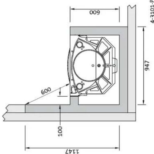
Ensure airing out the top of the stove cowling - for example an opening towards the ceiling, or approx. 5cm opening (fig. 2).
Note: Remember that it should be possible to sweep and to inspect the installation.
ENGLISH
4.3 Air supply (fig. 2)
Air should be allowed to flow between the insert and the brickwork, and it is very important that there is a free air supply to the draft catchers on top of and under the insert.
The required air vent sizes for J0tul 18 (for air circulation) are: Base: Minimum of 750~cm^2 free ventilation.
Top: Minimum of 1000 cm² free ventilation.
This is a safety measure to prevent a build up of heat in the surround, and also to ensure sufficient heat emission into the room.
If the house is badly ventilated, the room must be equipped with extra fresh air circulation, for example by means of separate air channels or a separate channel directly to the top of the fireplace.
The fresh air channel should be as straight as possible. Channels in the stove must be made of fire-proof materials.
4.4 Ceiling
Jotul 18 should have a min. 500mm distance from warm air opening in the hood's top to a ceiling of combustible material.
4.5 Chimney
- The fireplace can be connected to a chimney and flue pipe approved for solid fuel fired fireplaces with flue gas temperatures specified in «2.0 Technical data».
- The chimney's cross-section must be at least as big as the flue pipe's cross-section. See «2.0 Technical data» when calculating the correct chimney cross-section.
- The fireplace must be connected to a separate chimney. Contact your local building authorities regarding restrictions and installation requirements
- Connection to the chimney must be carried out in accordance with the installation instructions from the supplier of the chimney.
- Before making a hole in the chimney the fireplace should be test-mounted in order to correctly mark the position of the fireplace and the hole in the chimney. See fig. 1 for minimum dimensions.
- Ensure that the flue pipe is inclined all the way up to the chimney.
- Use a flue pipe bend with a sweeping hatch that allows it to be swept.
Be aware of the fact that connections must have a certain flexibility in order to prevent movement in the installation leading to cracks.
N.B! A correct and sealed connection is very important for the proper functioning of the product.
Warning! Weight from the fireplace must not be transferred to the chimney. The fireplace must not interfere with the ability of the chimney to move and it must not be fastened to the chimney.
Note: A guide is published by the British Flue and Chimney Manufacturers' Association which contains general information on chimneys and flues.
Recommended chimney draught: See section «2.o Technical data». If the draught is too strong you can install and operate a flue damper to control the draught.
In case of chimney fire
- Close all hatches and vents.
- Keep the firebox door closed.
- Check the loft and cellar for smoke.
- Call the fire service.
- Before use after a fire an expert must check the fireplace in order to ensure that it is fully functional.
4.6 Preparation/installation
Make sure that the fireplace insert is free of damage before commencing with the installation.
Attaching the legs (fig. 5)
- Unpack the insert.
- Take out all the loose parts, such as the baffle plate, burn plates and bottom plate.
- Place the wooden pallet and the cardboard packaging on the floor and lay the fireplace carefully down on its back.
- Fit the three legs (5D) using 3 hex. head screws M8x35 mm with nuts and washers.
- Fit the adjustable extension pieces to the legs so that the ash container (fig. 10A) is lifted at least 100mm above the floor. Fix the extension pieces to the legs with hex. head screws M6 x 25 mm, and nuts.
- For fine height adjustment, screw and M10 x 35 mm hex. screw into the end of each adjustable extension piece.
Assembly of the heat shield (fig. 5)
Unscrew the bolt (fig. 5B) in the centre of the bottom plate until the crossbar (fig. 5A) comes loose. Position the heat shield (fig. 5C) on the bolt (fig. 5B) from underneath with the countersunk facing downwards and the notch facing the leg. Secure the heat shield to the bolt with a M6 nut.
- Place a seating washer under each bolt to protect the floor.
- Lift the insert up.
4.7 Set up/installation
The product is heavy! Make sure you have assistance when erecting and installing the fireplace.
Assembly of the smoke bell (fig. 6 - 7)
- The smoke bell (fig. 6A) can be fitted in any position towards the chimney.
- Fit the smoke outlet (fig. 7A) onto the smoke bell, vertically or horizontally, depending on chimney orientation. Fasten with two screws (fig. 7B).
- Apply sealing cement in the smoke bell bedding om top of the insert.
- Place the smoke bell in correct position towards the chimney hole. If a combustion air duct (fig. 6c) is to be fitted, do so before fastening the smoke bell.
Assembly of the heat shield for the smoke bell (fig. 8)
- Mount the heat shield for the smoke bell by connecting it.
- Place the heat shield around the smoke bell with the opening underneath the smoke outlet (fig. 8A).
Assembly of ducts for combustion air (fig. 6)
Note! All the channels in the installation must be made of fireproof materials.
- If combustion air supply from outdoors is required, a duct must be fitted to the flange at the right hand side (fig. 6B), as viewed from front. If the chimney is rather short, or the draught condition is poor, it is advisable to use both air inlets situated on top of the insert.
- Insert the adapter (fig. 6c) through the flange.
- Place the flange over the inlet hole and fasten with the nut. Fasten the other flange likewise.
- Fasten the duct(s) to the adapter with a hose clamp.
Assembly of baffle plate and burn plates (fig. 3 and 4)
- Put the straight back edge of the baffle plate (fig. 3A) onto the rib on the back wall. Ensure that the two «feet» are standing on the top of the two cam of the side walls.
- Place the side burn plates (fig. 4C) and then the rear burn plate (fig. 4D).
- Place the ash plate (fig. 4G) next to the bottom frame.
Adjustment of doors (Panorama - Harmony) - fig. 4
- Loosen the two bolts (fig. 4F) in each upper corner. Leave the bottom bolts fastened.
- Push the upper part of the frame to the right or to the left until the door lines up with the frame. Fasten the two bolts.
- The Panorama door is delivered right hinged from factory. If left hinging is desired the door and the frame must be removed from the burn chamber. Note how the frame is assembled. Cut the gaskets exactly in the slot of the joints and disassemble the frame.
- The hinge part changes place with the lock part (upside/ down). The upper and lower framepart remains in its positions.
- Assemble the frame and install it onto the burn chamber. Fasten bolts and control if the door lines up with the frame.
4.8 Control of functions (fig. 4)
When the product is set up, always check the control functions. These shall move easily and function satisfactorily.
Ignition vent (A) and air vent (B)
Left position = closed
Right position = fully open
5.o Operating instructions
5.1 Choice of fuel
Always use quality firewood. This will give you optimal results, and will not cause any damage to the product.
5.2 Jøtul's definition of quality firewood
With good quality firewood we mean logs of, for example: Birch, beech and oak.
Good quality wood should be dried so that the water content is approx. 20% .
To achieve that, the wood should be cut during late winter or early spring, then cut and stacked to ensure proper airing and covered to prevent it from absorbing rainwater. The logs should be taken indoors in autumn for use during the winter season.
The amount of energy obtainable from 1kg of wood varies very little. On the other hand the specific weight of the different kinds of wood varies considerably. As an example, a certain volume of birch will provide less kWh than the same volume of oak, which has a higher specific weight.
The amount of energy produced by 1kg quality wood is about 3,8kWh.1kg of completely dry wood (0%) humidity) produces approximately 5kWh , while wood with a humidity level of 60% produces only around 1,5kWh / kg .
Consequences of using damp wood may include:
- Appearance of soot/tar on the glass, in the fireplace and in the chimney.
The fireplace emits little warmth. - Risk of chimney fire as a consequence of accumulation of soot in the fireplace, flue pipe and chimney.
The fire may die out.
Be especially careful never to lay a fire using any of the following materials:
Household waste, plastic bags, etc.
- Painted or impregnated wood (highly toxic)
- Chipboard or laminated boards
Driftwood
This may harm the product and pollute the atmosphere.
N.B. Never use combustible liquids such as petrol, kerosene, red spirit or similar to start the fire. This may cause harm to both yourself and the product.
5.3 Log length and amount
The maximum length of logs to be used is 50 cm. Nominal heat emission from a Jøtul 18 is 10,0 kWh. The requirement for nominal heat emission is 3,1 kg of quality firewood per hour.
An important factor for proper fuel consumption is that the logs are the correct size. The size of the logs should be: Kindling:
Length: Approx 30 cm
Diameter: 2 - 5 cm
Amount per fire: 8 - 10 pieces
ENGLISH
Firewood (split logs):
Recommended length: 30 cm
Diameter: Approx. 8 - 12 cm
Intervals for adding wood: Approximately every 60 minutes
Size of the fire: 3.1 kg
5.4 Initial lighting
Light the fire as described under «5.5 Daily use».
Light the fire for a couple of hours and ventilate any smoke and smell from the product.
- Repeat this a couple of times.
Notel Odors when using the stove for the first time.
Painted products: The fireplace may emit an irritating gas when used for the first time, and it may smell a little. The gas is not toxic, but the room should be thoroughly ventilated. Let the fire burn with a high draught until all traces of the gas have disappeared and no smoke or smells can be detected.
Enamelled products: Condensation may form on the surface of the fireplace the first few times it is used. This must be wiped off to prevent permanent stains forming when the surface heats up.
5.5 Daily use
The product is intended for intermittent combustion. By intermittent combustion one means normal use of a fireplace, meaning that each fire should burn down to embers before new firewood is added.
- Open both vents fully by pushing it to the right (fig. 4A-B). (Use a glove, for example, as the handle can become hot.)
- Place two medium sized logs in/out on each side of the base.
- Crumple some newspaper (or birch bark) between these and add some kindling wood in a criss-cross pattern on top and light the newspaper. Increase the size of the logs gradually.
- Leave the door slightly open until the logs catch fire. Close the ignition vent and the door when the firewood has ignited and the fire is burning briskly.
- Then regulate the rate of combustion to the desired level of heating by adjusting the draught vent (fig. 4B).
- If the riddling grate is to be used the grate has to be closed when the fireplace is being used.
Nominal heat emission is achieved when the air vent is 100% open.
5.6 Adding firewood
Each load should burn down to embers before new firewood is added. Open the door slightly and allow the negative pressure to level out prior to opening the door completely.
- Add the wood and make sure that the air vent is fully open for a few minutes until the wood has caught fire.
- Close the air vent once the wood has properly ignited and is burning well.
N.B. Danger of overheating: the fireplace must never be used in a manner that causes overheating.
Overheating occurs when there is too much wood and/or air so that too much heat is developed. A sure sign of overheating is when parts of the fireplace glow red. If this happens, reduce the ventilation opening immediately.
Upon suspicion of excessive/poor draught in the chimney, seek professional help. See also «2.0 Technical data» and «4.5 Chimney» for information.
5.7 Transition from winter to spring
During a transitional period with sudden fluctuations in temperature, negative smoke draught or under difficult wind conditions, disturbances in the chimney draught may occur so that the smoke gasses are not drawn out.
One should then use less firewood and have a larger opening in the air vents so that the wood burns fresher and faster. In this was the draught in the chimney will be maintained.
To avoid accumulated ash, it should be removed more often than usual. See «6.2 Ash removal».
6.o Maintenance
6.1 Cleaning the glass
Jøtul 18 is equipped with top draught (air wash). Through the air vent air is sucked in above the fireplace and washed down along the inside of the glass. This system reduces the buildup of soot deposits on the glass.
Still, some soot will always stick to the glass, but the quantity will depend on the local draught conditions and adjustment of the draught vent. Most of the soot layer will normally be burned off when the draught vent is opened all the way and a fire is burning briskly in the fireplace.
Good advice! For normal cleaning, moisten a paper towel with warm water and add some ash from the burn chamber. Rub it over the glass and then clean the glass with clean water. If it is necessary to clean the glass more thoroughly we recommend a glass cleaner (follow the instructions for use on the bottle).
6.2 Ash removal
- Use a drawer (or similar) and scrape the ashes out, but always allow some ash to remain as a protective layer in the bottom of the insert.
Use of the Ash Solution (Optional Equipment)
- The grate is designed to keep the wood ashes bed remaining on the fire bottom in a closed position.
- When the time has come to remove the ash, push/pull the lever until the grate is empty of ash. The grate is hinged in a groove at the left side, and should be raised up by means of the "cold handle" inserted on to the pivot placed on the right hand side of the grate. The grate and the handle will then lean against the left sideplate while the ash pail is being emptied.
Also see description on how to handle ashes below «3.1 Fire preventive measures».
6.3 Cleaning and soot removal
Soot deposits may build up on the internal surfaces of the stove during use. Soot is a good insulator and will therefore reduce the stove's heat output. If soot deposits accumulate when using the product, they can be easily removed by using a soot remover.
In order to prevent a water and tar layer from forming in the fireplace you should regularly allow the fire to burn hot in order to remove the layer.
An annual internal cleaning is necessary to get the best heating effect from the product. It is a good idea to do this in connection with the sweeping of the chimney and flue pipes.
6.4 Sweeping of flue pipes to the chimney
The simplest way to clean the flue pipe is to remove both baffle plates and sweep through the door of the stove. See «7.0 Service»
6.5 Control of the stove
Jotul recommends that you personally control your stove carefully after sweeping/cleaning. Check all visible surface areas for cracks. Also check that all joints are sealed and that the gaskets are in the correct position. Any gaskets showing signs of wear or deformation must be replaced.
Thoroughly clean the gasket grooves, apply ceramic glue (available from your local Jotul dealer), and press the gasket well into place. The joint will dry quickly.
6.6 Exterior maintenance
Painted products may change colour after several years usage. The surface should be cleaned and brushed free of any loose particles before new paint is applied.
Enamelled products must only be cleaned with a clean, dry cloth. Do not use water and soap. Any stains can be removed with a cleaning fluids (Oven cleaner etc.).
ENGLISH
7.o Service
Warning! Any unauthorised change to the product is illegal. Only use original spare parts!
7.1 Changing the burn plates/inner bottom plate (fig. 4)
- Remove the side burn plates (fig. 4C) by lifting them up a little and out.
- Remove the rear burn plate (fig. 4D).
- Remove the inner bottom plate (fig. 4E).
- Follow the same procedure for installation, but in the opposite sequence.
7.2 Changing the baffle plate (fig. 3)
- Lift the baffle plate (fig. 3A) up a little and remove it through the door.
- For re-installation follow the same procedure in the opposite sequence.
8.o Reasons for operational problems - troubleshooting
Poor draught
- Check the length of the chimney and that it complies with national laws and regulations. Make sure that the minimum cross section on the chimney is large enough. See also «2.0 Technical data» and «4.5 Chimney» for information.
- Make sure that there is not anything preventing the smoke gasses from escaping: Branches, trees, etc.
The fire extinguishes after a while
- Make sure that the firewood is sufficiently dry
- Make sure that there is no negative pressure in the house. If there is a negative pressure close mechanical fans and open a window close to the stove.
- Check that the air vent is open.
- Check that the flue outlet is not clogged by soot
If an unusual amount of soot accumulates on the glass
Some soot will always stick to the glass, but the quantity depends on:
- Humidity of the fuel.
- Local draught conditions.
Regulating the air vent.
Most of the soot will normally burn off when the air vent is opened all the way and a fire is burning briskly in the fireplace.《6.1 Cleaning the glass - good advice》.
9.o Optional equipment
9.1 Ash solution with riddling grate (fig. 9)
- Remove the accumulated ash when needed (fig. 9F). If the riddling grate is to be used the grate has to be closed when the fireplace is being used.
- Remove the grate with the riddler (fig. 9C). Place the gasket along the rim of the hole. Insert the ash pail mantle (fig. 10A) for the ash compartment (fig. 10B) and fix to the bottom plate with 3 screws catching under the burn chamber. Place the ash compartment.
- Dissassemble the vent frame (fig. 9A) and exchange the vent with the predrilled vent (fig. 9B).
- The lever (fig. 9C) should be fit to the grate link (fig. 9D) by inserting the Z-shaped tip of th lever into the holde of the link arm from the underneath.
- Place the fireplace bottom (fig. 9C), and insert the tapped tip of the lever through the predrilled vent (fig. 9C).
- Screw the knob onto the lever.
- Place the grate with the riddler (Fig. 9 F) in position and be sure the wart is positioned into the fork of the link.
See «6.2 Ash removal - Use of the Ash Solution».
9.2 Narrow side trim (fig. 4)
Panorama/Harmony
- Support the front frame in the middle with a wedge formed tool to prevent it from sinking while being loosened. A wedge formed screwdriver, or a wooden pencil will do.
- Unscrew the two screws (fig. 4F) at one side first. Remove the two corresponding nuts.
- Place the side trim and fasten with the same screws. Note: The trim pieces are symmetric and will fit on either side. The 4 M6 self thread holes will fit in pairs on each side.
- Repeat the same operation at the other side.
- Remove the wedge.
9.3 Top trim panels
This panel can be used to simplify bricking up at the top of the fireplace aperture. Locate the front panels at the top.
9.4 Convection chamber - cat. no. 340794
In order to improve heat emission into other rooms, you can assembly a convection chamber on top of the product. Connect flexible channels directly from the warm air adapters on the top of the warming chamber and directly to the vents.
Warm air channels in the fireplace must be of non-flammable material. The channels can be extremely hot, and it is very important that these are not in touch with burnable materials.
If a convection chamber is used, do not install a fan that draws air from the convection chamber. However a fan that provides pressure in the convection chamber can be installed.
FRANCAIS
Sommaire
Dimensions, distances:
Voir fig.1.
ixterior: 175mm/240 cm
transversal
exterior: 200 mm/314 cm
transversal
Salida de aire caliente: 80mm
Peso aprox.: 186 kg
Suplementos.optionales: Soluciones de ceniza con parrilla de cribado, paneles superfiores, moldura lateral, Camara de convecction
Modo de operation: Interm让它
ESPÁNOL
Durchmesser: 2 - 5 cm
Brennholz (Scheite):
Durchmesser: ca. 8 - 12 cm
Produkt Product
Measurements according to EN 13229
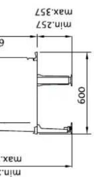
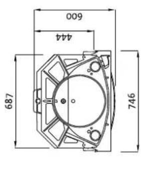
X / Y = Acc. to national regulatives and regulations.
Mälene gjelder ubehandelde produitter. Etter lakkering og emaljering kan mälene variere noe.
Dimensions refer to untreated products. After painting or enamelling dimensions may have small divergences.
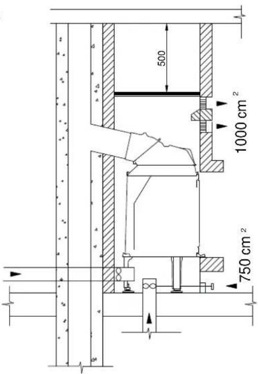
Fig. 2
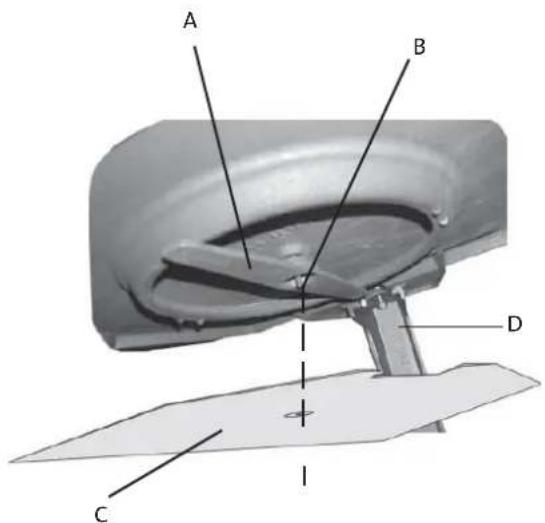
Fig. 5
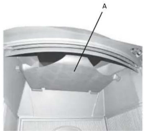
Fig. 3
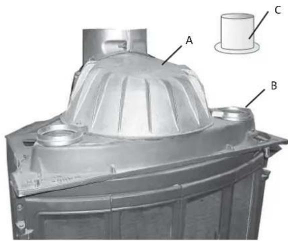
Fig. 6
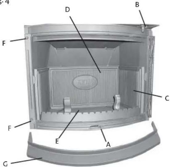
Fig.4
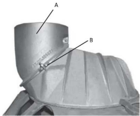
Fig. 7
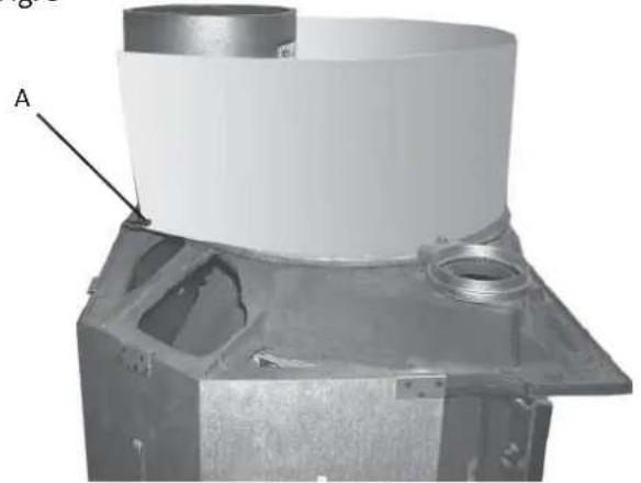
Fig. 8
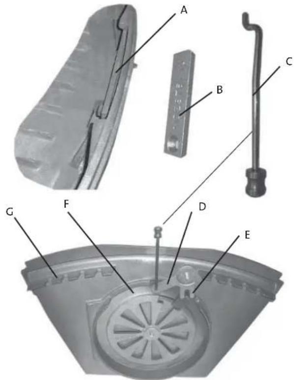
Fig. 9
Fig. 10
Checked
Utfort Kontrollpunkt Controlled item
Jøtul pursue a policy of constant product development. Products supplied may therefore differ in specification, colour and type of accessories from those illustrated and described in the brochure.
Jøtul AS has a quality system that conforms to NS-EN ISO 9001 for product development, manufacturing, and distribution of stoves and fireplaces. This policy gives our customers quality and safety piece of mind as a result of Jøtul's vast experience dating back to when the company first started in 1853.