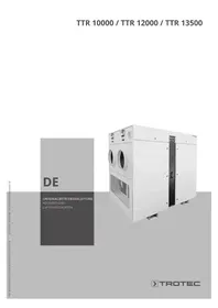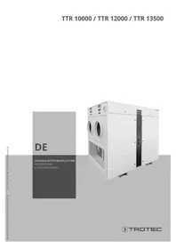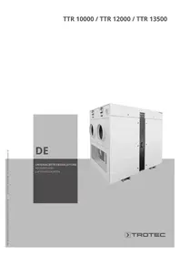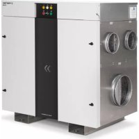
TTR 5000 - Humidifier TROTEC - Free user manual and instructions
Find the device manual for free TTR 5000 TROTEC in PDF.


User questions about TTR 5000 TROTEC
0 question about this device. Answer the ones you know or ask your own.
Ask a new question about this device
Download the instructions for your Humidifier in PDF format for free! Find your manual TTR 5000 - TROTEC and take your electronic device back in hand. On this page are published all the documents necessary for the use of your device. TTR 5000 by TROTEC.
USER MANUAL TTR 5000 TROTEC
- Please read before putting into operation.. B-1
Safety instructions B-1
- Transport and installation B-3
Transport B-3
Installation of the dehumidifier B-3
Recommended measures to be taken before starting up. .B-4
03.Description of appliance. B-4
Operating principle B-4
- Structure of the dehumidifier.. B-5
Housing frame B-5
Rotor. B-5
Drive. B-5
Rotor bearing B-5
Rotor sealing. B-5
Process and regeneration air filter. B-5
Process air fan and regeneration air filter B-5
Regeneration air heater. B-5
Thermostats B-5
Control cabinet B-5
- Operation with electric air heater B-6
Switching on. B-6
Switching off. B-6
Function of the electric air heater B-6
- Triggering of the safety devices and messages B-6
Motor faults B-6
Thermostat faults B-6
Electric heater faults B-6
Standby B-6
07.Troubleshooting B-7
- Care and maintenance B-8
Rotor. B-8
Cleaning the rotor. B-8
Removing the rotor. B-8
Rotor bearing B-8
Electric motors B-8
Air filters. B-8
Air heater B-9
Thermostats B-9
Seals B-9
General. B-9
Maintenance intervals. B-9
- Damaging effects on silica gel rotors B-9
This publication replaces all previous versions. No part of this publication may be reproduced or processed, copied or distributed via electronic means in any form whatsoever except with our written permission. We reserve the right to make technical changes. All rights reserved. Trademarks are used in the following without any guarantee of their free usability and are basically as the manufacturer describes them. The trademarks used are registered and should be treated as such. We reserve the right to make design alterations in the interests of continuing product improvement and alterations to the shape or colour. The package contents may differ from the product illustrations. This document has been prepared with the appropriate care. Nevertheless, we can accept no liability for any errors or omissions. © TROTEC®
01. Please read before putting into operation
The TTR 5000 dehumidifier has been constructed according to the current state of the art and fulfils the requirements of the applicable European and national guidelines. This conformity has been certified; the manufacturer is in possession of the relevant declarations and documents. You as a user must follow these operating instructions in order to maintain this condition and to ensure safe operation!
- This operating manual is part of the appliance and must always be kept in the immediate vicinity of the place of installation or of the appliance.
- Before using the appliance, this operating manual must be read carefully and followed in all points.
- Observe the applicable national regulations governing safety and the prevention of accidents when using the appliance.
- The appliance was subjected to extensive material, functional and quality checks before delivery. This appliance can nevertheless represent a hazard if it is used improperly or inappropriately by persons who have not been trained to operate it. Therefore please always observe the following safety instructions.
Safety instructions
- The appliance must not be used in rooms exposed to acetone, undiluted acids or solvents.
- The appliance must not be installed and used in rooms where there is a risk of explosion.
- The appliance must not be installed and used in atmospheres containing oil, petrol, sulphur, chlorine or salt.
- The appliance must be installed in a stable, upright position for operation.
- The appliance must not be exposed to a direct jet of water during operation.
- It must always be ensured that the air intake and outlet are not obstructed.
- The suction side must always be free of dirt and loose objects.
- Never insert foreign bodies into the appliance.
- The appliance must not be covered over or transported during operation.
- All electrical cables external to the appliance must be protected against being damaged (e.g. by animals).
- Extensions to the connecting cable must be selected according to the power rating of the appliance, the cable length and the purpose of use.
- Any use or operation other than that specified in this manual is not permitted. Failure to observe this will cancel any liability on our part and will result in the warranty becoming void.
Please observe the instructions in the operating manual
- The basic prerequisite for the safe handling and trouble-free operation of this dehumidifier is knowledge of the fundamental safety instructions and safety regulations.
- This operating manual contains the most important instructions required in order to operate the dehumidifier safely.
- This operating manual and in particular the safety instructions are to be observed by everyone who works with the dehumidifier.
- In addition, the rules and regulations for accident prevention applying to the place of use are to be observed.
Obligations of the user
It is the user's duty to only allow work on the dehumidifier to be carried out by persons who:
- are familiar with the fundamental regulations governing work health and safety and the prevention of accidents and have been instructed on how to handle the dehumidifier.
have read and understood the chapter on safety and the warning notices in this operating manual and have confirmed having done so with their signature. - Check the safety-conscious work methods of the personnel at regular intervals.
Obligations of the personnel
All persons assigned to work on the dehumidifier are obliged, before starting work:
- to observe fundamental regulations on work health and safety and the prevention of accidents.
- to read the chapter on safety and the warning notices in this operating manual and to confirm with their signature that they have understood them.
Dangers associated with handling the dehumidifier
The dehumidifier has been built in accordance with the state of the art and recognised technical rules. The dehumidifier is only to be used:
for its intended purpose
- if it is in perfect working order. Faults that could prejudice safety are to be repaired immediately.
Use for the intended purpose
The dehumidifier is intended exclusively for the dehumidification of atmospheric air. Any other use shall be construed as being inappropriate. Trotec GmbH will accept no liability for damage caused by such use. Use for the intended purpose includes:
- following all instructions in the operating manual and
- carrying out the prescribed inspection and maintenance work.
Warranty and liability
Our 'General terms of sales and delivery' apply as a matter of principle.
These have been available to the user since the conclusion of the con
tract at the latest. Warranty and liability claims in the case of personal injury and damage to property are excluded if due to one or more of the following causes:
- inappropriate use of the dehumidifier.
- improper installation, commissioning, operation and maintenance of the dehumidifier.
- operation with defective safety devices or when safety and protective devices are not attached properly or do not work.
- disregard of the instructions in the operating manual concerning transport, storage, installation, commissioning, operation and maintenance of the dehumidifier.
- unauthorised structural modifications.
- unauthorised changing of the technical implementation.
- inadequate monitoring of components that are subject to wear.
- repairs that have been carried out improperly.
- catastrophic events beyond human control and acts of nature.
Organisational measuresn
- The user must provide the necessary personal protective equipment.
- All installed safety devices are to be checked regularly.
Protective devices
- All safety devices must be properly attached and fully functional before each start-up of the dehumidifier.
- Protective devices may only be removed:
- after stopping the machine and
- securing it against being switched on again.
- If delivered in parts, the safety devices are to be properly attached by the user.
Informal safety precautions
- The operating manual must always be kept at the place of use of the dehumidifier.
- In addition to the operating manual, the generally applicable and local regulations for the prevention of accidents and for environmental protection must be observed.
- All safety and danger notices on the dehumidifier must be maintained in a legible condition.
Training of personnel
- Only trained and instructed personnel may work on the dehumidifier.
- The responsibilities of the personnel for installation, commissioning, operation, maintenance and repair must be clearly defined.
Dehumidifier controller
- Only instructed personnel are permitted to operate the controller.
Danger due to electrical energy
-
Work on the electricity supply may only be carried out by a qualified electrician.
-
The electrical equipment of the dehumidifier must be checked regularly. Repair loose connections and damaged cables immediately.
- The control cabinet must be kept locked at all times. Access is only allowed to authorised personnel with a key or a tool.
- If work on live parts is necessary, a second person must be in attendance to turn off the main switch in case of emergency.
Service, maintenance and troubleshooting
- The prescribed adjustment, maintenance and inspection work must be carried out at the specified intervals.
- Operating personnel must be informed before commencement of the maintenance and service work.
- All plant parts upstream and downstream of the dehumidifier and operating media such as steam must be secured against unintentional switching on.
- Switch off the dehumidifier and secure it against being switched on again for all service, inspection and repair work.
- Attach a warning sign to prevent switching on again.
- Larger subassemblies should be attached and carefully secured to lifting devices when exchanging them.
- Check loosened screwed connections for tightness.
- Check the function of safety devices after completion of the maintenance work.
Structural modifications to the dehumidifier
- The dehumidifier may not be modified or converted, nor may additional parts be attached without the manufacturer's permission. This also applies to welding on load-bearing parts.
- All conversion work requires the confirmation of Trotec GmbH.
- Machine parts that are not in perfect working order must be replaced immediately.
- Only original spare and wearing parts are to be used.
- In the case of parts procured from third parties, it cannot be guaranteed that these have been designed and manufactured to meet the load and safety requirements.
Cleaning and disposal of the dehumidifier
- Handle and dispose of used substances and materials with care, in particular
- when working on lubrication systems and devices
- when cleaning with solvents.
02. Transport and installation
Transport
The dehumidifier may only be tilted very slightly during transport. On arrival at the building site, the appliance must be checked for completeness and correlation to the delivery note as well as for possible transport damage.
Handling with a fork lift truck
Make sure that the forks are long enough to take up the entire length of the appliance, as otherwise the housing of the appliance could be damaged.
Handling with a crane
The appliance should be lifted by the lifting eyes. The tube ends or the throttle flaps may not be used as lifting points.
Installation of the dehumidifier
The following points are to be considered when installing the dehumidifier:
- The appliance must not be exposed directly to the weather.
- Ensure that the lifting device can take the weight of the appliance.
- Ensure that the intended installation surface is even and can take the operating weight of the dehumidifier. A foundation is not necessary for the dehumidifier.
- A space of at least 800mm must be kept free in front of the operating side and the inspection panels of the dehumidifier for possible maintenance work. Furthermore a space of at least the same width as the appliance must be kept free in the rotor area for exchange.
- The dehumidifier is a compact unit. The customer has to make the air, (steam) and electrical connections.
Refer to the technical data sheet for the dimensions and weight of the dehumidifier. - The connecting cables are fed through the cable glands into the switchbox and connected to the appropriate terminals.
- The electrical connection must consist of L1, L2, L3, N and protective earth. Refer to the circuit diagram in the technical appendix of this operating manual for the connections. Local regulations must thereby be observed.
- The dehumidifier has been designed such that both the air ducts and the electrical connections can be installed simply.
- The following types of installation are possible:
A. In the room to be dehumidified: The appliance operates in air circulation mode; the regeneration air outlet is to be fed to the outside.
B. Outside the room to be dehumidified: The appliance can be operated in air circulation or flow-through mode. The dry air must in this case be connected to the room to be dehumidified..
In both cases it is important to ensure that the humid air outlet is installed as far away from the process air inlet as possible.
The piping system must naturally be designed to cope with the available static pressure of the fans. Adjustable throttle flaps at the process and regeneration air outlets allow for optimum operation.
Throttled process air results in lower humidity of the dry air. Throttling the regeneration air is useful in the case of lower moisture levels.
The moist air outlet pipe must be fed away from the dehumidifier with a slight downward gradient in order to avoid condensate running into the appliance or impairing the flow of air. If a rising air pipe has to be used, then a low point with a drain must be specifically manufactured (via a siphon, if the dehumidifier is located in the room being dehumidified). The pipe should be insulated.
Recommended measures to be taken before starting up
- Have the air supply and exhaust ducts been cleaned? Are the air inlet and outlet compartments at the rotor clean?
- Are any louvered dampers that may exist in the connecting ducts open and have the transport sealing caps been removed?
- Check that the throttle flaps are seated correctly and work perfectly.
- Check that the transport locks have been removed from the fan motor.
- Turn the fan by hand, in order to make sure that it turns freely. Ensure that there are no foreign bodies in the fan housing.
- Check the tension and adjustment of the belts and correct them if necessary.
- Are all seals tightly seated?
- Are the electrical cables correctly connected to the dehumidifier (see circuit diagram)?
- Is mains voltage present and are the motor protection breakers switched on?
- Check the direction of rotation of the motor. The electric motors in the dehumidifier are connected in the factory such that the intended direction of rotation of the fan motors is ensured if the direction of rotation of the rotor is correct.
If the 'Check phases' indicator lamp lights up, correct the direction of rotation by exchanging two phases of the mains connection or make sure that all three phases are live!
- Are the service doors and side panels tightly closed?
- The dehumidifier can be put into operation once all inspections have been completed. After that, measure the voltage and current consumption and compare them to the data on the rating plate. Check and adjust the air quantities and pressures.
03. Appliance description
Trotec dehumidifiers work according to the adsorption principle and are used for solving drying tasks in process technology, in air conditioning technology and for the dehumidification of production areas and warehouses in which products and installations require particularly low humidity.
The adsorption technique permits lower dew points and more reliable dehumidification at low temperatures than is possible with cooling dehumidifiers for physical reasons. In addition, Trotec dehumidifiers are considerably more economical to use in such conditions.
The dehumidifiers are fully equipped with rotor, fans, drive motor, heater for regeneration and electrical equipment.
The moisture is adsorbed from the air using the silica gel rotor.
Operating principle
The dehumidifier works continuously with two air streams (about 3:1). The larger process air stream is dehumidified in the slowly rotating silica gel rotor (= adsorption), whilst the smaller regeneration air stream is heated, thus expelling the adsorbed water from the silica gel (= desorption).
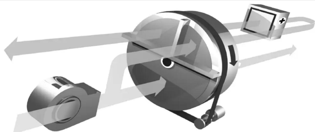
The dehumidifier is a continuously working appliance with integrated heat recovery and can achieve very low dew points. The heat energy of the hot regeneration air zone is transported by the rotating rotor into the flushing zone; the rotor cools down and simultaneously pre-heats the entering regeneration air. The result is process air that has been less heated and a lower dew point.
04. Structure of the dehumidifier
Housing framework made from welded galvanised steel section. Double-layer panel elements with sound or heat insulation, approx. 30 mm thick. The panel are set airtight into the frame construction and are removable on the operating side. All housing parts are resistant to temperature and moisture. The operating side is designed such that all maintenance work can be carried out without a problem.
Rotor (drying wheel; sorption unit)
The dehumidifier is equipped with a patented silicate rotor. The rotor is composed of layers of flat and corrugated non-woven fabric made of chemically bound silica gel and metal silicate. This creates a large number of axially aligned air ducts with a large surface area and a direct connection to the internal void structure of the silicate. This enables good transition of the water vapour and allows for the unusually high degree of adsorption of the silicate rotor.
Due to the special production process of the material, the silicate is not destroyed by saturated air. The dehumidifier can therefore be operated with pre-cooling. Even the failure of the heating or of the air stream for regeneration does not cause damage.
Accumulated dust on the rotor surface can be removed with water if the rotor is saturated. Oily deposits can be cleaned using solvents or a non-alkaline detergent.
Due to the fixed bonding of the silica gel to the substrate material, no sorbent is carried out with the air stream. Even when the rotor is at a standstill there is no over-saturation; therefore, no special safety precautions are necessary. The rotor has a high mechanical strength and is not combustible.
The rotor is driven by a geared motor via a toothed belt. A tension spring prevents the toothed belt from slipping, as well as preventing
overloading of the motor. The function and correct direction of rotation can be checked at any time through the sight glass.
The rotor bearing consists of a temperature-resistant stainless steel axle and plain bearing.
The rotor is sealed by a floating ring seal with automatic compensation.
The process air fan and regeneration fan are implemented as single-sided sucking radial fans, with an impeller installed directly on the motor shaft. Three-phase standard motor, IP54, ISO F.
The regeneration air heater is implemented as an electric element heater. It is constructed from individual chrome/nickel heating elements. The individual heating elements are electrically connected to form 3 heating stages.
alternatively:
implementation as galvanised steel steam heater. The steam and condensate connections are fed airtight out of the housing and provided with flange and counter-flange.
Thermostats function as overheating protection and safety temperature limiters.
In order to protect against unacceptably high operating temperatures, a safety thermostat and a maximum temperature limiter are mounted at the air inlet and outlet of the regeneration air heater.
A temperature limiter is mounted in the regeneration air exhaust and functions as a rotation monitor.
The control cabinet is located on the top. The indicator lamps and switches are installed in the service doors. Refer to the circuit diagram in the appendix for the individual electrical functions.
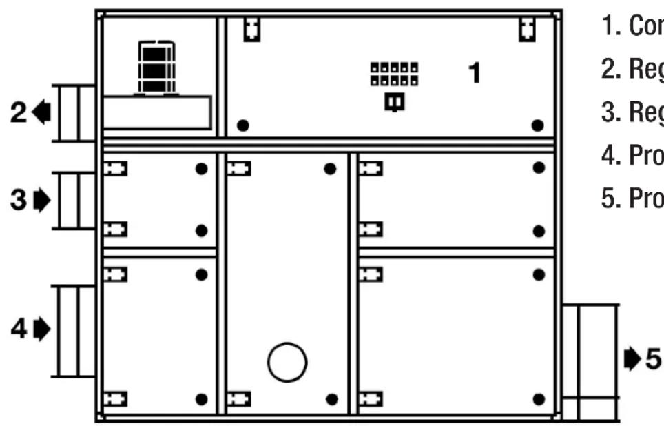
- Control cabinet
- Regeneration air outlet
- Regeneration air inlet
- Process air inlet
- Process air outlet
05. Operation with electric element heater
Switching on
- Close and lock the control cabinet doors.
- Turn main switch and „Schalter Reg. Heizung“ into position 1. „Störung Phasen“ lights up. Switch on „Drehfeld Umschaltung“.
- The 'Standby' indicator lamp lights up.
- Press the 'ON' button.
- The 'Standby' indicator lamp goes out and the 'Operation' indicator lamp lights up. If necessary switch on the „Regelstufenabschaltung“ (auxiliary heating).
All drives, including the heating, are now switched on and the dehumidifier is operating.
ATTENTION!
THE APPLIANCE WON'T START IF THE „SCHALTER REG-HEIZUNG“ IS NOT INTO POSITION 1.
Switching off
- Press the 'OFF' button.
- The 'Operation' indicator lamp goes off and the heater and the process air fan switch off. The regeneration air fan runs on for approx.
3-5 minutes, in order to exhaust the stored heat from the heater. This running-on is terminated automatically.
- it is possible to restart the dryer during running on.
- the dryer should only be switched off by the main switch installed in the mains supply line in an emergency, because this will also interrupt the running-on control and a thermostat error message can appear.
Function of the electric air heater
The heater consists of 3 individual stages. This results in an increase in the temperature of the regeneration air to approx. 120^ , which is necessary for the regeneration of the dryer. Two heating stages are always switched on as basic load stages.
If the full regeneration energy is not required for the drying procedure, then the control thermostat (5B1) switches the control stage off depending on the regeneration exhaust air temperature. The regeneration temperature is then reduced.
The thermostats are marked separately and are accessible by opening the service doors.
Factory thermostat settings
Please refer to the technical data sheet in the appendix of this operating manual.
06. Triggering of the safety devices and messages
Motor faults
If the motor protection breaker for the regeneration air fan trips due to an overload, then the dehumidifier will be switched off automatically. If the motor protection breakers for the process air fan and the rotor drive trip due to an overload, then the dehumidifier will continue in running-on mode. The 'Motor fault' indicator lamp lights up. Following rectification of the fault, the black reset button on the motor protection breaker must be pressed again and the fault must be unlocked with the reset button 4S1.
Thermostat faults
If the safety or maximum thermostat switches off due to over-temperature, then the 'Thermostat fault' indicator lamp lights up. In order to restore the standby condition of the dehumidifier after cooling down, proceed as follows:
- Press the red reset button on the maximum temperature limiter 4F2 and on the safety thermostat 4F1. Subsequently acknowledge with the reset button 4S2 on the control cabinet.
Electric heater faults
The individual heating stages of the regeneration air heater are protected by over-current trips. In the event of a short circuit or overloading, the heating stage concerned is switched off and the 'Heater fault' lamp lights up. After rectifying the fault, the black reset button on the overcurrent trip must be pressed again (unlocking).
Standby
The electrical power is connected to the dehumidifier, the rotary field of the mains supply is correct and there is no error. The dehumidifier can be switched on via button 5S1.
07. Troubleshooting
| Fault Cause Remedial action | ||
| Process air fan Regeneration air fan | - impeller loose - v-belt slipping, torn - quantity of air too large, hence overcurrent - phase missing - air pipe blocked - throttle flap closed - motor defective | - check impeller attachment - check v-belt tension - throttle the air quantity, check the rated current - check the phases - unblock the air way - check the air quantity - replace the motor |
| Rotor drive motor - phase missing - overload - motor defective | - check the phases - make the rotor passable - replace the motor | |
| Decreased or no dehumidifying performance | - filter contaminated - heater failed - process air interrupted - rotor does not turn - Seals do not seal correctly - changed air quantities - changed regeneration temp. - pre-cooling (pre-dehumidification) failed - air leaks | - replace filters - check fuses or SD feed - check air ways, throttle flaps - check belt tension - check seating of seal - measure the air quantity - check regeneration temp. - check pre-cooling - close and seal panels |
| Maximum temperature limiter | - air quantity too small on the regeneration side - filter contaminated - duct blocked - Throttle flap closed too far | - set regeneration air quantity to nominal value - clean or replace filters - check air ways |
| Safety thermostat - air | way on the regeneration side interrupted - throttle flap closed - fan failed | - unblock the air way - check the air quantity |
| Appliance cannot be started | - no mains voltage - no control voltage - phase monitor has triggered | - check the phases - measure the continuity of the control transformer and micro-fuse - exchange the phases |
| Fans fail to turn - Motor | safety switch activated; air flow volume too great resulting in excess current - Electrical connection - interrupted - V-belt slips - V-belt torn - Phase missing - Propeller not fastened - Motor defective | - Check air volumes and rectify - Check setting of motor safety switch - Check electrical connection and reconnect - Tighten V-belt - Replace V-belt - Check phase - Fasten propeller - Replace motor |
| metallic sound, rattling | - Fan propeller not properly fastened - Fans turn in wrong direction - V-belt or chain of the rotor drive system is defective and slips | - Check process air and standard air fan - Change direction of fans - Check V-belt / chain tension - Check tooth washer / sprocket and catch (at rotor perimeter) for damage - Check rotor to see if moveable, change bearings if necess |
08. Care and maintenance
CAUTION!
THE DEHUMIDIFIER IS TO BE SWITCHED OFF BEFORE COMMENCING WITH MAINTENANCE WORK OR INSPECTIONS AND IT MUST BE ENSURED THAT NO UNAUTHORIZED SWITCHING ON OF THE APPLIANCE CAN TAKE PLACE, EITHER LOCALLY OR FROM THE CONTROL ROOM.
All service doors are provided with cabinet bolts, which can be opened with appropriate tools.
There are several safety rules that must always be obeyed when servicing the dehumidifier:
- The technician must be electrically insulated from the appliance using insulating boards, rubber mats or the like.
- All electrical parts must be disconnected from the mains before working on the appliance.
The length of the maintenance intervals depends on the cleanliness of the environment as well as on the actual duration of operation of the dehumidifier. Above all, it should be borne in mind that the fans are designed to pump a certain quantity of air with a certain pressure, and that everything that changes the operating point of the fan, e.g. clogged filters, dirty heat exchangers or the like, limits the efficiency of the dehumidifier, because the actual conditions deviate from the design conditions
Rotor (drying wheel)
A dirty rotor can be cleaned by the customer. The prerequisite is strict adherence to the described procedure. If this is not adhered to, there is a danger of mechanical damage to the rotor and, hence, a reduction of the sorption capacity.
Cleaning of the rotor
The rotor installed in the Trotec dehumidifiers has an advantage over other rotors in that dust and dirt can be washed out without loss of sorption capacity. Re-impregnation is not necessary.
The washing procedure, as described below, is not intended to be part of normal maintenance. It is recommended to have this work carried out by Trotec service or in any case to inform a Trotec service office before cleaning. Never use a strongly alkaline cleaning agent, since this can destroy the rotor.
Removing the rotor
- Switch off the heater and let the dehumidifier run for approx. 30 minutes without regeneration.
- Switch off the dehumidifier and secure it against being switched on again.
- Remove the rotor drive from the wheel compartment. If necessary in order to do this, disconnect the electrical supply cable to the motor in the motor terminal box and insulate it electrically until reconnection.
-
Push back the radial sealing strips.
-
Push a timber plank or similar under the rotor to support it in order to avoid sagging when the rotor axle is removed.
- Loosen the rotor axle at the bearing. 'Caution: danger of the rotor sagging'.
- Carefully 'remove' the rotor from the compartment.
CAUTION
- danger of damaging the rotor surface and the circumferential seals
- secure the rotor against inadvertently rolling out; never set the rotor down with a jolt
- see separate instructions
- Bathe the rotor for approx. 30 minutes in water containing a weakly acidic cleaning agent or in toluene.
- Rinse out the rotor with fresh water under light pressure.
- Allow the liquid to run out of the rotor and blow the structure of the rotor free using compressed air at a low pressure.
- Carefully install the rotor together with the drive.
at 2. Make sure that all seals are seated correctly. - Start up the dehumidifier and measure the performance after applying a mini- prox. 30 minutes.
Rotor bearing
The rotor is supported by means of a plain or ball bearing on a stainless steel axle, which is bolted in the centre of the housing at both ends. The plain bearings are maintenance-free and it must be checked once per year that they are seated firmly.
Electric motors
The electric motors are equipped with ball bearings. According to the motor manufacturer, the grease packing of these bearings is sufficient for approximately 20,000 hours of operation, after which they should be renewed. The electric motors are to be checked once per year for running noises and replaced if necessary.
Air filters
The frequency with which the filters have to be cleaned or replaced is difficult to determine, because it largely depends on the filter and on the contamination of the air. In any case a monthly inspection is recommended. After start-up it can be assumed that the filters will clog up fairly quickly, because there is still dust in the ducts. The filter elements can be equipped with a differential pressure indicator, so that the contamination of the filters can be monitored as a function of the increase of the pressure loss. Pocket filters must be replaced when the permissible pressure loss limit value is reached.
Our recommendation:
The filters should be replaced when the pressure loss has increased by 150 Pa compared to the value of a new filter.
The dehumidifier should never be put into operation without air filters. Dirt deposits in the drying wheel can lead to decreased drying performance!
Air heater
The heat exchangers are maintenance-free; however, they should be checked for contamination every 6 months and cleaned if necessary. In case of a defect the complete heat exchanger unit can be removed after removing the housing panel.
Thermostats
The electrical switching function is to be tested once per year. If a thermostat is defective it must be replaced completely.
Seals
The circumferential and radial seals are to be checked regularly for tightness (correct seating), damage and dirt.
General
In order to ensure perfect functioning, the air dehumidification centre should be checked annually for damage, wear or leakage.
Maintenance intervals
| Filters | Rotor bearing | Motors | Geared motor | Air heater | Seals | Thermostats | V-belts | |
| As necessary | X | X | ||||||
| Monthly | X | |||||||
| Half-yearly | X | X | ||||||
| Annually | X | X | X |
09. Damaging effects on silica gel rotors
Some of the substances and compounds listed below are typical of substances which can dissolve the honeycomb shaped silica gel rotors thereby negatively affecting the dehumidification performance.
The sorption rotor should not be exposed to air which is contaminated with the following substances or substances that are similar to them. Even the smallest of concentrations in the air can have long-term damaging effects on the material of the rotor and the sorption capacity.
The substances in the list remain in the sorption material and can have the following effects:
- Drop in performance due to blocked silica gel pores
- Drop in performance due to chemical reaction with the silica gel
- Destroys the mechanical structure of the rotor through strong acids or strong bases
Anorganic substances (example)
| No. | Substances | chem. Formula | Effects |
| 1 | Lithium chlorid | LiCl | Reduction in the effectiveness of the silica gel1) |
| 2 | Sodium hydroxide | NaOH | Destroys the silica gel structure |
| 3 | Calcium hydroxide | KOH | Destroys the silica gel structure |
| 4 | Sodium chloride | NaCl | Reduction in the effectiveness of the silica gel1) |
| 5 | Calium chloride | KCI | Reduction in the effectiveness of the silica gel1) |
| 6 | Calcium chloride | CaCl2 | Reduction in the effectiveness of the silica gel1) |
| 7 | Magnesium chloride | MgCl2 | Reduction in the effectiveness of the silica gel1) |
| 8 | Magnesium chloride | NH3 | Destroys the silica gel structure |
| 9 | Hydroflouric acid | HF | Destroys the mechanical strength of the rotor material |
| 10 | Aluminium chloride | AICI3 | Reduction in the effectiveness of the silica gel1) |
| 11 | Sea water | Reduction in the effectiveness of the silica gel1) | |
| 12 | Steam at high temperature | Destroys the silica gel structure | |
| 13 | Softeners | Blocks the silica gel pores | |
| 14 | Strong acids | ph ≤ 2...3 | Destroys the mechanical strength of the rotor material |
| 15 | Bases | ph ≥ 7...8 | Destroys the sorption capacity of the silica gel |
| 15 | Amines | R-NH2 | Reduction in the effectiveness of the silica gel1) |
Note: 1) Reduces the inner surface of the silica gel pores, which results in a loss in performance.
Organic Substances (example)
The solvents and volatile substances listed below have a high boiling point and a low vapour pressure. If they are absorbed by the silica gel, then they will remain in the material over a longer period.
| No. | Substance chem. Formula Effects | ||
| 1 | Oil mist Blocks the silica gel pores | ||
| 2 | Cyclohexanone C6H10 Reduction in the effectiveness of the silica gel | 1) | |
| 3 | Isopropyl Alcohol | (CH8)2CHOH | Reduction in the effectiveness of the silica gel1) |
| 4 | o-xylene | C6H4(CH2)2 | Reduction in the effectiveness of the silica gel1) |
| 5 | m-xylene | C6H4(CH2)2 | Reduction in the effectiveness of the silica gel1) |
| 6 | p-xylene | C6H4(CH2)2 | Reduction in the effectiveness of the silica gel1) |
| 7 | Phenol C6H5OH Reduction in the effectiveness of the silica gel1) | ||
| 8 | O-dichlorobenzene | C6H4CL2 | Reduction in the effectiveness of the silica gel1) |
| 9 | Methyl bromide | CH3Br | Reduction in the effectiveness of the silica gel1) |
| 10 | Glycerine | C3H8O3 | Reduction in the effectiveness of the silica gel1) |
Note: 1) Reduces the inner surface of the silica gel pores, which results in a loss in performance.
Table des matieres
08.Bakim D-8 Rotor D-8
Kommission/Commission
Type / Type
m = 311
2 : x^ ( x) = 0. .