COCKPIT SX 12 MLINK - Remote control toy MULTIPLEX - Free user manual and instructions
Find the device manual for free COCKPIT SX 12 MLINK MULTIPLEX in PDF.

| Product type | Radio-controlled toy |
| Brand | MULTIPLEX |
| Model | COCKPIT SX 12 MLINK |
| Number of channels | 12 |
| Memory locations | 200 |
| Temperature range | -10...+55 °C |
| Connection type | M-LINK |
| Antenna | IOAT |
| Frequency | 2400...2483,5 MHz |
| Power supply | Accu LiFe 3,3 V / 4000 mAh |
| Total weight | Approx. 867 g |
| Dimensions | Approx. 190 x 210 x 60 mm |
| Touchscreen | Yes, 5 status displays |
| Main functions | Model programming, telemetry, mixing, flight phases, SAFE-LINK, MULTIGYRO CSX, teacher/pupil/simulator mode |
| Maintenance | No special maintenance; cleaning with soft brush and damp cloth; servicing recommended every 2-3 years by authorized service center |
| Safety | Safety instructions, Gas-Check, fail-safe, range test |
| Spare parts and accessories | Transmitter strap, pouch, case, Copilot, decals |
| Warranty | According to legal provisions; excludes damage due to improper use, modifications, wear and tear |
| Repairability | Update via MULTIPLEX Launcher; repair by authorized MULTIPLEX service center |
| Charging power supply | Via Mini-USB cable (PC, power bank) or USB charger 12V/100-240V |
Frequently Asked Questions - COCKPIT SX 12 MLINK MULTIPLEX
User questions about COCKPIT SX 12 MLINK MULTIPLEX
0 question about this device. Answer the ones you know or ask your own.
Ask a new question about this device
Download the instructions for your Remote control toy in PDF format for free! Find your manual COCKPIT SX 12 MLINK - MULTIPLEX and take your electronic device back in hand. On this page are published all the documents necessary for the use of your device. COCKPIT SX 12 MLINK by MULTIPLEX.
USER MANUAL COCKPIT SX 12 MLINK MULTIPLEX
text_image
MULTIPLEX MADE IN GERMANY COCKPIT SXtext_image
a f e Multiplex® COCKPIT SX c b d CE 0682text_image
Grid of nine icons including folder, airplane, beer mug, clock, and person with Chinese labelsbar
| Category | Schalter | Toggle | |---|---|---| | X | Orange | Red | | Y | Orange | Green | | Z | Orange | Red | | Ax | Orange | Blue | | Ay | Orange | Red | | Az | Orange | Red | | X | Blue | Blue | | Y | Blue | Blue | | Z | Blue | Blue | | Ax | Blue | Blue | | Ay | Blue | Blue | | Az | Blue | Blue | | X | Yellow | Yellow | | Y | Yellow | Yellow | | Z | Yellow | Yellow | | Ax | Yellow | Yellow | | Ay | Yellow | Yellow | | Az | Yellow | Yellow | Seite 2 / 2natural_image
Red and black striped strap with 'MOLTS' branding, no visible text or symbols on the strap itselfnatural_image
Black multiflex branded bag with handle and strap (no visible text or symbols on bag body)natural_image
Close-up of a black audio jack with a strap and cord (no text or symbols visible)8 5071 Ohrhöhrer
7 5308 Knüppelgriffe Alu lang
text_image
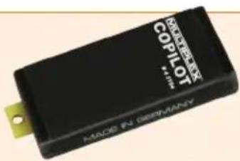
RAKTI KON COPILOT MADE IN GERMANY4 5184 COPILOT Baustein
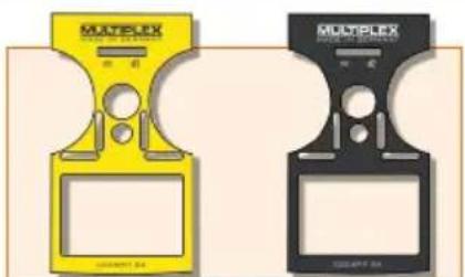
72 4404 Senderdekor gelb SX 7/9
72 4403 Senderdekor carbon SX 7/9

natural_image
Green-tinted trophy with a blank plaque, no visible text or symbols72 4408 Senderdekor grün SX 7/9
natural_image
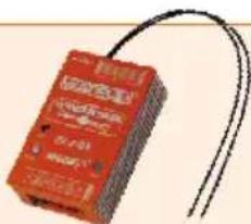
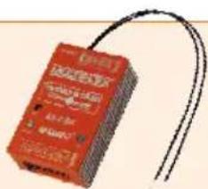
Red electronic device with wires, no visible text or symbols on body55012 WINGSTABI-RX-7-DR M-LINK
55013 WINGSTABI-RX-9-DR M-LINK
text_image
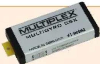
MULTIPLEX MULTIGYRO CSX MODEL BY: SMM/CMX #1-009241-00092 MULTIGYRO CSX
text_image
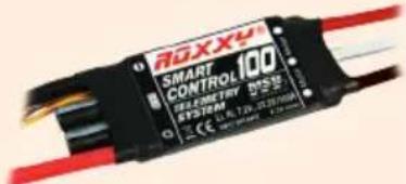
300XX4 SMART CONTROL 100 SELECTOR T2550 STSSDM CE: L. R. 720, JT 287/666 100VROXXY SMART Control MSB 45 / 70 / 100
text_image
EPA METER E...MILK 100A 400A Q112 3.0V EPA METER E...MILK 100A 400A Q112 3.0V EPA METER E...MILK 100A 400A Q112 3.0V85419 LiPo SAVER 2...6S - 60A
85421 LiPo SAVER 2...6S
- Introduction ...... 25
1.1. Guarantee and limitation of liability 25
1.2. CE declaration of conformity 25
1.3. Disposal 26
1.4. Safety information 26
1.5. Other instructions and checks 27 - Specification 27
- Power supply and charging 28
- Operating elements ...... 28
- The transmitter from below 29
- Switching on for the first time 30
- Creating a model 30
-
Touch-screen 33
-
Main menu 34
- Screen lock 35
- Keypad 36
- Telemetrie / WINGSTABI 36
- SAFE-LINK 37
- MULTIGYRO CSX 38
- Example: 4-flap glider ..... 39
- Free mixers 43
- Trainer / Simulator mode 45
- Update 46
- Care and maintenance 46
- Recommended accessories 47
- Advice and technical support 47
1. Introduction
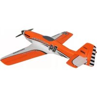
Congratulations on purchasing your new RC set, we are delighted you have chosen the MULTIPLEX COCKPIT SK M-LINK. You are holding the ideal equipment for getting into the hobby of flying remote controlled models. We hope you enjoy it and wish you the best of luck with your new equipment.
1.1. Guarantee and limitation of liability
MULTIPLEX Modellsport GmbH & Co.KG does not assume any liability for loss, damage or costs which arise through the improper use and operation of our products, or which are connected with such operation in any way. As far as is legally permissible, the obligation of MULTIPLEX Modellsport GmbH & Co.KG to provide compensation for damages, on whatever legal basis, is limited to the invoice amount of the quantity of MULTIPLEX Modellsport GmbH & Co.KG goods that were directly affected by whatever incident gave rise to the damage. This does not apply if MULTIPLEX Modellsport GmbH & Co.KG is obliged to accept unlimited liability in accordance with mandatory law for deliberate or gross negligence.
Our products are covered by the currently valid statutory guarantee regulations. If you wish to make a claim under guarantee, please contact the model shop where you purchased the product.
The guarantee does not cover malfunctions caused by the following:
· proper Operation
- Maintenance that was performed incorrectly, late or not at all, or performed by a non-authorized body.
- Incorrect connections.
- Use of non-original MULTIPLEX accessories
- Modifications/repairs that were not carried out by MULTIPLEX or a MULTIPLEX Service Centre.
- Accidental or deliberate damage.
- Faults due to normal wear and tear.
- Operation outside the technical specifications or in connection with components from other manufacturers.
1.2. CE declaration of conformity
The device was evaluated according to directives harmonized with European legislation. You are therefore in po session of a product whose construction satisfies the protection objectives of the European Community for the safe operation of devices. You can find the exhaustive CE declaration of conformity as a PDF document online at www.multiplex-rc.de in the DOWNLOADS section under PRODUKT-INFOS.
1.3. Disposal
Electrical and electronic equipment which has the crossed out wheelie bin symbol should not be disposed along with household waste, but rather via a suitable disposal system. In countries belonging to the EU (European Union), electrical or electronic equipment may not be disposed of along with general household waste (WEEE - Waste of Electrical and Electronic Equipment, Directive 2002/96/EC).
You can dispose of your old equipment at public municipal collection points (e.g. recycling facilities) free of charge. The equipment will be properly disposed of free of charge here. By returning your old equipment, you are making a valuable contribution towards environmental protection!
GB
1.4. Safety information
- Remote controlled models and equipment are not toys in the conventional sense. Setup, installation of the RC equipment and operation require technical understanding, care and safety-conscious responsible behavior. Errors or negligence could have significant damage as a consequence. As the manufacturer or salesperson has no influence or control over proper setup and operation of the model, we are expressly referring to these dangers and excluding any liability. - In order to operate your model safely, please adhere to the following safety instructions without fail; you are responsible for the safe deployment of your product:
- Please read these instructions carefully! Please do not use the equipment before you have carefully read these operating instructions and the following safety instructions.
- Under no circumstances must you make any technicalmodifications to the RC equipment. Only use original accessories and replacement parts, receivers and servos.
- If you are using this equipment in combination with products from other manufacturers, please ensure that the quality and functionality of these products has been verified. Every new or modified setup must undergo a careful functionality and range test. Do not launch the equipment or model if something doesn't seem right. First look for malfunctions and eliminate them.
- A model which has for whatever reason gotten out of control can cause significant damage or injury. Liability insurance is therefore a requirement in order to operate any model. Please be sure to bear this in mind, and be aware of the relevant regulations.
· Always observe the sequence for switching on and off, in order to ensure that there is no uncontrolled and dangerous start-up of the motor:
- When switching on: Always switch on the transmitter first, then plug in the flight battery or switch on the receiving system.
- When switching off: Always disconnect the flight battery or switch off the receiving system before switching off the transmitter.
- Have receivers and particularly RC transmitters checked at regular intervals (every two to three years) by an authorized MULTIPLEX service center.
- Only operate the transmitter within the permitted temperature range between -15 and 55 °C. Please note that sudden changes in temperature from cold to warm can cause condensation water to be deposited on the transmitter. Moisture impairs the functionality of the transmitter and other electronic equipment as well.
- In case of moisture in electronic equipment, halt operation immediately, disconnect the power supply and leave the equipment to dry in as open a position as possible (for up to several days). Then carefully perform a functionality test. In severe cases, have your equipment tested by an authorized MULTIPLEX service center.
· Perform a range test and set the failsafe (see section 7.7).
1.5. Other instructions and checks
- Build your model carefully, this applies above all to any necessary repairs to your model. You are responsible for your own actions.
- Attach the servos and aileron pushrods in such a way so that the ailerons move smoothly and do not jam when fully deflected.
- Adjust the output arms and pushrods accordingly. Keep the backlash as small as possible. This is the only way to ensure that there is no undue strain placed on the servo and therefore to make sure that its performance is fully utilized. These measures ensure the servo has a maximized lifespan and guarantee the highest degree of safety.
- Protect the receiver, batteries, servos and other RC components effectively from vibrations. Follow the instructions given in these operating instructions. This especially involves correctly balancing propellers and rotors. Replace damaged parts or parts which are not running correctly balanced.
- Do not stretch or kink the cable and protect it from rotating parts.
- Avoid using unnecessarily long or superfluous servo extension leads and ensure a sufficient cable cross section (voltage loss). A benchmark of at least 0.24 ~mm^2 is recommended. For digital servos in the 79xx, 8xxx or 9xxx model ranges, we would even recommend 0.33 ~mm^2 .
-
Avoid interference pulses caused by static charges and strong electric or electromagnetic fields by taking appropriate interference suppression measures (e.g. by suppressing the electric motor with a suitable capacitor) and ensure sufficient distance is maintained between the RC equipment, receiver aerial, wiring and batteries.
-
Ensure sufficient distance is maintained between wires carrying high currents (e.g. electric motor) and the RC equipment. The wiring between the brushless e-motors and their actuators in particular must be kept as short as possible (benchmark max. 10 to 15 cm).
- Carefully check all functions and familiarize yourself with the operation of the transmitter before launching the model.
- Check ease of motion and no play of the ailerons and rotor linkages.
- Ensure stability and flawless condition of pushrods, rotor linkages, hinges etc.
- Check model for breakages, flaws and shear edges on any of the RC components or on the motor.
- Ensure flawless condition and contact safety of wires and plug connections.
- Check the condition of the power supply and its wiring including switch harnesses by inspecting the exterior of the cells. This also involves employing a charging procedure which is appropriate for the battery type with a suitable charger and regularly carrying out maintenance on the battery.
2. Specification
| Channel number 7 - Cockpit SX 79 - Cockpit SX 912 - Cockpit SX 9 |
| Model memory 200 |
| Transmission mode -10...+55 °C |
| Übertragungsart M-LINK |
| Aerial IOAT |
| Frequency 2400...2483,5 MHz |
| Power supply LiFe battery 3,3V/4000 mA |
| Total weight approx. 867 g |
| Dimensions approx. 190 x 210 x 60 mm |
3. Power supply and charging
The COCKPIT SX is supplied with power from a robust, long-lasting LiFePO battery. The battery is installed together with the battery management system electronics. When new, the over 4000 mAh supplied by the battery are sufficient to provide a remarkable service life. Additional components increase the power consumption and decrease the service life. Temperatures of under -10°C significantly decrease the service life.
The transmitter battery is responsible for supplying power to this equipment and therefore significantly contributes to operating safety.
GB
Charging Procedure
Connect the mini USB cable supplied with delivery to the multifunction socket. The socket is on the back of the transmitter below the speaker. Switch on the transmitter. Connect the other end either
- with the USB cable via your PC or laptop, the charging current here is 500mAh. (charging occurs to a maximum level of 2000mAh)
- or with the USB 12V DC plug-in charger for power-driven vehicles from MULTIPLEX # 14 5533. (charging current approx. 1500mAh)
- or with the USB plug-in charger 100-240V AC from MULTIPLEX # 14 5534. (charging current approx. 1500mAh)
Then switch on the transmitter. In the display, select "Switch off and charge" and confirm the charging process with "o.k.". The charging procedure begins, and is indicated by the Corona's continuously rotating red LEDs.
The Corona indicates that the battery is fully charged by changing to a continuous orange light.
Safety shutdown:
After a total of 4 hours, the charging procedure is completely stopped in order to prevent external devices (e.g. power bank/laptop) from being drained.
So when charging via your PC or laptop, charging occurs up to a maximum level of 2000mAh. After this time, the Corona's LEDs go off completely.
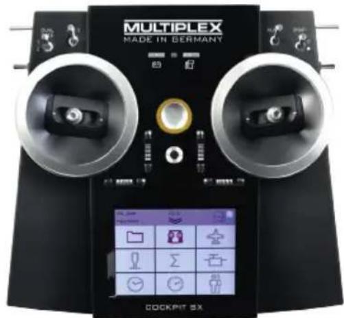
4. Operating elements
The following operating elements can be found on the front:
a. On/off switch
Activate transmitter by briefly pressing the on/off switch.
- flashes orange (transmitter is working and you are in the main menu)
- flashes red (Range checking / charging / updating)
- lights up red (transmitter is not receiving, USB mode) The transmitter is switched off by holding the On / Off switch pressed in until the corona (ring-light) goes out.
b. The two ergonomically arranged joysticks with the corresponding trim buttons
c. D/R switch for Dual Rate 1/2
d. Aux 3 - free 3-position switch (COCKPIT SX9 /12 only)
e. Aux 4 - free 3-position switch (COCKPIT SX9 /12 only)
f. 2-position switches for Snap Flap
text_image
MULTIPLEX MADE IN GERMANY COCKPIT SXg. LED with gas pump symbol for warning via telemetry when the residual battery capacity gets below a certain threshold (as defined in the power sensor)
h. LED with battery symbol for the telemetry - receiver voltage
4. Operating elements
The following operating elements can be found on the left hand side:
a. 2-position switch CS/A-Red (switch for Combi-Switch/Autorotation)
b. Teacher-Vario button for trainer mode and status enquiry
c. Aux 5 - free 3-position switch (COCKPIT SX 12 only)
The following operating elements can be found on the right hand side:
a. 3-positions switch Phase/Aux 2 (for flight phases or as a free 3-positions switch
b. T-Cut (EMERGENCY-throttle-CUT button)
c. Aux 6 - free 2-position switch (COCKPIT 12 only)
The following operating elements can be found on the back:
a. Rotary knobs for spoilers or throttle limiter (T-LIMIT)
b. Rotary knobs for FLAP/Aux 1
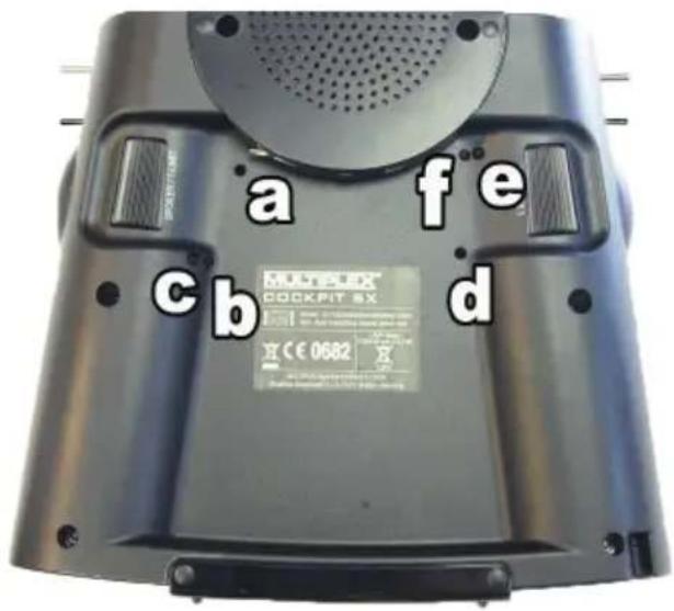
5. The transmitter from below
The housing of the COCKPIT SX is screwed together and does not have to be opened to adjust the spring tension of the stick or to define the throttle stick.
Adjusting screws for the right stick
a. Deactivate tension spring on the stick (stick centring)
b. Adjust stick ratchet
c. Adjust stick sensitivity
Adjusting screws for the left stick
d. Deactivate tension springs on the stick (stick centring)
e. Adjust stick sensitivity
f. Adjust stick ratchet
The appropriate adjusting tool can be found in the left compartment, below the loudspeaker.
The screws can be reached through openings in the base of the transmitter. The following diagram shows the positions of the various adjusting screws.
text_image
a fe MATELX COCKPIT SX c b d H C€ 0682Important: loosen/tighten screws carefully!
Turn the stick adjusting screws carefully and don't unscrew them too far, if you want to reverse your adjustments for stick centring, ratchet or stiffness again. Otherwise, the screws could press against the base of the transmitter on the inside.
Deactivate the stick centring spring as follows:
Turn screw a (right stick) or d (left stick) clockwise until the stick no longer springs back even at its most extreme position.
Adjusting the ratchet:
Turn screw b (right stick) or f (left stick) clockwise until the strength of the ratchet corresponds with your perceptions.
Adjusting the stiffness:
Turn screw c (right stick) or e (left stick) clockwise until the stiffness corresponds with your perceptions.
The touchscreen pen for operating the display can be found in the slot at the bottom on the right, as shown in the diagram under section 5.

6. Switching on for the first time
Switching on:
The transmitter is activated by briefly pressing the On / Off switch. The first time you switch the transmitter on, it will start in the Basic Settings menu.
In this menu you can start by personalising your transmitter and selecting your preferred language. You should also select the side of the transmitter on which the throttle / spoiler
control is to be located.
When you are satisfied, press the arrow button at bottom right to accept the settings; you are then moved on to the Model Assistant.
At this point you can set up a new model with the help of the Assistant.
GB
7. Creating a model
The easiest way to create a new model is by using the "Assistant".
1. Start the assistant
Under model type, select the one which is best suited to your model. Specify a name and file path for your new model and confirm using the arrow key on the keyboard in the display.
2. Model type selection
The model types are broken down as follows:
a. Easy
Template for a simple power model aircraft (e.g. Easystar) without flight phases.
- Aileron with mixable inputs for landing flaps (spoilers), flaps (warping), elevator (snap flap)
- Combi switch (linkage aileron -> elevator/elevator -> aileron)
- Elevator/alternatively
V-tail with mixable inputs to avoid unwanted side effects/compensation of flaps (warping), spoilers (landing damper function) and throttle.
- Channels 1-5 have already been permanently assigned in order to ensure simple programmability.
b. Acro
The Acro template is the template for the classic aerobatic planes and trainers (fun-cub, Funman, Extra....) In addition to the functions listed under Easy, it is also possible to use three flight phases. The servos can be freely assigned. On the mixers (aileron and elevator), the flap mixer input has been consciously deactivated.
C. Glider
The glider template also provides all the necessary functions for gliders as well as those provided by the Easy and Acro:
- Three flight phases
- Two-, four- or six-flap wing
(= two ailerons + four flaps/camber-changing flaps) with mixable inputs for landing flaps (spoilers) e.g. the butterfly
function, flaps (warping), elevator (snap flap), offset for offset linkage of the elevator and V-tail.
• The servos can be freely assigned.
d. Delta
- Two-, four- flap Delta
- Three flight phases
- Delta mixer for classic jets/deltas/flying wings
- Unrestricted servo assignment
e. Helicopter
- Four flight phases
· 90 degree flybarless (unmixed)
· 120 degree mixed - Trims which can be switched off for gyros
- Nine point throttle/nine point pitch curve
- Unrestricted servo assignment
f. Multicopter
- Four flight phases
- Four multicopter main window functions
- Nine point throttle/nine point pitch curve
- Unrestricted servo assignment from the remaining transmitter controls/switches
3. Delta/V-tail models
We have come up with something special to save you a lot of time and effort adjusting settings.
Setting the direction of rotation of the servos on delta and V-tail models is child's play. To do this, all you have to do is test through all eight possible combinations for type/variant, until the elevator and aileron function is working as desired.
7. Creating a model
- Use the arrow to go to the next menu "Model type" and select the tail type.
- Use the arrow > to go to the next menu "Model settings" and program the relevant settings in here as well.
Please note: Throttle trim
To trim the throttle, always use the trim button next to the THROTTLE/SPOILER stick, even if the throttle is controlled by another transmitter control.
Please note: Set throttle check
What is a throttle check?
A throttle check is a safety request from the throttle operating element. This function prevents motors from starting up on their own and endangering or even injuring you or others. The level of safety when operating the model is increased.
How does the throttle check work?
If the throttle check function is activated, the transmitter checks if the throttle control is in neutral every time it is switched on and when the model memory is switched. If this is not the case, an acoustic warning signal is emitted. The throttle channel is only released after the throttle stick has been moved into the neutral position. When creating a new model, the throttle check is always activated.
6. Use the arrow to go to the next menu
Define the "control assignment" and the desired stick and switch assignment.
- Use the arrow ▶ to go to the next menu "M-Link settings", where you can perform the following actions:
· Binding
The binding procedure binds the receiver to the transmitter. After pressing the "Start" button, binding is active. The Corona on the transmitter flashes rapidly. Now switch on the receiver with the set button pressed (insert the power supply). The LED on the receiver flashes rapidly. The binding should be complete after a few seconds, and then the transmitter and receiver flash slowly again. The servos connected to the receiver can now be controlled.
- Range test
In the M-LINK settings menu (see section 7), the range test will be carried out regularly. After pressing the "Start" button, the range test is active. The transmitter performance is heavily reduced during this procedure. The range test can therefore be carried out without a big distance between the transmitter and the model. By pressing the "Stop" button, the range test is halted. You should be able to control the model at a distance of between 60 and 100 meters (de-
pending on receiver type). Please refer to the receiver instructions for the precise distance.
- Program failsafe
Failsafe is the servo positioning which should be used whenever there is a loss of reception. The current servo positions are saved in the receiver. To save, proceed as follows:
- Move the servos (aileron) on your model to the desired positions using the corresponding COCKPIT SX controls.
- After pressing the "Start" button, the current positions are saved. This can also be viewed on the display. The "Start" button is then visible again.
- Check the failsafe function by switching off the transmitter.
·SAFE-LINK
At this point you can activate what is known as the SAFE-LINK function. If you wish to use this feature please read the instructions in Chapter 13.
- Use the arrow to go to the next menu "Servo settings".
- Select the relevant servo in the top field In the next three fields, you can set the servo values. In the top and bottom fields, you can set the respective end positions, and the neutral position in the middle field.
There are three options here:
- The - and + buttons
- Tap on the middle of the value to open the character and number field. The current value can be deleted and a new one entered.
· using the graphic display:
a) the neutral position can be adjusted by sliding the middle point
b) by sliding the two outside points, the end position can be set accordingly
Please note: Throttle servo/regulator is not functioning "properly"
If you have chosen a neutral position, but your model's motor gives maximum power in this position, you need to reverse the polarity on the throttle servo (the neutral position must stay where it is, so that THR-CUT (= throttle cut) and throttle check run correctly and the throttle is mixed properly in the elevator!
7. Creating a model
9. Use the arrow to go to the next menu "Mixer". What is a mixer?
When we say mixer, we mean when not just the basic function (e.g. elevation) but also additional controls (e.g. throttle) can control the servo. Example: Your model gains altitude on its own accord when the throttle is increased. This can be compensated by mixing the throttle in the elevator. The elevator is therefore controlled by the THROTTLE and the ELEVATOR.
GB
- Mixing in the elevator
Undesired climb/descent when operating throttle, spoilers or flaps can be compensated for. Elevation is the main input and is controlled by the ELEVATION stick. The other three inputs are mixed and controlled by the THROTTLE, SPOILERS and FLAPS. The result of the mix goes to the elevator.
- Select flaps, spoilers or throttle
- Set the desired values using the - and + buttons or
- Tap on the middle of the value to open the character and number field. The current value can be deleted and a new one entered.
- Mixing the aileron
The aileron mix is done in the same way. Here, there are five options:
- Aileron (aileron mix - for aileron differential)
- Elevator (aileron mix - snap flap) mixing the aileron with harder settings acting as a braking function
- Flaps (aileron mix - flaperon) use aileron as "flaps", with the possibility of extending them upwards
- Spoilers (aileron mix - half butterfly) mixing the ailerons with the flaps
- Offset (aileron offset) the current mixer values are shown in the display.
Hint: You will find more details on the various mixer functions in the section entitled "Example: 4-flap glider".
10. Use the arrow ▶ to go to the next menu "Control settings".
- Select the relevant servo/function in the top field. Inside the next three fields, you can set the dual rate and exponential values.
- Tap on the middle of the value to open the character and number field. The current value can be deleted and a new one entered.
The current setting is shown on the graphic display.
Finally, press "Save", and the menu switches to the timer menu and you have successfully programmed your first model.
Hint: You will find more details on the various transmitter control settings in the section entitled "Example: 4-flap glider".
Note on using the flight phases:
When flight phases are active it is possible - and necessary - to set up and adjust all mixers and transmitter controls separately for each flight phase. Select each one of the flight phases in turn using the flight phase switch "PHASE", and set the values appropriately.
Please refer to the section entitled "Keypad".
Example: If you have programmed aileron in the flaps upon starting or during normal flight, you need to then also enter these values for the landing flight phases as well.
Please note: Cancel or back
If you select the wrong model by mistake or have made a mistake when entering the settings, you can cancel the programming at any time or, using the left arrow key, go back to the previous menu and correct your entries.
8. Touch-screen
The COCKPIT SX features a total of five Status displays. Every time you switch the system on you will see the Timer display.
(if Throttle Check is active, you may see an appropriate warning; when you confirm this, the Main menu appears instead).
The Status displays:
The various displays can be called up one by one by "swiping" across the screen to left or right.
1. Timer display
T1 - shows the motor run time.
T2 - shows the total flight time.
Special feature:
swiping upwards starts speech output for Timer 1; swiping downwards starts speech output for Timer 2.
2. Telemetry / Sensor display
Here you will see the sensors previously selected in the Telemetry menu.
3. Transmitter information
regarding transmitter battery capacity, software version, run time, etc.
4. Position display with centre beep
for the supplementary transmitter controls (Spoiler / T-Limit and Flap / AUX1).
5. Screen sliders (LCD L and LCD R)
can be activated by pressing the "Slider active" knob: they are then ready to be used. The value of either slider can be changed by swiping up or down as you wish; the value is then stored in the corresponding model data set. If the output is intended to affect a servo channel directly, you will need to assign "LCD L" or "LCD R" to the appropriate servo channel in the Servo Assignment menu. Alternatively the value can be used as an input in one of the free transmitter control / servo mixers. The screen sliders are ideal for all settings which can easily be adjusted on the ground, when the model is at a standstill, i.e. when it is not actively flying or running.
Examples:
Gyro gain setting, switching the lights on a multi-function model, etc. ....
The Status bar:
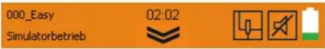
text_image
000_Easy 02:02 SimulatorbetriebThe Info / Status bar contains:
- Model memory with model name
- Position in the menu
- Time of day
- Double-arrow symbol for opening / closing the current menu or the main menu.

- Telemetry output status display:

Sound off

Vario tone output

Announcement of the telemetry data

Alternating telemetry data and vario tone output
The Telemetry status can be changed by pressing this symbol, and by using the Teacher / Vario button. The status is stored for the flight phase currently selected.
- Symbols for special operating modes:

Simulator mode active

Trainer mode active

Pupil mode active

Range check active

Throttle emergency off active
- Battery state display

9. Main menu
You can call up the Main menu by pressing the double arrow symbol in the Status bar.
Main menu:
text_image
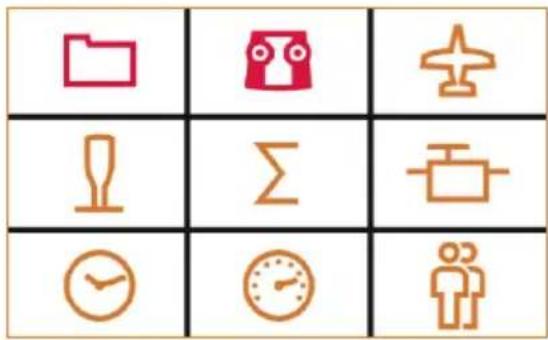
Grid of nine icons representing folder, airplane, trophy, alarm, clock, timer, and person with Chinese labelsThe individual menu points are arranged as follows:
- Memory card symbol: The model memory

Here you can select an existing model saved in one of the 200 memory spaces or configure a new model (see section 7).
- Transmitter symbol: Setting the transmitter

a. Under basic settings, the language (D, GB, F) of the battery alarm and the throttle mode (throttle left or right) can be selected.
b. and failsafe tests.
c. the fo
- Touch calibration
- Setting the time
- Performing updates
-
Resetting to factory settings
-
Plane symbol: Model-specific settings
Here you can change the settings for the model:
- Model type
- tail tyoe
- number of flaps
- flight phase settings
- trim settings
- throttle idle position
- throttle check
-
fast response
-
Stick symbol: Transmitter settings

a. Control settings, such as dual rate, expo
b. Control assignment modes 1 to 4
c. Control calibration
- Sigma symbol: Mixer

Here's where you'll find the various setting options of the mixer (see section 7.9).
- Servo symbol: Servo programming

a. Servo settings
- Neutral position adjustment
- End position adjustment (EPA)
- Servo reverse
b. Servo assignment
Assign the functions to the channels on the receiver.
c. Servo monitor
Hint: Set mechanically first!
Before you change (electronic) settings on the transmitter, make sure the mechanics on the model are set as optimally as possible.
- Affix the output arm at right angles to the pushrods on the servo output. This will avoid mechanical differentiation.
- Set the desired neutral position of the ailerons as well as possible by changing the length of the pushrod.
- Mount the pushrods as far inside as possible and use the maximum servo travel. This reduces the effect of gear backlash and makes optimal use of the servo's power.
- Mount the aileron pushods on the horn as far outside as possible. This reduces the effect of play in the pushrods and transfers the servo's power to the aileron optimally.
9. Main menu
7. Clock symbol: Timer menu

Here you can set up both timers.
a) Timer 1
measures the actual motor run time (provided that the throttle control has previously been selected). The timer only runs when the control value exceeds the set switching threshold.
b)
Timer 2
measures the total flight time; it starts when the switching threshold is exceeded, and can only be stopped by pressing "STOP" a second time.
In the corresponding Timer menu you can define the transmitter control for Start, together with the associated ON position or switching threshold.
If you have defined a flight time / motor run time, the timer counts backwards (down) when started. An alarm sounds when the preset time has elapsed, after which the timer continues to count into negative values.
If you set 00:00 as time, then the timer counts upwards with no alarm.
The output of the current timer value can either be started using your choice of switch, or by swiping within the Timer Status display.
8. Speedometer symbol: Telemetry

Setting the telemetry data
- Sensor address 0..3 or 4..7
Here you can change the sensor names in the menus and select which data you want to have displayed and which data you want to have announced.
· Vario
At this point you can alter the Vario address and volume.
· Warning LED confirmation
This is where you switch off the warning LED for voltage and residual capacity ('fueltank' display) if an alarm has been triggered.
- Speech / Interval
At this point you can adjust the volume of speech output and the time interval between the repeat and the output. It is possible to pre-select the telemetry output status by pressing the Telemetry symbol in the Status display, or alternatively by pressing the Teacher / Vario button.
9. Persons symbol:
Teacher / Pupil / Simulator mode
For more information please refer to the
section entitled "Teacher / Pupil".
10. Screen lock
The COCKPIT SX features a screen lock, which can be activated and disabled in any of the five Status displays by holding a free area of the touch-screen pressed for three seconds.
- An active screen lock is confirmed by disabling of the main menu knob and a descending beep.
- A disabled screen lock is confirmed by activation of the main menu knob and a rising beep.
While the screen lock is active it is still possible to switch Status displays and Telemetry output, but all other operating fields are blocked to prevent accidental operation.

11. Keypad
The Cockpit features two different keypads. In addition to the standard keypad (with letters) there is a pure numeric keypad which is automatically superimposed.
text_image
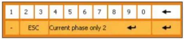
1 2 3 4 5 6 7 8 9 0 ← - ESC Current phase only 2 ← ←Special feature:
If flight phases are active, an additional Enter button is superimposed in the centre of the screen; this can be used to adopt your preferred value for the current flight phase. In contrast, the normal Enter button (right) is used to adopt the value for all flight phases simultaneously.

12. Telemetry
With the COCKPIT SX, you can make use of the advantages of telemetry. A prerequisite for this is the use of a telemetry-capable M-LINK 2.4 GHz receiver and if necessary the corresponding sensors.
The speech output of the telemetry values is integrated into the transmitter. It receives the telemetry data from the model completely independently of the transmitter and announces the values as a speech output along with various sounds and warning signals.
12.1. WINGSTABI
The COCKPIT SX supports (from version 1.20) the output of the WINGSTABI - telemetry.
The following values can be outputted:
- Status messages such as flight mode or flight phase
- Display of sensitivity for aileron - elevator - rudder
- Display of the receiver voltage
First, activate the telemetry transmission for "COCKPIT" in the WINGSTABI using the MULTIPLEX launcher in the transmitter settings. Assign the desired telemetry values to the addresses.
Next, you can select the addresses which are to be displayed or announced in the telemetry menu of the COCKPIT SX.
The announcement of the WINGSTABI status messages always has priority.
13. SAFE-LINK
The COCKPIT SX is equipped with an innovative technology termed MULTIPLEX SAFE-LINK. This allows the user to avoid possible confusion by assigning an individual "code number" to each model memory; this is available with immediate effect.
If you accidentally select a model memory which does not match the SAFE-LINK code stored in the receiver, then the receiver is not activated; the feature works in a similar manner to a car immobiliser.
The SAFE-LINK code is transmitted every time a "binding" procedure is carried out; it is then stored in the receiver.
The software reserves fifty SAFE-LINK numbers for you, any of which you can select at will.
If you do not wish to use the SAFE-LINK function, you can simply leave this option at "OFF".
The SAFE-LINK function represents an important safety enhancement, but the following points must be observed:
- You must never, under any circumstances, activate or disable the SAFE-LINK function, or change the SAFE-LINK number, when the model is switched on!
Exception: see SAFE-LINK switch
Injury hazard! The model's motor could start running if the fail-safe setting is incorrect or undefined.
- Every time you activate or disable SAFE-LINK, or change the SAFE-LINK number, it is essential to carry out a new "binding" procedure. We also strongly recommend that you set "fail-safe" with throttle in the OFF position.
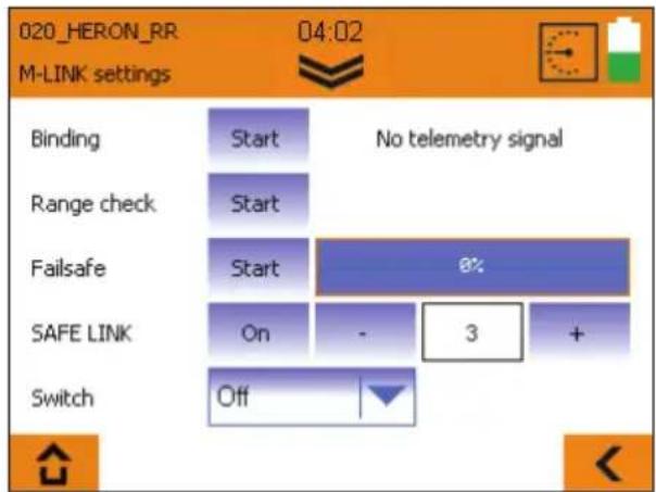
text_image
020_HERON_RR M-LINK settings 04:02 No telemetry signal Binding Start Range check Start Failsafe Start 6% SAFE LINK On - 3 + Switch Off
SAFE-LINK switch;
The SAFE-LINK function can be expanded by assigning a SAFE-LINK switch and defining a SAFE-LINK number.
This makes it possible to switch between several SAFE-LINK numbers during a session.
This function is particularly useful with multi-function (ground-based) models, where the operator needs to switch quickly and conveniently between several vehicles - e.g. dredger -> low-loader / tipper -> bulldozer - using the same radio control transmitter. The model settings must be the same.
To use this feature it is necessary to assign a switch and a SAFE-LINK number. You then move the SAFE-LINK switch to the desired position, and "bind" the appropriate model. Please note that all the models must share the same model settings.
If you wish or need to control models with entirely different settings, we recommend that you do not use the SAFE-LINK switch. Instead you should set up different model memories with individual SAFE-LINK numbers. You can then switch model memories during the session.
We recommend that you only use the SAFE-LINK switch function with multi-function (ground-based) models, where safety is not usually an issue.
14. MULTIGYRO CSX
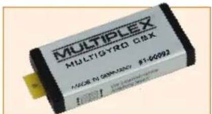
The COCKPIT SX can be fitted with the supplementary MULTIGYRO CSX module.
The COCKPIT SX 12 is fitted with this module as standard. The unit is a gyro / position sensor, which can be used either to control servos directly, or optionally to switch various functions. It is also possible to use it as input in servo mixers and transmitter control mixers.
The "Gyro" set-up menu for the MULTIGYRO CSX can be found in the Main menu under the Trainer symbol.

Pages 1 / 2 display the current values for the position sensors for the axes X, Y, Z and the gyro sensors Ax, Ay, Az.
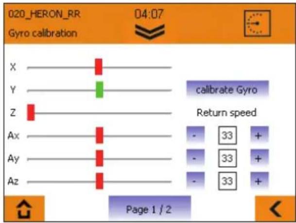
text_image
020_HERON_RR Gyro calibration 04:07 X Y Z calibrate Gyro Return speed Ax Ay Az - 33 + - 33 + - 33 + Page 1 / 2The position sensors X, Y, Z behave in a similar manner to a spirit level: they react to the absolute position of the transmitter in space.
The gyro sensors Ax, Ay, Az react to acceleration and torque (angular travel): the movements around each axis are summed. Each sensor also has a Return value which determines how fast it returns to the Centre position.
Base setting:
- Hold the transmitter in a comfortable attitude, as if you were actively controlling a model.
- Press the "Calibrate gyro" field to set the centre positions to suit your normal attitude. (The Z-axis is set to a non-central position; it will change when you set the transmitter upright).
- The sensor calibration is stored in the active model memory.
Usage:
The output of the Gyro and position sensors can be sent directly to a servo channel, e.g. for controlling a gimbal. Simply assign the appropriate axis in the "Servo assignment" menu.
A further possible use is in conjunction with transmitter control mixers and servo mixers; in this case the sensors can be used as inputs.
The gyro and position sensors can also be used as switches. For example, speech output for a Timer or Telemetry can be started by moving the transmitter itself.
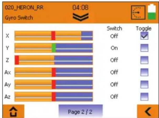
text_image
020_HERON_RR Gyro Switch 04:08 Switch Off Y Z Ax Ay Az Switch Toggle On Off Off Off Off Page 2 / 2On page 2 / 2 you can set the corresponding switching thresholds by adjusting the orange bars, and select the switching characteristics of the gyro switches. The axis position displays feature two colours: they change from red to green to indicate that the set threshold has been exceeded, i.e. the associated switch is now active.
If you select the Toggle function, the switched state is retained once the threshold is exceeded; it is only reset when the threshold is exceeded again.
Example:
Timer 1 is to be spoken when the transmitter is set upright. Set the threshold for "Z" as illustrated above.
Move to Timer 1 in the Timer menu, and assign the switch "Position Z On" under "Start using".
Timer 1 is spoken as soon as you set the transmitter upright.

15. Example - 4-flap glider
Programming a (4-flap) glider is extremely easy:
- Create a new model using the assistant, select the "glider" type. Give your model a name.
- In the next menu, "model type", activate the use of "four flaps".
Important:
The exterior pair of flaps is called the ailerons, the interior two flaps are called flaps (also camber-changing flaps).
- Perform the guided programming up to the "Servo settings".
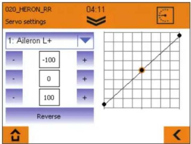
text_image
020_HERON_RR Servo settings 04:11 1: Aileron L+ - -100 + - 0 + - 100 + Reverse- Click the selection box. The list of servos appears; the preselected numbers correspond to the servo position on the receiver, followed by the control function. Connect the servos to the receiver according to the list if you have not done so already.
- Check the direction of rotation of the servos; should it be necessary to change them, you can change the direction after selecting the corresponding servo by pressing the "reverse" field.
Hint: In this step, the flap servos are still controlled via one of the rollers on the back of the transmitter. The flap servos should both run in the same direction when pressing the "flap" operating element!
- Bring the operating element for throttle (joystick/roller) into the throttle off position, and all others into the middle position.
Hint: Before beginning with the servo settings on the transmitter, all control surfaces should be mechanically aligned correctly; a fundamental require-
ment is that the model is constructed carefully. Correct all control surfaces which are distinctly off the middle position by mechanically shifting the servo lever, or by changing the linkage.
- Now begin setting the elevators and rudders (elevator+ and rudder); first optimize the middle position, after which you can set the full deflections recommended by your model's manufacturer.
- When setting the ailerons (Aileron L/R+) and flaps/camber-changing flaps (Flap L/R+), proceed as follows:
Control the ailerons successively upwards, and for each one measure the travel achieved without exceeding the mechanical limits. Note down the smaller of the two values. Set the servo travel on the transmitter so that the smaller value of the two servos you noted down is achieved.
Measure the downward deflection of the two ailerons, and set the smaller of the two values for both control surfaces. Adopt the same procedure for the flaps/camber-changing flaps.
Setting the servo travels specified by the model manufacturer is only performed in the next step in the "Mixer" menu.
- Using the arrow symbol at the bottom right, switch to the next settings menu level "Mixer".
If you have activated the use of flight phases in the assistant, please note that all mixer settings you make in the following steps can and must be set individually for all flight phases. In this case, you need to select all flight phases and transfer the value after changing a value using the flight phase switch "PHASE".
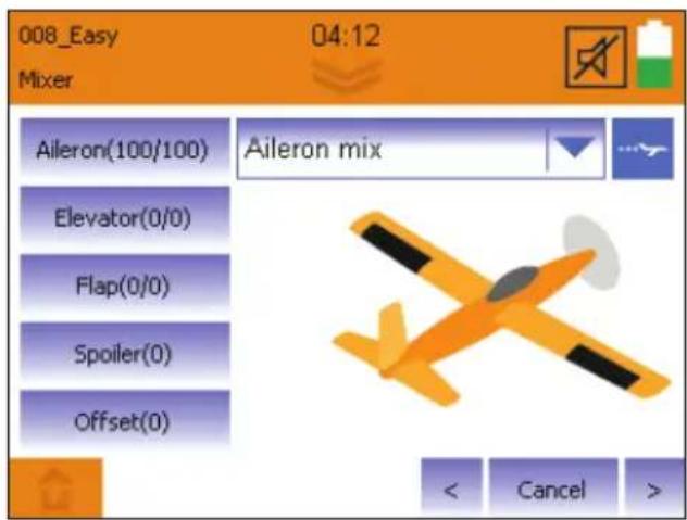
text_image
008_Easy Mixer 04:12 Aileron(100/100) Aileron mix Elevator(0/0) Flap(0/0) Spoiler(0) Offset(0) < Cancel >· In the selection field at the top right, select "Aileron mix"
15. Example - 4-flap glider
Aileron mix:
The mixable inputs can be found on the left:
Aileron:
Here, you can set the full aileron deflections and at the same time the differentiation (different deflections upwards and downwards).
Flaps:
If you want to use the speed and thermal position on your model, you can set the desired full deflection for speed and thermal position of the ailerons here. The setting is performed as follows:
In the middle setting of the flap control (in this step another one of the back rollers), the camber-changing flaps should be in neutral position.
Bring the operating element for the flaps into the desired full deflection position for the full thermal position, check to which of the two values the control surfaces respond, and adjust the deflections according to the specifications.
Bring the operating element for the flaps into the desired full deflection position for the full speed position, use the second value, adjust the deflections according to the specifications.
Hint:
Should you prefer selecting a fixed
warping of the surface for each flight phase (provided you have activated flight phases), you can overwrite the function of the roller next in the control settings by setting "Fix"-values for each flight phase. As you have already performed the travel settings with the mixer in this step, it is sufficient for "Fix" to enter the values (-100, 1 and +100).
Elevator:
Here, the so-called snap-flap function (e.g. for tight turns around the elevator axle) can be set, change the deflection here, which the aileron should take when pulling or pushing the elevator. This function is only active if the "SNAP" switch is in the active position.
Spoilers:
The spoilers are the operating element for approaching the landing position (also referred to as butterfly/crow). This step will work with another of the rollers on the back of the transmitter or the joystick.
To raise the aileron for landing, first enter "100" here. If the ailerons are running in the wrong direction, enter "-100", move the roller (or joystick) into the position in which the ailerons are completely extended. Next, reduce the numerical value until the control surfaces have adopted the desired position.
Feature: The COCKPIT SX M-LINK has an automatic fade out of the aileron differentiation. This means that even when the ailerons are completely extended for landing, the model can still be controlled using the aileron axle.
Should you prefer selecting a fixed landing position in a flight phase, you can overwrite the function of the roller subsequently in the controller settings under spoilers by setting "Fix" values for each flight phase. As you have already made the travel settings via the spoiler mixing, it is sufficient for fix to enter the values +100 for extended or -100 for retracted.
Offset:
This setting is reserved for experts. If you don't need an offset, you can skip this setting:
If, despite a spoiler value of "100", the travel for lifting the aileron required for the landing position is not achieved, the servo center can be shifted "mathematically" in this step.
This is possible because for controlling the aileron with most models, 2/3 of the travel up and only 1/3 of the travel down is required.
First, set the ailerons using the operating element for the spoilers to the extended position. Measure how much additional travel upwards is required, and bring the control surfaces back into the neutral position. Increase the value for offset so far so that the control surface is down by the previously measured value. Next, the aileron linkage must be mechanically set back into the neutral position.
Then, check the full travel of the affected servo, and adjust it if necessary following the programming in the "servo settings" for both servos.
- Now, in the selection field at the top right, select "Flap mix"
15. Example - 4-flap glider
Flap mix
The mixable inputs can be found on the left:
If you do not use any flaps/camber-changing flaps, you can skip this step and continue from "Elevator mix".
Flaps:
If you want to use the speed and thermal position on your model, you can set the desired full deflection for speed and thermal position of the flaps here. The setting is performed as follows:
In the middle position of the flap control (in this step another one of the back rollers), the camber-changing flaps should be in neutral position.
Bring the operating element for the flaps into the desired full deflection position for the full thermal position, check to which of the two values the control surface responds, and adjust the deflections according to your specifications. Bring the operating element for the flaps into the desired full deflection position for the full speed position, use the second value, adjust the deflections according to your specifications.
Aileron:
If the flaps/camber-changing flaps are to travel with the ailerons, you can set the proportional slaving here.
Spoilers:
Here, you can set the position of the camber-changing flaps for landing when actuating the spoiler controller just as described under aileron mix.
Offset:
This setting is reserved for experts. If you don't need an offset, you can skip this setting: Just as for the offset function of the "Aileron mix", the zero point of the camber-changing flaps can be moved here, in case the servo travel does not reach down far enough.
First, set the camber-changing flaps using the operating element for the spoilers to the extended position. Measure how much additional travel downwards is required, and bring the aileron back to the neutral position. Increase the value for offset until the aileron is up by the previously measured value. Next, the aileron linkage must be mechanically set back into the neutral position.
Then, check the full travel of the affected servo, and adjust it if necessary following the programming in the “servo settings” for both servos.
- Now, in the selection field at the top right, select “Elevator mix”
Elevator mix
The mixable inputs can be found on the left:
Elevator:
Here, you can set different deflection sizes for the elevator for various flight phases, if required.
Flaps:
Here, you can mix height or depth if the nose of your model raises or dips a little in speed or thermal position. (flap compensation)
Bring the operating element for the flaps into the speed position, check by testing to which of the two values the elevator responds, and set the desired deflection size.
Bring the operating element for the flaps into the thermal position, use the second value, and set the desired deflection size.
Spoilers:
Here, you can set the so-called spoiler compensation if the nose of your model raises or dips a little in the landing position.
Bring the operating element for spoiler into the extended position, set the required deflection size on the elevator.
Throttle:
Here, you can set the so-called throttle compensation if the nose of your model raises or dips a little when increasing the throttle.
To do so, bring the throttle operating element into the extended position, and set the required deflection size on the elevator.
- Now continue programming with the assistant using the arrow to the right to the "Controller settings".
15. Example - 4-flap glider
Controller settings:
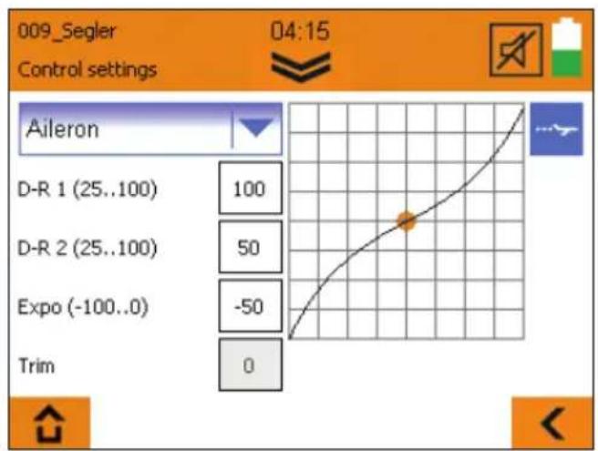
text_image
009_Segler 04:15 Control settings Aileron D-R 1 (25..100) 100 D-R 2 (25..100) 50 Expo (-100..0) -50 Trim 0In the controller settings, you can specify your controlling habits. These settings must be made separately for each flight phase when flight phases are activated.
- Now select one of the operating elements at the top left of the selection field.
The following settings can be made:
D-R1/D-R2
Here, you can assign the various deflection sizes (the so-called dual rate) to the currently selected operating element (aileron/elevator/rudder). The switching is done with the "DUAL RATE" switch.
Example:
The model is easy to control in slow flight, whereas in fast flight its reactions are too strong for you. In such cases with D-R2, enter a smaller value (e.g. 70%). This way, you can reduce the control travel with the D-R2 switch during fast flight.
EXPO
If you find a model too agile, you can use Expo to make the reactions on the joystick slightly more sensitive around the central position.
For beginners, a setting of approx. -20% to -30% is recommended. The Expo value must always be entered with the "-" sign.
FIX
Using the "Fix" value, it is possible to overwrite the two operating elements for spoilers or flaps proportional to the back of the transmitter with a fixed value. The use of this function only makes sense with activated flight phases.
Example: Speed and thermal positions should be selected directly via the flight phases. Switch the flight phase switch to the thermal phase, change the value to a range between -100 and 100, so that the camber-changing flaps are in the desired position.
Switch to the speed phase, and proceed in the same way. If the value "0" is entered, the operating element for spoilers or flaps is active. So enter the value "1" in the switch position for the normal phase.
Slow:
This value is exclusively available for the "throttle" operating element.
By increasing the value, you can achieve a delayed start of the engine. The value is specified in 1/10 seconds. The maximum value of 35 therefore represents a delay of 3.5 seconds.
- Subsequently, the programming can be ended by pressing the "save" button.
- You have programmed your model.
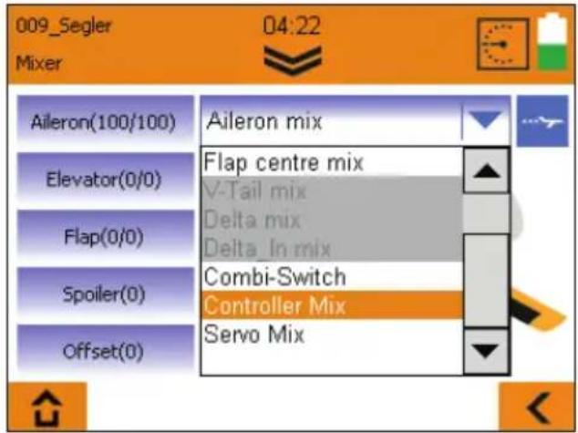
16. Free mixers
The COCKPIT SX M-LINK (from V1.20) has a total of 8 additional free mixers, which can be found in the mixer menu under "Controller mix" and "Servo mix".
text_image
009_Segler Mixer 04:22 Aileron(100/100) Elevator(0/0) Flap(0/0) Spoiler(0) Offset(0) Aileron mix Flap centre mix V-Tail mix Delta mix Delta_In mix Combi-Switch Controller Mix Servo MixThe mixer settings can and must be made separately for each flight phase.
Make absolutely sure that your model motor does not start inadvertently; thoroughly check all mixers and settings before use!
Both mixer types are set up identically. To use, first select mode, input (source), output (target), and if desired a switch for activating the mix. The line behind the switch name indicates the switch setting which activates the mixer.
The mixer has the following possibilities:
- "Off" mode - the currently selected mixer is deactivated.
- "Mix" mode
The input is mixed with the output, using the three-point-curve, the extent of the mixing and the effective direction can be influenced.
- "Overwrite" mode
The original signal at the output is completely replaced with the input signal. Using the three-point-curve, the extent of the mixing and the effective direction can be influenced. If "Overwrite" is set at the same output in several mixers, the mixer with the higher number always has priority.
The function of the "input" constantly remains unchanged, the mixing result is effective on all servos which are connected directly or via mixer to the "output".
Controller mix
Using the 4 controller mixers, operating elements (e.g. aileron, elevator, rudder, ...) can be mixed with each other. The mixing result is effective on all servos which are connected with the controller entered under "output".
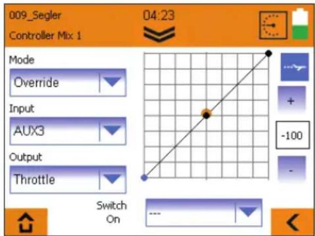
Example: Controller mix - "Overwrite" mode:
If, for instance, the throttle is to be operated using a switch (e.g. AUX3) instead of the joystick, set the controller mixer as follows:
text_image
009_Segler Controller Mix 1 04:23 Mode Override Input AUX3 Output Throttle Switch On -100
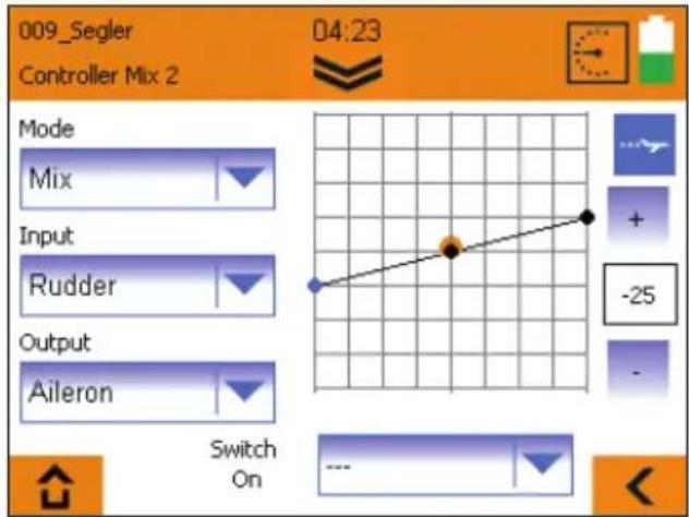
Example: Controller mix - "Mix" mode
If, during knife edge flying, your model swings over the aileron axle, you can create a Knife edge flight mixer:
text_image
009_Segler Controller Mix 2 04:23 Mode Mix Input Rudder Output Aileron Switch On -25Set the mixer as shown in the image, move the rudder joystick to the full deflection positions, adjust the aileron reactions by changing the three-point-curve.
If the model also swings over the elevator, an additional controller mixer can be created. Select input rudder, output elevator, adjust the desired elevator reaction by changing the three-point-curve.
16. Free mixers
Control Mix
- Example: "Overwrite" transmitter control mixer mode: The throttle and landing functions (spoiler) are to be controlled by one stick, according to flight phase:
Function in the Landing flight phase:
Throttle is controlled by the roller, the spoiler function with the stick.
Function in the Launch and Normal flight phases:
Throttle is controlled exclusively using the stick.
Caution!: for safety reasons it is essential to remove the propeller before continuing with the programming procedure.
- Set up a new model using the "Glider" model type, with active flight phases.
- Assign the transmitter controls in such a way that the spoiler function is on the stick, and throttle is on the roller.
- The next step is to program the model completely, with separate Throttle / Spoiler functions, right through to the end.
- Ensure that all the mixers have a Spoiler input in the Landing phase only.
Creating the transmitter control mixer required:
The purpose of the mixing arrangement is to ensure that throttle is controlled by the stick in all flight phases with the exception of the Landing phase.
- Select Transmitter Control Mix 1.
- Select Launch phase using the flight phase switch.
- Set the mode to "Overwrite", select "Spoiler" as input and "Throttle" as output.
- Leave the curve points at -100, 0, +100%; the switch stays at “---”.
- Use the flight phase switch to select Normal phase, and repeat the settings for this flight phase.
- Now switch to the Landing flight phase; the Mode here must be set to "Off".
Caution!
Before you fly the model using this mixing arrangement, it is absolutely essential to remove the propeller and check all the settings extremely carefully. Pay particular attention to the spoiler and throttle functions, the flight phases and the mixers.
Servo mix
Using the 4 servo mixers, operating elements or even mixers can be mixed directly on servos.
All "inputs" whose names end with "+" are mixers (e.g. elevator+); all remaining inputs are operating elements.
The outputs are always servos; they are displayed with position numbers on the receiver and the corresponding function.
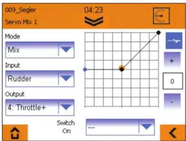
Example: Servo mix - "Mix" mode:
With a dual-motor plane, the motor on the outside of the curve is to be additionally accelerated during curve flight to support the effect of the rudder.
- To do this, assign the "Throttle+" function to a second channel (e.g. 7 Throttle+) in the servo menu under "servo assignment". Check that both regulators are working properly.
- Create a servo mixer for the left motor, set the three-point-curve so that the throttle is increased slightly when controlling the rudder to the right, as shown in the following image.
text_image
009_Segler Servo Mix 1 04:23 Mode Mix Input Rudder Output 4: Throttle+ Switch On- Create an additional servo mixer (see image) for the right motor, and enter the number of the second servo channel under "output".
- Adjust the three-point-curve. (It should run symmetrically to the curve of the first mixer).
17. Teacher/pupil/simulator mode
With the COCKPIT SX M-LINK, you can operate wireless teacher/pupil and simulator mode.
Using the button, call up the teacher/pupil/simulator menu.
Teacher mode
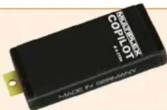
For teacher mode, the optionally available "Copilot" component must be used (ord.No. # 45184). It can be fitted into any socket labeled with "Module" in the transmitter interior. Using the Torx key included, remove the 6 casing screws which sit in holes of approx. 7mm diameter. Carefully lift up the back wall; the connecting wire to the back wall of the transmitter should not be subjected to any tensile strain. Insert the Copilot component and secure it with the screw included. Carefully replace the back wall, paying close attention to the connecting wire; it should not be anywhere near the moving parts of the joysticks. Screw the back wall of the transmitter back on again.
- Select "Teacher" and activate the teacher mode in the following menu.
- Switch on the pupil.
If teacher and pupil have not yet been connected to each other, the following steps must be carried out:
- Start the pupil search on your transmitter.
- Start pupil mode on the pupil transmitter ("Binding" on older devices)
As soon as the pupil has been recognized, the notification "Pupil connected" appears.
- Select which control functions are to be transferred to the pupil.
- You can start and stop the transfer by pressing the "TEACHER/VARIO" button.
A special feature is the "automatic transfer function" - if the teacher must quickly intervene, the teacher can gain complete control of the model immediately simply by moving the joysticks.
Pupil mode
The Cockpit can be used as a pupil transmitter with every MULTIPLEX teacher transmitter which is equipped with a Copilot or teacher-pupil-stick.
- Select "Pupil".
- If teacher and pupil transmitters are not yet connected, the notification "No telemetry signal" appears.
- Bring the Copilot/teacher-pupil-stick into pupil search mode ("Binding") on the teacher transmitter.
- Press "Start"
- After the teacher has been found, pupil mode can be started.
Simulator mode
Wireless simulator mode is possible using the optionally available MULTIflight stick (ord.No. # 85147). To start simulator mode, proceed as follows:
- Select "Simulator mode".
- If COCKPIT and MULTIflight stick are not yet connected, the notification "No telemetry signal" appears.
- Bring the MULTIflight stick into the transmitter search mode ("Binding")
- Press "Start"
- Once the MULTiflight stick has been recognized, simulator mode can be started.
18. Update
The COCKPIT SX M-LINK software can be updated as follows using the included MINI-USB cable and the free software MULTIPLEX launcher.

MULTIPLEX launcher can be downloaded free of charge at www.multiplex-rc.de in the software download section.
Performing the update:
- Ensure that your transmitter is fully charged.
- Install the MULTIPLEX launcher.
- Switch on your transmitter.
- Insert the USB cable into your PC and transmitter. The selection menu "USB mode" appears.
- Select "USB data connection".
- Start the MULTIPLEX launcher.
- Select "Cockpit SX Manager" on the launcher.
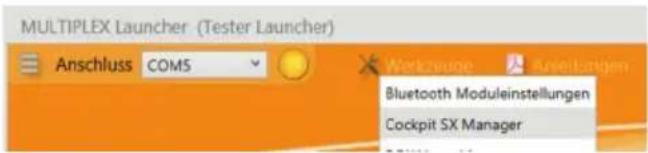
text_image
MULTIPLEX Launcher (Tester Launcher) Anschluss COM5 Bluetooth Moduleinstellungen Cockpit SX Manager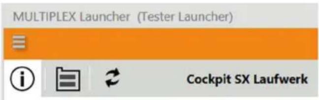
text_image
MULTIPLEX Launcher (Tester Launcher) Cockpit SX Laufwerk- Press the update symbol.
- Select the appropriate firmware and press "Install".
- Follow the further instructions of the MULTIPLEX launcher.
- Carefully check all your model and transmitter settings after the update.

19. Care and maintenance
The transmitter does not need any special care or maintenance. We strongly recommend an inspection of the sender dependent on its use by an authorized MULTIPLEX service center every two to three years. Regular functionality and range tests are obligatory.
A soft bristle brush is recommended for removing dust and dirt. Stubborn stains, particularly fats and oils, can be removed using a damp cloth and if necessary a mild household cleaner. Under no circumstances should you use "heavy-duty" cleaning agents such as spirits or solvents!
Avoid jolting or applying undue pressure to the transmitter. The transmitter should be stored and transported in a suitable container, such as a case or transmitter bag. See section 17 recommended accessories!
We update and improve our products on a regular basis. You can find software updates for Multiplex products on the Internet at www.multiplex-rc.de under Software. It's worth paying a visit regularly!
- Recommended accessories
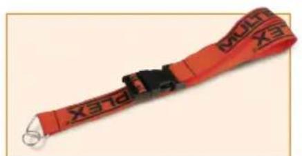
natural_image
Red and black striped shipping strap with 'X316' branding (no additional text or symbols)8 5715 Transmitter carrying belt
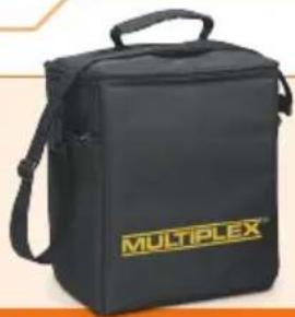
natural_image
Black multiflex branded bag with yellow logo, no visible text or symbols on the bag itself76 3322 Transmitter bag

text_image
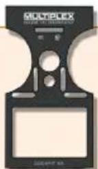
MULTIPLEX M-LINK(....)76 3323 Transmitter case

natural_image
Close-up of a black audio jack with earbuds and cord, no visible text or symbols8 5071 Earphones
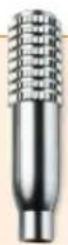
7 5308 Stick grips Alu long
text_image
COPILOT Made in Germany4 5184 COPILOT
natural_image
Two identical multiplexer handbags, one yellow and one black, displayed side by side (no text or symbols visible)72 4404 sticker yellow SX 7 / 9# 72 4403 sticker carbon SX 7 / 9

natural_image
Green-tinted trophy with a blank plaque, no visible text or symbols72 4408 sticker green SX 7 / 9
natural_image
Red electronic device with black wires, no visible text or symbols on body55012 WINGSTABI-RX-7-DR M-LINK
55013 WINGSTABI-RX-9-DR M-LINK
text_image
MULTIPLEX MULTIGYRO CSX 11008-01-G996-2007 #1-600931-00092 MULTIGYRO CSX
text_image
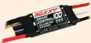
ROXXY SMART CONTROL 100 VELOCITY VS55 SYSTEM 11.16.128.337V/100A CE: 10V/10V/10VROXXY SMART Control MSB 45 / 70 / 100
text_image
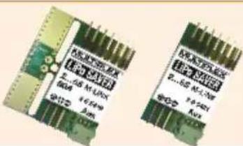
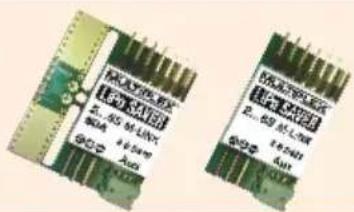
Two printed electronic components with visible model numbers and Chinese branding text.85419 LiPo SAVER 2...6S - 60A
85421 LiPo SAVER 2...6S
21. Advice and technical support
We have made a great effort when writing these short instructions to ensure that you can quickly and easily find the answer to every question.
If, however, you still have an unanswered question about your COCKPIT SX, please contact your retailer, who will be happy to assist you.
You can find the addresses of our service partners on our website: www.multiplex-rc.de under CONTACT/SERVICE.
MULTIPLEX Modellsport GmbH & Co.KG
text_image
MULTIPLEX MADE IN GERMANY COCKPIT SXtext_image
a f e Multiplex® COCKPIT BX c b d CE 0682text_image
Grid of nine icons including folder, airplane, trophy, and clock, arranged in two rows with different line styles.bar
| Category | Start | End | | -------- | ----- | --- | | X | 0 | 1 | | Y | 0 | 1 | | Z | 0 | 1 | | Ax | 0 | 1 | | Ay | 0 | 1 | | Az | 0 | 1 |
natural_image
Red and black striped shipping strap with 'XTEX' branding (no additional text or symbols)natural_image
Black multiflex branded bag with handle and logo (no visible text or symbols beyond branding)natural_image
Close-up of a black audio jack with a strap and connector (no visible text or symbols)8 5071 Ecouteur
7 5308 Manches Alu long
text_image
COPILOT Made in Germanynatural_image
Green-tinted trophy with a blank plaque, no visible text or symbolsnatural_image
Red electronic device with black wires, no visible text or symbols55012 WINGSTAB I-RX-7-DR M-LINK
55013 WINGSTABI-RX-9-DR M-LINK
text_image
MULTIPLEX MULTIGYRO CSX MASC-01 38MM/50Hz P1-005021-00092 MULTIGYRO CSX
text_image
ROXXY SMART CONTROL 100 VELOCITY STOCK: 10.72-33.39V/16W CE : 50V / 100V / 100V / 100VROXXY SMART Control MSB
45/70/100
text_image
LED L-1.58 M-LINK R24 6x100% LED85419 LiPo SAVER 2...6S - 60A
85421 LiPo SAVER 2...6S