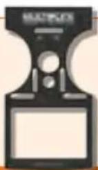
Cockpit SX 9 Set - Remote control toy MULTIPLEX - Free user manual and instructions
Find the device manual for free Cockpit SX 9 Set MULTIPLEX in PDF.

| Product type | Radio control transmitter for model aircraft (planes, helicopters, multicopters) |
| Brand | Multiplex |
| Model | Cockpit SX 9 Set |
| Number of channels | 9 |
| Frequency | 2.4 GHz (2400-2483.5 MHz) |
| Link technology | M-LINK |
| Power supply | LiFePO battery 3.3 V / 4000 mAh, rechargeable via USB port (mini-USB) |
| Weight | Approx. 850 g |
| Dimensions | Approx. 190 x 210 x 60 mm |
| Model memory | 200 slots |
| Display | Color touchscreen |
| Antenna | Integrated IOAT antenna |
| Operating temperature range | -15 °C to +55 °C |
| Safety functions | Throttle check, fail-safe, emergency stop (T-Cut), range test |
| Telemetry | Yes, with M-LINK compatible sensors, voice communication |
| Supported model types | Easy, Acro, Glider, Delta wing, Helicopter, Multicopter |
| Flight phases | Up to 4 phases depending on model type |
| Programmable mixes | Yes, multiple mixes (ailerons, elevator, throttle, etc.) |
| Maintenance | Cleaning with soft brush and damp cloth; overhaul every 2-3 years by authorized service center |
| Recommended accessories | USB cable included; optional USB chargers (MULTIPLEX #14 5533, #14 5534) |
Frequently Asked Questions - Cockpit SX 9 Set MULTIPLEX
User questions about Cockpit SX 9 Set MULTIPLEX
0 question about this device. Answer the ones you know or ask your own.
Ask a new question about this device
Download the instructions for your Remote control toy in PDF format for free! Find your manual Cockpit SX 9 Set - MULTIPLEX and take your electronic device back in hand. On this page are published all the documents necessary for the use of your device. Cockpit SX 9 Set by MULTIPLEX.
USER MANUAL Cockpit SX 9 Set MULTIPLEX
text_image
Grid of icons including folder, camera, airplane, trophy, minus sign, clock, clock with corresponding symbolsnatural_image
Red and black striped object with a looped strap, no visible text or symbolsnatural_image
Black rectangular backpack with gold logo, no visible text or symbols on bodytext_image
MULTIPLEX M-LINK( )76 3323 Senderkoffer
natural_image
Close-up of a black plastic electronic device with a coiled cable (no visible text or symbols)8 5071 Ohrhöhrer
7 5308 Knüppelgriffe Alu lang
text_image
COMPRESS COPILOT- Introduction ...... 13
1.1. Guarantee and limitation of liability 13
1.2. CE declaration of conformity 13
1.3. Disposal 14
1.4. Safety information ...... 14
1.5. Other instructions and checks .... 15 - Specification 15
- Power supply and charging 16
-
Operating elements ...... 16
-
The transmitter from below 17
- Switching on for the first time 18
- Creating a model 18
- Touch display/main menu 21
- Telemetry 22
- Advice and technical support 22
- Care and maintenance 23
- Recommended accessories 23
1. Introduction
Congratulations on purchasing your new RC set, we are delighted you have chosen the MULTIPLEX COCKPIT SK M-LINK. You are holding the ideal equipment for getting into the hobby of flying remote controlled models. We hope you enjoy it and wish you the best of luck with your new equipment.
1.1. Guarantee and limitation of liability
MULTIPLEX Modellsport GmbH & Co.KG does not assume any liability for loss, damage or costs which arise through the improper use and operation of our products, or which are connected with such operation in any way. As far as is legally permissible, the obligation of MULTIPLEX Modellsport GmbH & Co.KG to provide compensation for damages, on whatever legal basis, is limited to the invoice amount of the quantity of MULTIPLEX Modellsport GmbH & Co.KG goods that were directly affected by whatever incident gave rise to the damage. This does not apply if MULTIPLEX Modellsport GmbH & Co.KG is obliged to accept unlimited liability in accordance with mandatory law for deliberate or gross negligence.
Our products are covered by the currently valid statutory guarantee regulations. If you wish to make a claim under guarantee, please contact the model shop where you purchased the product.
The guarantee does not cover malfunctions caused by the following:
- Improper Operation
- Maintenance that was performed incorrectly, late or not at all, or performed by a non-authorized body
- Incorrect connections
- Use of non-original MULTIPLEX accessories
- Modifications/repairs that were not carried out by MULTIPLEX or a MULTIPLEX Service Centre
- Accidental or deliberate damage
· Faults due to normal wear and tear - Operation outside the technical specifications or in connection with components from other manufacturers.
MULTIPLEX Modellsport GmbH & Co.KG
Multiplex/HiTEC Service:
+49 (0) 7252 - 5 80 93 33
1.2. CE declaration of conformity
The device was evaluated according to directives harmonized with European legislation. You are therefore in po session of a product whose construction satisfies the protection objectives of the European Community for the safe operation of devices. You can find the exhaustive CE declaration of conformity as a PDF document online at www.multiplex-rc.de in the DOWNLOADS section under PRODUKT-INFOS.
1.3. Disposal
Electrical and electronic equipment which has the crossed out wheelie bin symbol should not be disposed along with household waste, but rather via a suitable disposal system. In countries belonging to the EU (European Union), electrical or electronic equipment may not be disposed of along with general household waste (WEEE - Waste of Electrical and Electronic Equipment, Directive 2002/96/EC).
You can dispose of your old equipment at public municipal collection points (e.g. recycling facilities) free of charge. The equipment will be properly disposed of free of charge here. By returning your old equipment, you are making a valuable contribution towards environmental protection!
1.4. Safety information
- Remote controlled models and equipment are not toys in the conventional sense. Setup, installation of the RC equipment and operation require technical understanding, care and safety-conscious responsible behavior. Errors or negligence could have significant damage as a consequence. As the manufacturer or salesperson has no influence or control over proper setup and operation of the model, we are expressly referring to these dangers and excluding any liability.
- In order to operate your model safely, please adhere to the following safety instructions without fail; you are responsible for the safe deployment of your product:
- Please read these instructions carefully! Please do not use the equipment before you have carefully read these operating instructions and the following safety instructions.
- Under no circumstances must you make any technicalmodifications to the RC equipment. Only use original accessories and replacement parts, receivers and servos.
- If you are using this equipment in combination with products from other manufacturers, please ensure that the quality and functionality of these products has been verified. Every new or modified setup must undergo a careful functionality and range test. Do not launch the equipment or model if something doesn't seem right. First look for malfunctions and eliminate them.
- A model which has for whatever reason gotten out of control can cause significant damage or injury. Liability insurance is therefore a requirement in order to operate any model. Please be sure to bear this in mind, and be aware of the relevant regulations.
· Always observe the sequence for switching on and off, in order to ensure that there is no uncontrolled and dangerous start-up of the motor:
- When switching on: Always switch on the transmitter first, then plug in the flight battery or switch on the receiving system.
- When switching off: Always disconnect the flight battery or switch off the receiving system before switching off the transmitter.
- Have receivers and particularly RC transmitters checked at regular intervals (every two to three years) by an authorized MULTIPLEX service center.
- Only operate the transmitter within the permitted temperature range between -15 and 55 °C. Please note that sudden changes in temperature from cold to warm can cause condensation water to be deposited on the transmitter. Moisture impairs the functionality of the transmitter and other electronic equipment as well.
- In case of moisture in electronic equipment, halt operation immediately, disconnect the power supply and leave the equipment to dry in as open a position as possible (for up to several days). Then carefully perform a functionality test. In severe cases, have your equipment tested by an authorized MULTIPLEX service center.
- Perform a range test and set the failsafe (see section 7.7).
1.5. Other instructions and checks
- Build your model carefully, this applies above all to any necessary repairs to your model. You are responsible for your own actions.
- Attach the servos and aileron pushrods in such a way so that the ailerons move smoothly and do not jam when fully deflected.
- Adjust the output arms and pushrods accordingly. Keep the play as small as possible. This is the only way to ensure that there is no undue strain placed on the servo and therefore to make sure that its performance is fully utilized. These measures ensure the servo has a maximized lifespan and guarantee the highest degree of safety.
- Protect the receiver, batteries, servos and other RC components effectively from vibrations. Follow the instructions given in these operating instructions. This especially involves correctly balancing propellers and rotors. Replace damaged parts or parts which are not running true in the motor.
- Do not stretch or kink the cable and protect it from rotating parts.
- Avoid using unnecessarily long or superfluous servo extension leads and ensure a sufficient cable cross section (voltage loss). A benchmark of at least 0.24 ~mm^2 is recommended. For digital servos in the 79xx, 8xxx or 9xxx model ranges, we would even recommend 0.33 ~mm^2 .
-
Avoid interference pulses caused by static charges and strong electric or electromagnetic fields by taking appropriate interference suppression measures (e.g. by suppressing the electric motor with a suitable capacitor) and ensure sufficient distance is maintained between the RC equipment, receiver aerial, wiring and batteries.
-
Ensure sufficient distance is maintained between wires carrying high currents (e.g. electric motor) and the RC equipment. The wiring between the brushless e-motors and their actuators in particular must be kept as short as possible (benchmark max. 10 to 15 cm).
- Carefully check all functions and familiarize yourself with the operation of the transmitter before launching the model.
- Check ease of motion and absence of play of the ailerons and rotor linkages.
- Ensure stability and flawless condition of pushrods, rotor linkages, hinges etc.
- Check model for breakages, flaws and shear edges on any of the RC components or on the motor.
- Ensure flawless condition and contact safety of wires and plug connections.
- Check the condition of the power supply and its wiring including switch harnesses by inspecting the exterior of the cells. This also involves employing a charging procedure which is appropriate for the battery type with a suitable charger and regularly carrying out maintenance on the battery.
2. Specification
| Channel number 7 - Cockpit SX 79 - Cockpit SX 9 |
| Model memory 200 |
| Transmission mode -15...+55 °C |
| Übertragungsart M-LINK |
| Aerial IOAT |
| Frequency 2400...2483,5 MHz |
| Power supply LiFe battery 3,3V/4000 mAh |
| Total weight approx. 850 g |
| Dimensions approx. 190 x 210 x 60 mm |

3. Power supply and charging
The COCKPIT SX is supplied with power from a robust, long-lasting LiFePO battery. The battery is installed together with the battery management system electronics. When new, the over 4000 mAh supplied by the battery are sufficient to provide a remarkable service life. Additional components increase the power consumption and decrease the service life. Temperatures of under -10°C significantly decrease the service life.
The transmitter battery is responsible for supplying power to this equipment and therefore significantly contributes to operating safety.
GB
Charging the battery via the USB socket
The COCKPIT SX has a mini USB socket for charging on the back, underneath the speech output. You can charge the COCKPIT SX, as follows:
- Using the USB cable plugged into your laptop or PC
- Using the USB 12V DC plug-in charger for power-driven vehicles from MULTIPLEX (# 14 5533)
- Using the USB charger plug 100-240V AC from MULTIPLEX (# 14 5534)
Charging via PC
Switch your PC on. Insert the USB cable supplied with delivery into a USB socket on the PC and into the mini USB socket on the COCKPIT SX and switch the transmitter on. Select "Switch off and charge" and confirm the charging process with "o.k.".
Charging with USB plug-in charger
Insert the USB cable supplied with delivery into the plug-in charger and the mini-USB socket on the COCKPIT SX. Select "Switch off and charge" and confirm the charging process with "o.k.".
The internal charging electronics stop the charging procedure as soon as the battery is fully charged. This prevents the battery from being overcharged.
The safety shutdown ends the charging procedure automatically after four hours. When charging via USB with the PC (charging current approx. 500 mAh), charging occurs up to a maximum level of 2000 mAh. A quick-charge with 1500 mAh is possible using the MULTIPLEX USB plug-in charger.
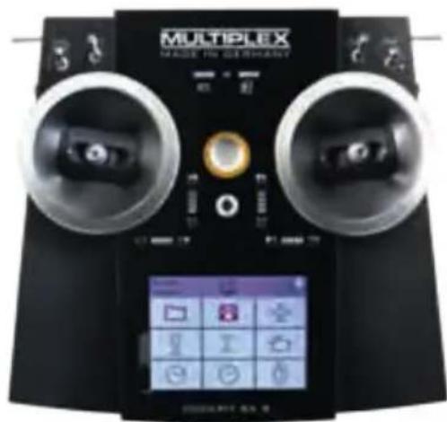
4. Operating elements
The following operating elements can be found on the front:
a. On/off switch
Activate transmitter by briefly pressing the on/off switch.
- flashes orange (transmitter is working and you are in the main menu)
- flashes red (battery empty)
- lights up red (transmitter is not receiving, USB mode) When switching off the receiver, press and hold the switch until the Corona is off. Only then will the transmitter shut down.
b. The two ergonomically arranged joysticks with the corresponding trim buttons
c. D/R switch for Dual Rate 1/2
d. Aux 3 - free 3-position switches (COCKPIT SX9 only)
e. Aux 4 - free 3-position switches (COCKPIT SX9 only)
f. 2-position switches for Snap Flap
text_image
MULTIPLEX MADE TO GEBEVAINTg. LED with gas pump symbol for warning via telemetry when the residual battery capacity gets below a certain threshold (as defined in the power sensor)
h. LED with battery symbol for the telemetry - receiver voltage
4. Operating elements
The following operating elements can be found on the left hand side:
a. 2-position switch CS/A-Red
(switch for Combi-Switch/Autorotation)
b. Teacher-Vario button for trainer mode and status enquiry
The following operating elements can be found on the right hand side:
a. 3-positions switch Phase/Aux 2
(for flight phases or as a free 3-positions switch
b. T-Cut (EMERGENCY-throttle-CUT button)
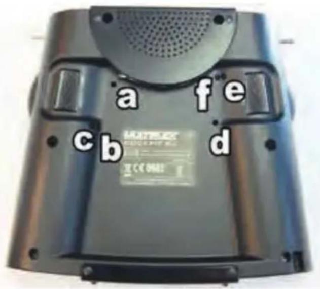
5. The transmitter from below
The housing of the COCKPIT SX is screwed together and does not have to be opened to adjust the spring tension of the stick or to define the throttle stick.
Adjusting screws for the right stick
a. Deactivate tension spring on the stick (stick centring)
b. Adjust stick ratchet
c. Adjust stick sensitivity
Adjusting screws for the left stick
d. Deactivate tension springs on the stick (stick centring)
e. Adjust stick sensitivity
f. Adjust stick ratchet
The appropriate adjusting tool can be found in the left compartment underneath the voice output.
The following operating elements can be found on the back:
a. Rotary knobs for spoilers or throttle limiter (T-LIMIT)
b. Rotary knobs for FLAP/Aux 1
The screws can be reached through openings in the base of the transmitter. The following diagram shows the positions of the various adjusting screws.
text_image
a fe cb dImportant: loosen/tighten screws carefully!
Turn the stick adjusting screws carefully and don't unscrew them too far, if you want to reverse your adjustments for stick centring, ratchet or stiffness again. Otherwise, the screws could press against the base of the transmitter on the inside.
Deactivate the stick centring spring as follows:
Turn screw a (right stick) or e (left stick) clockwise until the stick no longer springs back even at its most extreme position.
Adjusting the ratchet:
Turn screw b (right stick) or f (left stick) clockwise until the strength of the ratchet corresponds with your perceptions.
Adjusting the stiffness:
Turn screw c (right stick) or e (left stick) clockwise until the stiffness corresponds with your perceptions.
The touchscreen pen for operating the display can be found in the slot at the bottom on the right, as shown in the diagram under section 6.

6. Switching on for the first time
To switch on:
Activate the transmitter by briefly pressing the on/off button. If the transmitter has not yet been used, it automatically starts in the basic settings menu.
First of all, you can enter your name and desired language. You can also specify which joystick will be used for the throttle/spoilers later on.
After confirming by pressing the arrow button at the bottom on the right, you are directed to the model assistant, as no models have yet been saved on the SD card. A new model will now be created with the help of the assistant.
GB
7. Creating a model
The easiest way to create a new model is by using the "Assistant".
1. Start the assistant
Under model type, select the one which is best suited to your model. Specify a name and file path for your new model and confirm using the arrow key on the keyboard in the display.
2. Model types
The model types are broken down as follows:
a. Easy
Template for a simple glow-powered model aircraft (e.g. Easystar) without flight phases.
- Aileron with mixable inputs for landing flaps (spoilers), flaps (warping), elevator (snap flap)
- Combi switch (linkage aileron -> elevator/elevator -> aileron)
- Elevator/alternatively
V-tail with mixable inputs to avoid unwanted side effects/compensation of flaps (warping), spoilers (landing damper function) and throttle.
- Channels 1-5 have already been permanently assigned in order to ensure simple programmability.
b. Acro
The Acro template is the template for the classic aerobatic planes and trainers (fun-cub, Funman, Extra....) In addition to the functions listed under Easy, it is also possible to use three flight phases. The servos can be freely assigned. On the mixers (aileron and elevator), the flap mixer input has been consciously deactivated.
C. Segler
The glider template also provides all the necessary functions for gliders as well as those provided by the Easy and Acro:
- Three flight phases
- Two- or four-flap wing
(= two ailerons + two flaps/camber-changing flaps) with mixable inputs for landing flaps (spoilers) e.g. the butterfly
function, flaps (warping), elevator (snap flap), offset for offset linkage of the elevator and V-tail.
• The servos can be freely assigned.
d. Delta
- Three flight phases
- Delta mixer for classic jets/deltas/flying wings
- Unrestricted servo assignment
e. Helikopter
- Four flight phases
· 90 degree flybarless (unmixed)
· 120 degree mixed - Trims which can be switched off for gyros
- Nine point throttle/nine point pitch curve
- Unrestricted servo assignment
f. Multicopter
- Four flight phases
- Four multicopter main window functions
- Nine point throttle/nine point pitch curve
- Unrestricted servo assignment from the remaining transmitter controls/switches
3. Delta / V-tail models
We have come up with something special to save you a lot of time and effort adjusting settings.
Setting the direction of rotation of the servos on delta and V-tail models is child's play. To do this, all you have to do is test through all eight possible combinations for type/variant, until the elevator and aileron function is working as desired.
7. Creating a model
- Use the arrow to go to the next menu "Model type" and select the tail type.
- Use the arrow > to go to the next menu "Model settings" and program the relevant settings in here as well.
Please note: Throttle trim
To trim the throttle, always use the trim button next to the THROTTLE/SPOILER stick, even if the throttle is controlled by another transmitter control.
Please note: Set throttle check
What is a throttle check?
A throttle check is a safety prompt from the throttle operating element. This function prevents motors from starting up on their own and endangering or even injuring you or others. The level of safety when operating the model is increased.
How does the throttle check work?
If the throttle check function is activated, the transmitter checks if the throttle control is in neutral every time it is switched on and when the model memory is switched. If this is not the case, an acoustic warning signal is emitted. The throttle channel is only released after the throttle stick has been moved into the neutral position. When creating a new model, the throttle check is always activated.
6. Use the arrow to go to the next menu
Define the “control assignment” and the desired stick and switch assignment.
- Use the arrow ▶ to go to the next menu "M-Link settings", where you can perform the following actions:
- Binding
The binding procedure binds the receiver to the transmitter. After pressing the "Start" button, binding is active. The Corona on the transmitter flashes rapidly. Now switch on the receiver with the set button pressed (insert the power supply). The LED on the receiver flashes rapidly. The binding should be complete after a few seconds, and then the transmitter and receiver flash slowly again. The servos connected to the receiver can now be controlled.
- Range test
In the M-LINK settings menu (see section 7), the range test will be carried out regularly. After pressing the "Start" button, the range test is active. The transmitter performance is heavily reduced during this procedure. The range test can therefore be carried out without a big distance between the transmitter and the model. By pressing the "Stop" button, the range test is halted. You should be able to control the model at a distance of between 60 and 100 meters (de-
pending on receiver type). Please refer to the receiver instructions for the precise distance.
- Program failsafe
Failsafe is the servo positioning which should be used whenever there is a loss of reception. The current servo positions are saved in the receiver. To save, proceed as follows:
- Move the servos (aileron) on your model to the desired positions using the corresponding COCKPIT SX controls.
- After pressing the "Start" button, the current positions are saved. This can also be viewed on the display. The "Start" button is then visible again.
- Check the failsafe function by switching off the transmitter.
Please note: Cancel or back
If you select the wrong model by mistake or have made a mistake when entering the settings, you can cancel the programming at any time or, using the left arrow key, go back to the previous menu and correct your entries.
8. Use the arrow to go to the next menu "Servo settings".
- Select the relevant servo in the top field In the next three fields, you can set the servo values. In the top and bottom fields, you can set the respective end positions, and the neutral position in the middle field.
There are three options here:
- The - and + buttons
- Tap on the middle of the value to open the character and number field. The current value can be deleted and a new one entered.
· using the graphic display:
a) the neutral position can be adjusted by sliding the middle point
b) by sliding the two outside points, the end position can be set accordingly
Please note: Throttle servo/regulator is not functioning "properly"
If you have chosen a neutral position, but your model's motor gives maximum power in this position, you need to reverse the polarity on the throttle servo (the neutral position must stay where it is, so that THR-CUT (= throttle cut) and throttle check run correctly and the throttle is mixed properly in the elevator!
7. Creating a model
9. Use the arrow to go to the next menu "Mixer". What is a mixer?
When we say mixer, we mean when not just the basic function (e.g. elevation) but also additional controls (e.g. throttle) can control the servo. Example: Your model gains altitude on its own accord when the throttle is increased. This can be compensated by mixing the throttle in the elevator. The elevator is therefore controlled by the THROTTLE and the ELEVATOR.
GB
- Mixing in the elevator
Undesired climb/descent when operating throttle, spoilers or flaps can be compensated for. Elevation is the main input and is controlled by the ELEVATION stick. The other three inputs are mixed and controlled by the THROTTLE, SPOILERS and FLAPS. The result of the mix goes to the elevator.
- Select flaps, spoilers or throttle
- Set the desired values using the - and + buttons or
- Tap on the middle of the value to open the character and number field. The current value can be deleted and a new one entered.
- Mixing the aileron
The aileron mix is done in the same way. Here, there are five options:
- Aileron (aileron mix - for aileron differential)
- Elevator (aileron mix - snap flap) mixing the aileron with harder settings acting as a braking function
- Flaps (aileron mix - flaperon) use aileron as "flaps", with the possibility of extending them upwards
- Spoilers (aileron mix - half butterfly) mixing the ailerons with the flaps
- Offset (aileron offset) the current mixer values are shown in the display.
10. Use the arrow ▶ to go to the next menu "Control settings".
- Select the relevant servo/function in the top field In the next three fields, you can set the dual rate and exponential values.
- Tap on the middle of the value to open the character and number field. The current value can be deleted and a new one entered.
The current setting is shown on the graphic display.
Finally, press "Save", and the menu switches to the timer menu and you have successfully programmed your first model.
Note on using the flight phases:
If you use or activate flight phases on the Cockpit SX7 or SX9, you need to set the mixers for each flight phase separately, or enter the inputs made during one flight into the other flight phases as well (switch between flight phases with the switch at the side).
Example: If you have programmed aileron in the flaps upon starting or during normal flight, you need to then also enter these values for the landing flight phases as well.
8. Touch display/main menu
To switch on: Activate the transmitter by briefly pressing the on/off button.
This opens the timer display. (If you have activated the throttle check, you will receive a corresponding warning signal and will then be sent directly to the main menu).
The timer menu displays
T1 - the motor run time
T2 - the operating time
To reach the telemetry display and the transmitter data, "swipe" left or right with your finger.
Use the double arrow to close the menu.
The orange bar which is now displayed at the top looks like this:

- Model memory with model name
- Position in the menu
• Time - The double arrow opens the timer menu
- Status enquiry symbols:

Sound off
Vario enquiry Announcement of the telemetry data

Announcement of the telemetry data and vario enquiry
The status can also be changed using the button on the left side (teacher/variable).
- Battery status display
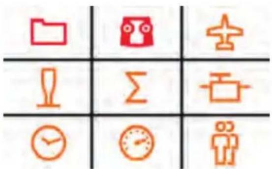
Nine symbols appear in the display at the bottom:
text_image
Grid of icons representing data, time, and personal information symbols in Chinese- Memory card symbol: The model memory

Here you can select an existing model saved in one of the 200 memory spaces or configure a new model (see section 7).
- Transmitter symbol: Setting the transmitter

a. Under basic settings, the language (D,GB,F) of the battery alarm and the throttle mode (throttle left or right) can be selected
b. M-Link settings pertains to the binding, range and failsafe tests
c. the following is possible under System settings:
- Touch calibration
- Setting the time
- Performing updates
-
Resetting to factory settings
-
Plane symbol: Model-specific settings
Here you can change the settings for the model:
- Model type (Easy, Acro, glider, Delta, tail type,
number of flaps)
- You can change special model settings (such as flight phases, throttle, throttle check, M-Link)
- Stick symbol: Transmitter settings

a. Control settings, such as dual rate, expo
b. Control assignment modes 1 to 4
c. Control calibration
- Sigma symbol: Mixer

Here's where you'll find the various setting options of the mixer (see section 7.9).
- Servo symbol: Servo programming

Hint: Set mechanically first
Before you change (electronic) settings on the transmitter, make sure the mechanics on the model are set as optimally as possible.
- Affix the output arm at right angles to the pushrods on the servo output. This will avoid mechanical differentiation.
- Set the desired neutral position of the ailerons as well as possible by changing the length of the pushrod.
- Mount the pushrods as far inside as possible and use the maximum servo travel. This reduces the effect of gear backlash and makes optimal use of the servo's power
- Mount the aileron pushods on the horn as far outside as possible. This reduces the effect of play in the pushrods and transfers the servo's power to the aileron optimally.

8. Touch display/main menu
Servo programming:
a. Servo settings
- Neutral position adjustment
- End position adjustment (EPA)
- Servo reverse
b. Servo assignment
Assign the functions to the channels on the receiver
c. Servo monitor
7. Clock symbol: Timer menu

See section 8. - Time display
8. Speedometer symbol: Telemetry

Setting the telemetry data
- Sensor address 0..3 or 4..7
Here you can change the sensor names in the menus and select which data you want to have displayed and which data you want to have announced.
· Language/vario
Here you can change the vario address, vario volume and audio volume for the transmitter and define the announcement intervals
- Confirm warning LED
The warning LED for the voltage and residual capacity (tank display) is switched off after the alarm has been deactivated.
9. Person symbol: Trainer mode and/or simulation mode

9. Telemetry
With the COCKPIT SX, you can make use of the advantages of telemetry. A prerequisite for this is the use of a telemetry-capable M-LINK 2.4 GHz receiver and if necessary the corresponding sensors.
The speech output of the telemetry values is integrated into the transmitter. It receives the telemetry data from the model completely independently of the transmitter and announces the values as a speech output along with various sounds and warning signals.
10. Advice and technical support
We have made a great effort when writing these short instructions to ensure that you can quickly and easily find the answer to every question.
If, however, you still have an unanswered question about your COCKPIT SX, please contact your retailer, who will be happy to assist you.
You can find the addresses of our service partners on our website: www.multiplex-rc.de under CONTACT/SERVICE.
Video tag to MULTIPLEX videos


This QR code takes you straight to the COCKPIT SX product video.

This QR code takes you straight to the COCKPIT SX FAQ video.
11. Care and maintenance
The transmitter does not need any special care or maintenance. We strongly recommend an inspection of the sender dependent on its use by an authorized MULTIPLEX service center every two to three years. Regular functionality and range tests are obligatory.
A soft bristle brush is recommended for removing dust and dirt. Stubborn stains, particularly fats and oils, can be removed using a damp cloth and if necessary a mild household cleaner. Under no circumstances should you use "heavy-duty" cleaning agents such as spirits or solvents!
Avoid jolting or applying undue pressure to the transmitter. The transmitter should be stored and transported in a suitable container, such as a case or transmitter bag. See section 17 recommended accessories!
We update and improve our products on a regular basis. You can find software updates for Multiplex products on the Internet at www.multiplex-rc.de under Software. It's worth paying a visit regularly!
- Recommended accessories
natural_image
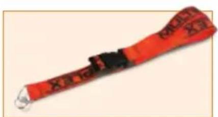
Red and black striped object resembling a wrist strap or grip, with no visible text or symbols.8 5715 Transmitter carrying belt
text_image
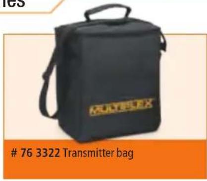
76 3322 Transmitter bag

text_image
MULTIPLEX M-LINK76 3323 Transmitter case
natural_image
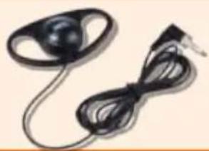
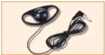
Close-up of a black electronic device with a coiled cable and ear connector (no text or symbols visible)8 5071 Earphones
text_image
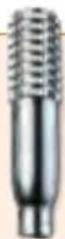
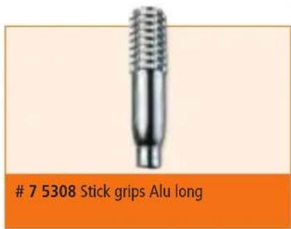
7 5308 Stick grips Alu long
text_image
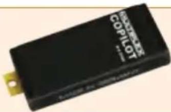
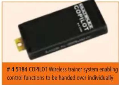
4 5184 COPILOT Wireless trainer system enabling control functions to be handed over individually
text_image
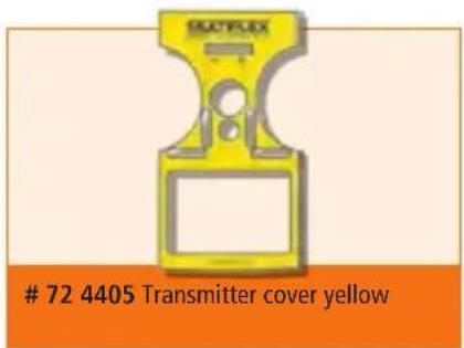
72 4405 Transmitter cover yellow
text_image
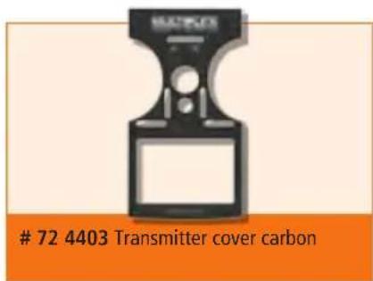
72 4403 Transmitter cover carbon