USER MANUAL BAR122HGN OREGON SCIENTIFIC
Digital Weather Forecaster with Remote Thermo-Hygro Sensor and Radio Controlled Clock
Model: BAR122HGN
User Manual
P/N:086L002706-173 REV1
Digital Weather Forecaster with Remote Thermo-hygro Sensor And Radio Controlled Clock MODEL NO.: BAR122HGN
USER MANUAL
CONTENTS
Introduction 2
Main Features: Main Unit 2
Features: Remote Thermo-hygro
Sensor - THGR228N 4
Before You Begin 4
Battery Installation: Main Unit 5
Battery and Channel Installation:
Remote Unit ....5
Low Battery Warning 6
How to use the Table Stand or Wall Mounting ..... 6
The Reset Button 6
Getting Started 6
How to Check Remote and Indoor
Temperature & Humidity....7
Disconnected Signals 7
Transmission Collision 7
How to Read the Kinetic Wave Display .... 8
Remote Sensor Scanning 8
The Comfort-level Icons 8
P/N:086L002706-173 REV1
Temperature, Humidity & Pressure
Trend Indicators 9
Maximum and Minimum Temperature
And Humidity 9
How to use Channel-1 Temperature/
Humidity Alarm 9
Weather Forecast Function 11
Calendar Clock Display Modes 11
About Radio Reception 11
How to Set the Clock Manually 12
How to Set and arm the Alarms 13
How to Stop an Alarm 13
Precautions 13
Specifications 14
About Oregon Scientific 14
EC-declaration of Conformity 15
Troubleshooting Guide - BAR122HGN 15
INTRODUCTION
Congratulations on your purchase of the Weather forecaster with cable free sensor and radio-controlled calendar clock (BAR122HGN).
this unit has a large four-line liquid crystal display (LCD) for displaying weather forecast information, in/outdoor temperatures and relative humidity, radio frequency (RF) controlled calendar clock, clock display of 2nd time-zone and dual daily alarms. Also, the main unit can support up to three remote sensors.
Other features include weekday display in four abbreviated languages, four-step crescendo alarm and interchangeable clock display modes.
MAIN FEATURES: MAIN UNIT
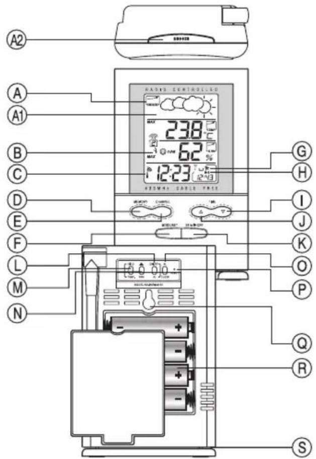
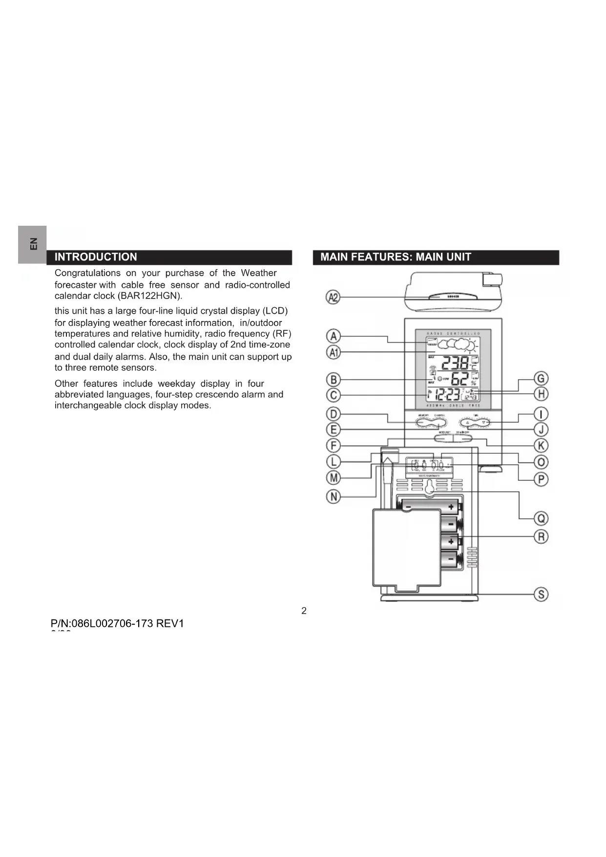
P/N:086L002706-173 REV1
A. FRONT DISPLAY
A four line easy-to-read LCD
Graphically illustrates a weather forecast
A2. [SNOOZE] BUTTON
Activates the 8-minute snooze function when the clock alarm goes off
B. [∅] Battery-low indicator
Activates when the remote-sensor or main unit battery power is low
C. [T] Radio-reception signal
Indicates the condition of radio reception
D. [MEMORY] BUTTON
Displays minimum and maximum temperature and humidity readings, and erases memory data
E. [CHANNEL] BUTTON
Toggles among the remote sensor channels
F. [MODE/SET] BUTTON
Changes the display mode of the clock and alters time/datesetting
G. [ ] / [ 2 Alarm-on iconS
Appears when the alarm is activated
H. [((1))] / [((2))] Alarm iconS
Appears when the alarm time is displayed
I. [TIME ▽] Button
Decreases the value of a setting
J. [TIME △] Button
P/N:086L002706-173 REV1
Advances the value of a setting
K. [24 hr ▶ OFF] BUTTON
Displays the alarm time, or changes the alarm set time
L. [ON/OFF] Button (Temp/% rh alarm)
Enables / disables HI/LO temp alarm and HI/LO % RH alarm
M. [HI/LO] Button (Temp/% rh alarm)
- Set the upper or lower temperature alarm limits of individual channels
- Confirms alarm settings
N. [▲] Button (Temp/% rh alarm)
Sets the readings for the upper or lower temperature and humidity of individual channels
O. [AL clock] Button
Enables or disables the daily alarms
P. [RESET] Button
Returns all settings to default values
Q. Wall-Mount Hole
For mounting the unit on a wall
R. Battery Compartment
Accommodates four (4) UM-3 or "AA" size batteries
S. Removable Table Stand
For standing the main unit on a flat surface
FEATURES: REMOTE THERMO-HYGRO SENSOR - THGR228N
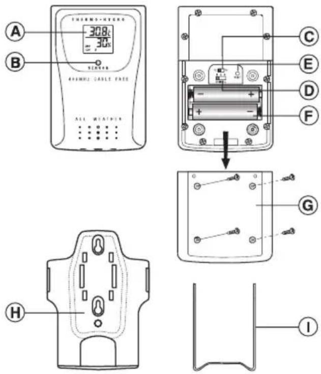
A. Two-line LCD
Displays the current temperature and humidity monitored by the remote unit
P/N:086L002706-173 REV1
B. LED indicator
Flashes when the remote unit transmits a reading
C. ^ C / ^ slide switch
Selects between Centigrade (°C) and Fahrenheit (°F)
D. Channel slide switch
Designates the remote unit Channel 1, Channel 2 or Channel 3
E. RESET
Returns all settings to default values
F. Battery compartment
Accommodates two AAA-size batteries
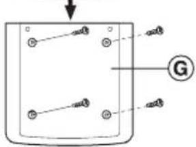
G. BATTERY DOOR
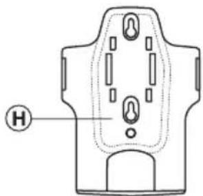
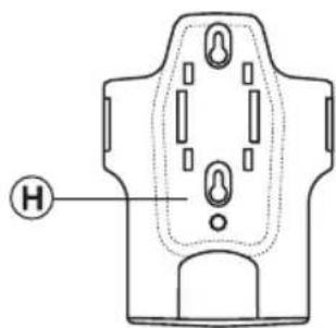
H. Wall-mount holder
Supports the remote unit in wall-mounting
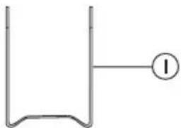
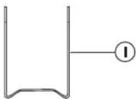
I. Removable table stand
For standing the remote unit on a flat surface
BEFORE YOU BEGIN
For best operation,
- Assign different channels to different remote units.
- Insert batteries for remote units before doing so for the main unit.
-
Place the main unit as close as possible next to the remote unit, reset the main unit after installing batteries. This will ensure easier synchronization between the transmission and reception of signals.
-
Position the remote unit and main unit within effective transmission range, which, in usual circumstances, is up to 100 meters.
NOTE that the effective range is vastly affected by the building materials and where the main and remote units are positioned. Try various set-ups for best result.
Though the remote units are weather proof, they should be placed away from direct sunlight, rain or snow.
BATTERY INSTALLATION: MAIN UNIT
- Gently lift up the tab on the battery compartment door.
- Insert four UM-3 or "AA" size batteries.
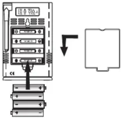
- Replace the battery compartment door.
P/N:086L002706-173 REV1
BATTERY AND CHANNEL INSTALLATION: REMOTE UNIT
The remote thermo-hygro sensor unit uses two (2) UM-4 or "AAA" size batteries.
Follow these steps to install / replace batteries:
- Remove the screws on the battery compartment.
- Select the channel number on the [CHANNEL] slide switch.
- Select the temperature display unit on the ^ C/ ^ F slide switch.
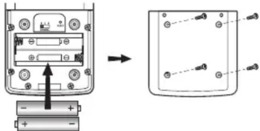
- Insert the batteries strictly according to the polarities shown therein.
- Replace the battery compartment door and secure its screws.
Replace the batteries when the low-battery indicator of the particular channel lights up on the main unit. (Repeat the steps described in section "BEFORE YOU BEGIN")
NOTE that once a channel is assigned to a remote unit, you can only change it by removing the batteries or resetting the unit.
LOW BATTERY WARNING
When it is time to replace batteries, the respective low-battery indicator will show up when the respective channel is selected. The battery level of the main unit will be shown on the indoor temperature when it is running low.
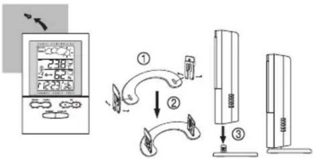
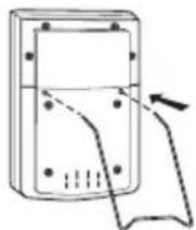
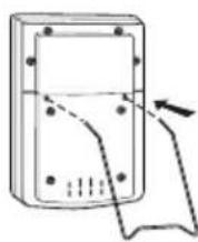
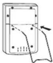
HOW TO USE THE TABLE STAND OR WALL MOUNTING
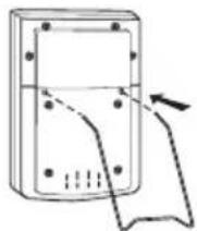
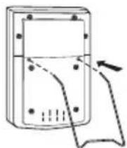
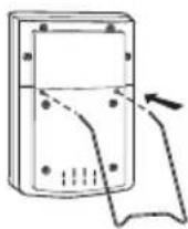
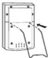
The main unit has a removable table stand, which when connected, can support the unit on a flat surface. Or you can remove the stand and mount the unit on a wall using the recessed screw hole.
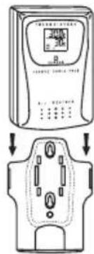
As for the remote unit, it comes with a wall-mount holder and a removable stand. Use either to hold the unit in place.
Main unit
Wall-mount
Table Stand
flowchart
graph TD
    A["Weather System"] --> B["2:38°F"]
    B --> C["4:62°F"]
    C --> D["1:23:5°C"]
    D --> E["Refrigerator"]
    E --> F["Refrigerator with Air"]
    F --> G["Refrigerator with Air"]
    G --> H["Refrigerator with Air"]
    H --> I["Refrigerator with Air"]
    I --> J["Refrigerator with Air"]
P/N:086L002706-173 REV1
Remote unit
Wall-mount
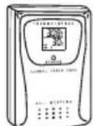
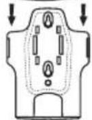
Table Stand
This button is only used when the unit is operating in an unfavorable way or malfunctioning. Use a blunt stylus to hold down the button. All settings will return to their default values.
GETTING STARTED
Once batteries are placed in a given remote sensor unit, it will start transmitting information at 40-second intervals.
Also, for approximately a 3-minute duration, the main unit will automatically search for signals once batteries are installed. Upon successful reception, the individual channel temperature reading will be displayed on the top
line and the respective humidity reading on the bottom line. The main unit will automatically update its readings at about 40-second intervals.
If no signals are received, blanks “---” will be displayed and the kinetic wave icon will not show.
To force a signal search:
- Press and hold [CHANNEL] & [MEMORY] for 2 seconds to enforce a 3-minute search.
This is useful in synchronizing the transmission and reception of the remote and main units.
Repeat this step whenever you find discrepancies between the readings shown on the main unit and that on the respective remote unit.
HOW TO CHECK REMOTE AND INDOOR TEMPERATURE & HUMIDITY
Display of readings from a remote sensor or the main unit is a one-step procedure. The remote sensor channel or the main unit display is indicated in a box under the kinetic-wave icon.
| Kinetic-wave Icon |  | [XXAG] |  | [T47S] |
| Designated Display | Indoor Display | Remote Display Channel 1 | Remote Display Channel 2 | Remote Display Channel 3 |
To display temperature / humidity readings from the main unit:
P/N:086L002706-173 REV1
- Press [CHANNEL] until a dot is displayed in the box under the kinetic-wave.
To display temperature / humidity readings from a remote sensor:
- Press [CHANNEL] until the appropriate remote sensor channel is displayed in the box under the kinetic-wave.
DISCONNECTED SIGNALS
If without obvious reasons the display for a particular channel goes blank, press [CHANNEL] & [MEMORY] to enforce an immediate search.
If that fails, check:
- The remote unit of that channel is still in place.
- The batteries of both the remote unit and main unit. Replace as necessary.
NOTE that when the temperature falls below freezing point, the batteries of outdoor units will freeze, lowering their voltage supply and the effective range.
- The transmission is within range and path is clear of obstacles and interference. Shorten the distance when necessary.
Signals from other household devices, such as door bells, home security systems and entry controls, may
interfere with those of this product and cause temporarily reception failure. This is normal and does not affect the general performance of the product. The transmission and reception of temperature and humidity readings will resume once the interference recedes.
HOW TO READ THE KINETIC WAVE DISPLAY
The kinetic wave display shows the signal receiving status of the main unit. There are three possible forms:
| The unit is in searching mode. |  |
| Transmission data are securely registered. | 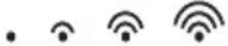 |
| No signal received in search mode. | • |
REMOTE SENSOR SCANNING
The unit can be set to automatically scan and display readings from the remote sensors and indoor readings. When the remote-sensor mode is active, the display will show the readings from one channel for about 4-second and then proceed to the next channel display.
To activate the remote-sensor scanning mode:
- Press and hold [CHANNEL] for 2-seconds.
To deactivate the remote-sensor scanning mode:
- Press either [CHANNEL], [MEMORY], [HI/LO], [▲], [ON/OFF] (TEMP % RH AL)
P/N:086L002706-173 REV1
THE COMFORT-LEVEL ICONS
The comfort level indicators COMFORT, WET or DRY will tell you if the current environment is comfortable, too wet or too dry.
The comfort indicator will appear on the display when the following conditions are satisfied:
| Indicator displays on the unit | Temperature Range | Humidity Range | Shows that the Current Environment |
 COMFORT COMFORT | 20°C to 25°C (68°F to 77°F) | 40%RH-70%RH | Ideal range for both relative humidity and temperature |
 WET WET | -5°C -+ 50°C (23°F - 122°F) | OVER-70%RH | Contains excess moisture. |
| [WDOK]DRY | -5°C -+ 50°C (23°F - 122°F) | Below 40%RH | Contains inadequate moisture |
| No Indicator | Less than 20°C( 68°F) or More than 25°C (77°F) | 40%RH to 70%RH | No comment |
TEMPERATURE, HUMIDITY & PRESSURE TREND INDICATORS
The temperature-trend, humidity-trend and pressure trend indicators show the trends of collected readings. Arrows indicate a rising, steady or falling trend.
| Arrow Indicator |  |  |  |
| Temperature Trend | Rising | Steady Failing |
| Arrow Indicator |  |  |  |
| Humidity Trend | Rising | Steady Falling |
| Arrow Indicator |  |  |  |
| Pressure Trend | Rising | Steady Falling |
NOTE If the readings goes above or below the measuring range of the main unit or the remote unit (stated in specification), the display will show "HHH" or "LLL".
MAXIMUM AND MINIMUM TEMPERATURE AND HUMIDITY
The maximum and minimum recorded temperature and humidity readings will automatically be stored in the memory.
To display the maximum and minimum display memory:
- Select the channel to be checked.
- Press [memory] once to display the maximum temperature and humidity and again the minimum temperature and humidity. The respective indicators, MAX or MIN will be displayed.
To clear the memory:
- Press and hold [MEMORY] for 2-seconds.
If you press [MEMORY] now, the maximum and minimum recordings will have the same values as the current ones until different readings are recorded.
HOW TO USE CHANNEL-1 TEMPERATURE/HUMIDITY ALARM
Upper and lower temperature and humidity limits for channel-1 can be set so that an alarm activates when the limits are exceeded.
The high and low temperature and humidity displays are selected by sequentially pressing HI/LO.
The high-low displays are as follows:
| Sequence Respective Display |
| Pressing HI/LO once Enters HI temperature display |
| Pressing HI/LO twice Enters HI humidity display |
| Pressing HI/LO third time Enters LO temperature display |
| Pressing HI/LO fourth time Enters LO humidity display |
To set a high or low temperature or humidity alarm:
- Press [HI/LO], channel-1 will be displayed.
- Press [A] to set the temperature or humidity limit. Each press will increase increments by one degree or percentage. Press and hold the button for a rapid-scrolling sequence by increments of five.
NOTE The temperature range is from -50^ ( -58^ ) to +70^ ( 158^ ).
If this is the first time you set the limits, the lower limit will start from -50^ ( -58^ ) and the upper limit +70^ ( 158^ ). Other wise, the reading will start from the temperature last selected.
The humidity range is from 2% to 98%.
If this is the first time you set the limits, the lower limit will start from 2% and the upper limit 98% Otherwise, the reading will start from the humidity last selected.
- Repeat the steps to set the upper humidity setting and the lower temperature and humidity settings.
- When finished, press [HI/LO] to set another limit or wait 16-seconds. the unit will automatically return to
P/N:086L002706-173 REV1
the normal display.
The respective HI, LO or both indicators will light up to signify the status of the alarm.
If in another channel other than channel one is selected, when the alarm activates the display will switch to channel-1 and the display will flash. If left untouched, the alarm will activate for a 1-minute. Press [CHANNEL], [MEMORY], [HI/LO], [▲], [ON/OFF] (TEMP % RH AL) to momentarily stop the alarm. The alarm will activate again if the limit continues to exceed the set limit.
NOTE If a second limit is passed while an alarm is active, the first alarm will complete its 1-minute cycle and the alarm will continue to activate for a second minute to indicate that a second limit has been surpassed.
To disable an alarm:
- Enter the setting mode by pressing [HI/LO].
- Then, press [ON/OFF].
The alarm has been disabled and will not sound at the previously set limit.
To disable a sounding alarm:
- Press either [CHANNEL], [MEMORY], [HI/LO], [▲], ON/OFF
WEATHER FORECAST FUNCTION
The unit is capable of detecting atmospheric pressure changes. Based on collected data, it can predict the weather for the forthcoming 12 to 24 hours. The effective range covers an area of 30 to 50 km.
| Indicator displays on the unit |  | 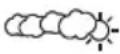 | 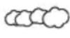 | 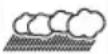 |
| SunnyF | OtegrasyRlady | Cloudy | |
NOTE
- The accuracy of a general pressure-based weather forecast is about 70% to 75%.
- The weather forecasts from this unit are predictions that cover the next 12 to 24 hours. It may not necessarily reflect the current situation.
- The "Sunny" icon, as applies to nighttime, implies clear weather.
CALENDAR CLOCK DISPLAY MODES
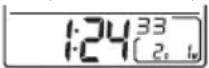
The BAR122HGN supports four time display modes in the sequence of:
MODE 1. Hour-Minute-Second (of local time)
Day-Month (of local time)
P/N:086L002706-173 REV1
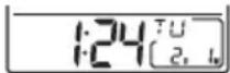
MODE 2. Hour-Minute-Day of the Week (of local time)
Day-Month (of local time)
MODE 3. Hour-Minute-Day of the Week (of local time)
Hour-Minute (of alternate time zone)
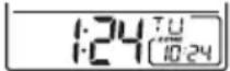
MODE 4. Hour-Minute-Day of the Week (of second time zone)
Day-Month (of alternate time zone)
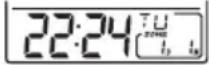
Each press on the [MODE/SET] button will toggle the display in the above order.
NOTE The bottom line of the display will be replaced by the alarm time if the [24] button is pressed.
ABOUT RADIO RECEPTION
The BAR122HGN is designed to automatically synchronize its calendar clock once it is brought within range of the Frankfurt DCF77 radio signal.
When the BAR122HGN is within range, its radio-control
mechanism will override all manual settings.
When the unit is receiving radio signal, the RADIO RECEPTION signal will start to blink. A complete reception generally takes about 2 to 10 minutes, depending on the strength of the radio signal.
When the reception is complete, the RADIO RECEPTION signal will stop blinking. The strength of the reception will remain until the next scanning cycle backs place.
For better reception, place the clock away from metal objects and electrical appliances to minimize interference.
| - Strong |
| - Weak |
| - No signal |
| - Receiving |
If you wish to disable the auto-reception feature, press the [TIME / ▽button for three seconds. The radio reception signal [ ] will disappear. The unit will not
respond to radio signals.
To enable the feature again, press the [TIMEX] button for three seconds.
The radio reception signal [icon] will start blinking to initiate reception automatically.
HOW TO SET THE CLOCK MANUALLY
To set the clock manually, hold [MODE/SET] for three seconds. The hour digits will blink.
Press [TIME] or [TIME/▽] select the hour. Keep pressing the button to increase or decrease the value rapidly.
Press [MODE/SET] to confirm. The minute digits will blink.
Repeat the same procedure to set the minutes, current day, month, display language, weekday and hour offset for the 2nd time zone.
NOTE The time and date are displayed in 24-HOUR clock format. For the language display, you can choose among English (E), German (D), French (F) and Italian (I). Weekday is in the usual sequence of Monday through Sunday.
For the 2nd time zone, which is indicated by the ZONE icon, enter the hour offset using the [TIME / △] and [TIME / ▽] buttons and the BAR122HGN will calculate the second zone-time accordingly.
If there is an item you do not wish to change, simply press [MODE/SET] to bypass the item.
When you are done, press [MODE/SET] to exit. The display will return to the mode last chosen.
HOW TO SET AND ARM THE ALARMS
The BAR122HGN has two alarms, ALARM 1 and ALARM
- They can be invoked together or independently.
To set an alarm:
- Press [24] once to select ALARM 1 or again to select ALARM 2. The last selected time of the alarm will be displayed. If you have never set the alarm before, the time will be displayed as 0:00.
- Press [4] for three seconds. The hour digits will blink.
- Enter the hour using [TIME/△and [TIME/].▽
- Press [24] the minute digits will blink.
- Enter the minutes using [TIME] and [TIME].
- Press [24] the kit. OFFE [ ] icon for the alarm chosen will be displayed indicating the alarm set above is now armed.
You can also arm or disarm an alarm by pressing the [AL CLOCK] button.
When an alarm is armed, it will go off at the set time.
The four-step crescendo function allows the alarm to start off gently and step up its intensity. Without interruption, the alarm will go off for a total of two minutes.
If a second alarm goes off when the first alarm is sounding off, the first alarm will be disabled automatically.
HOW TO STOP AN ALARM
To stop an alarm, you can use either press 24 hr ▶ OFF
P/N:086L002706-173 REV1
] or [ AL CLOCK ] or [ SNOOZE ] button.
Pressing [24h][RLOECK] will stop the alarm, which is still armed and will activate at the set time the following day.
If [SNOOZE] button is pressed to turn off the alarm sound, the alarm will activate again after 8 minutes.
PRECAUTIONS
- Do not subject the unit to excessive force, shock, dust, temperature or humidity.
- Do not cover the ventilation holes with any items such as newspapers, curtains etc.
- Do not immerse the unit in water. If you spill liquid over it, dry it immediately with a soft, lint-free cloth.
- Do not clean the unit with abrasive or corrosive materials.
- Do not tamper with the unit's internal components. This invalidates the warranty.
- Only use fresh batteries. Do not mix new and old batteries.
- Images shown in this manual may differ from the actual display.
- When disposing of this product, ensure it is collected separately for special treatment.
- Placement of this product on certain types of wood may result in damage to its finish for which Oregon Scientific will not be responsible. Consult the furniture
manufacturer's care instructions for information.
- The contents of this manual may not be reproduced without the permission of the manufacturer.
- Do not dispose old batteries as unsorted municipal waste. Collection of such waste separately for special treatment is necessary.
- Please note that some units are equipped with a battery safety strip. Remove the strip from the battery compartment before first use.
NOTE The technical specifications for this product and the contents of the user manual are subject to change without notice.
SPECIFICATIONS
Temperature Measurement
Main unit
Indoor Temperature measurement
Proposed operating range : -5.0^ to +50.0^ (23.0°F to 122.0°F)
Temperature resolution : 0.1°C (0.2°F)
Relative Humidity Operating range : 25% RH to 90% RH
Remote thermo-hygro unit
Proposed operating range : -20.0°C to +60.0°C (-4.0°F to 140.0°F)
Temperature resolution : 0.1°C (0.2°F)
P/N:086L002706-173 REV1
Relative Humidity Operating range : 25% RH to 90% RH
Power
Main unit : use four (4) UM-3 or "AA" 1.5V battery
Remote sensing unit : use two (2) UM-4 or "AAA" 1.5V battery
Weight
Main unit : 216gm (without battery)
Remote sensing unit : 63 gm (without battery)
Dimension
Main unit : 136 x 90 x 35 mm (L x Wx D)
Remote sensing unit : 92 x 60 x 20mm (L x Wx D)
ABOUT OREGON SCIENTIFIC
Visit our website (www.oregonscientific.com) to learn more about Oregon Scientific products. If you're in the US and would like to contact our Customer Care department directly, please visit: www2.oregonscientific.com/service/support
OR
Call 1-800-853-8883.
For international inquiries, please visit: www2.oregonscientific.com/about/international
Hereby, Oregon Scientific, declares that this Digital Weather Forecaster with Remote Thermo-hygro Sensor And Radio Controlled Clock (model: BAR122HGN) is in compliance with the essential requirements and other relevant provisions of Directive 1999/5/EC. A copy of the signed and dated Declaration of Conformity is available on request via our Oregon Scientific Customer Service.

COUNTRIES RTTE APPROVED COMPLIED
All EU countries, Switzerland CH
and Norway N
UBLESHOOTING GUIDE - BAR122HGN
| Trouble | Possible Cause | Remedy |
| “---” is being displayed for Remote data on the display of the Main Unit | (1) Probably due to electromagnetic interference and/or obstacle in-between the Main Unit and Remote Sensor (e.g., double glass protection or reinforced concrete wall); or(2) Batteries of the Remote Sensor are being discharged | (1) (i) Move the Main Unit away from any source of interference such as DECT phone, mobile phone; and/or (ii) Move the Remote sensor nearer to the main unit and start SEARCH mode in the Main Unit(2) Check LED of Remote Sensor. Replace with new batteries if it does not flash in one minute |
| Displayed remote temperature and/or humidity data on the display of the Main Unit are different from those on the display of the Remote Sensor | Another Remote Sensor using the same frequency and same ID code is being in use within the effective area | Place the Remote Sensor closer to the Main Unit. Then reset the Remote Sensor and activate SEARCH mode in the Main Unit |
| The added Remote sensor is not read by main unit | Selected Channel is already used by another Remote sensor | Select another free channel via the Channel switch. Then reset the Remote Sensor and activate SEARCH mod in the Main Unit |
| Displayed Temperature and/or humidity data are different from other measuring instruments | (1)The measurement method is different (2)The area under evaluation is different or being influenced by climate | (1)Use the same instruments with consideration of the tolerance of readings (2)Place the 2 instruments very closely for a time period (no less then 30 minutes), avoiding direct light and air movements |
| The weather forecast icon never changes | Batteries of the Main Unit are being discharged | Replace with mew batteries |
| Comfort level icon is not displayed- Clock time is not correctly set; and/or- Reception icon“Antenna” displays as “No reception” | Temperature and humidity are out of valid rangeThe clock radio signal is not received because: - Electromagnetic in - terfer ence exist, or the Main Unit is located within re-inforced concrete wall or shadowed area location- Orientation of placement is not at optimum position for reception of clock radio signal | Please refer to User’s Manual- Locate the Main Unit far from PC, mobile phone etc and re-locate it near the window sill. Wait at least 24 hours (note: during night-time signal is less attenuate particularly after raining)- The clock radio signal is searched at 1:00, 2:00, 3:00, 9:00, 15:00, 21:00 every day automatically- To force the signal reception please refer to instructions in the User’s manual |
IL PULSANTE RESET
RICERCA DEI SENSORI REMOTI
K. Bouton Alarm Off/On [24 hr ▶ OFF]
INSTALLATION DES PILES:UNITÉ PRINCIPAL
P/N:086L002706-173 REV1
Sonde
Fixation murale
Socle
site: www2.oregonscientific.com/about/international.asp
A. ANZEIGE
H. [((1))] / [((2))] ALARM-SYMBOLE
P. RÜCKSETZ-TASTE [RESET]
E. RÜCKSETZ-TASTE [RESET]
natural_image
Diagram of a device with a hand pointing to a screen and buttons, no text or symbols present
DIE RÜCKSETZTASTE (RESET)
ABSCHALTEN EINES ALARMS
Soporte de Mesa
Exame do sensor remoto ....8
A. DISPLAY FRONTAL
Display de LCD de quatro linhas de fácil leitura
natural_image
Simple line drawing of a U-shaped container with an electrical outlet labeled I (no text or symbols beyond the label)
BOTÃO RESET
EXAME DO SENSOR REMOTO
$$
(C \times L \times P)
$$
Unidade do sensor remoto : 92 x 60 x 20 mm (C x L x P)
SOBRE A OREGON SCIENTIFIC
A. VOORAANZICHT
C. [ ] RADIO-ONTVANGSTSIGNAAL
L. [ON/OFF]-TOETS (TEMP/% RH ALARM)
Schakelt de HI/LO temp en HI/LO% RH alarm aan/uit
M. [HI/LO]-TOETS (TEMP/% RH ALARM)
WAARSCHUWING DAT DE BATTERIJEN BIJNA LEEG ZIJN
Tafelhouder
DE RESET-TOETS
DIGITAL VÄDERSTATION FÖR VÄDERPROGNOS MED THERMO- HYGRO FJÄRRSENSOR OCH RADIOSTYRD KLOCKA
MODELL: BAR122HGN
ANVÄNDARMANUAL
INTRODUKTION
A. HUVUDDISPLAY
natural_image
Technical line drawing of a mechanical component with labeled point H (no text or symbols beyond label)
natural_image
Simple line drawing of a U-shaped container with an electrical outlet labeled 'I' (no text or symbols on the container itself)
A. TVÅRADERS LCD
Bordsstativ
RESETKNAPPEN
© 2007 Oregon Scientific. All rights reserved.
086L002706-173
P/N:086L002706-173 REV1