
YSTSW45 - Subwoofer YAMAHA - Free user manual and instructions
Find the device manual for free YSTSW45 YAMAHA in PDF.

| Product Type | Subwoofer with Active Servo Processing |
| Brand | YAMAHA |
| Model | YSTSW45 |
| Technology | Advanced YAMAHA Active Servo Technology (ANIC circuit) |
| Speakers | 2 x 20 cm (8") cone woofers (JA2162) with magnetic shielding |
| Built-in amplifier | 70 W into 5 ohms |
| Low-pass filter | 50 Hz – 150 Hz (-24 dB/oct.) with HIGH CUT adjustment |
| Frequency response | 30 Hz – 200 Hz (-10 dB) |
| Power consumption | 55 W |
| Power supply | AC 110 – 240 V, 50/60 Hz (depending on model with voltage selector) |
| Dimensions (W x H x D) | 235 x 365 x 318 mm |
| Weight | 9 kg |
| Included accessories | Anti-vibration rubber pads |
| Main functions | HIGH CUT control, VOLUME adjustment, auto standby (AUTO STANDBY), main POWER switch, power indicator |
| Auto standby | Input signal detection; automatically turns on and returns to standby after several minutes without signal |
| Magnetic shielding | Yes, to avoid interference with TVs |
| Connections | Speaker terminals and line input jacks (INPUT 2) |
| Recommended placement | Outside the main speakers, at least 20 cm from walls; use the rubber pads |
| Maintenance and cleaning | Clean with a clean, dry cloth; do not use chemical solvents |
| Safety | Do not expose to rain or moisture; unplug during thunderstorms; do not open the cabinet; leave 20 cm of space around for ventilation |
| After-sales service | Contact an authorized YAMAHA dealer or qualified service center |
Frequently Asked Questions - YSTSW45 YAMAHA
User questions about YSTSW45 YAMAHA
0 question about this device. Answer the ones you know or ask your own.
Ask a new question about this device
Download the instructions for your Subwoofer in PDF format for free! Find your manual YSTSW45 - YAMAHA and take your electronic device back in hand. On this page are published all the documents necessary for the use of your device. YSTSW45 by YAMAHA.
USER MANUAL YSTSW45 YAMAHA
- Explanation of Graphical Symbols
The lightning flash with arrowhead symbol, within an equilateral triangle, is intended to alert you to the presence of uninsulated "dangerous voltage" within the product's enclosure that may be of sufficient magnitude to constitute a risk of electric shock to persons.
The exclamation point within an equilateral triangle is intended to alert you to the presence of important operating and maintenance (servicing) instructions in the literature accompanying the appliance.

1 Read Instructions - All the safety and operating instructions should be read before the unit is operated.
2 Retain Instructions - The safety and operating instructions should be retained for future reference.
3 HeedWarnings - All warnings on the unit and in the operating instructions should be adhered to.
4 Follow Instructions - All operating and other instructions should be followed.
5 Water and Moisture - The unit should not be used near water - for example, near a bathtub, washbowl, kitchen sink, laundry tub, in a wet basement, or near a swimming pool, etc.
6 Carts and Stands - The unit should be used only with a cart or stand that is recommended by the manufacturer.
6A A unit and cart combination should be moved with care. Quick stops, excessive force, and uneven surfaces may cause the unit and cart combination to overturn.
7 Wall or Ceiling Mounting - The unit should be mounted to a wall or ceiling only as recommended by the manufacturer.
8 Ventilation - The unit should be situated so that its location or position does not interfere with its proper ventilation. For example, the unit should not be situated on a bed, sofa, rug, or similar surface, that may block the ventilation openings; or placed in a built-in installation, such as a bookcase or cabinet that may impede the flow of air through the ventilation openings.
9 Heat - The unit should be situated away from heat sources such as radiators, stoves, or other appliances that produce heat.
10 Power Sources - The unit should be connected to a power supply only of the type described in the operating instructions or as marked on the unit.
11 Power-Cord Protection - Power-supply cords should be routed so that they are not likely to be walked on or pinched by items placed upon or against them, paying particular attention to cords at plugs, convenience receptacles, and the point where they exit from the unit.
12 Cleaning - The unit should be cleaned only as recommended by the manufacturer.
13 Nonuse Periods - The power cord of the unit should be unplugged from the outlet when left unused for a long period of time.
14 Object and Liquid Entry - Care should be taken so that objects do not fall into and liquids are not spilled into the inside of the unit.
15 Damage Requiring Service - The unit should be serviced by qualified service personnel when:
A. The power-supply cord or the plug has been damaged; or
B. Objects have fallen, or liquid has been spilled into the unit; or
C. The unit has been exposed to rain; or
D. The unit does not appear to operate normally or exhibits a marked change in performance; or
E. The unit has been dropped, or the cabinet damaged.
16 Servicing - The user should not attempt to service the unit beyond those means described in the operating instructions. All other servicing should be referred to qualified service personnel.
17 Power Lines - An outdoor antenna should be located away from power lines.
18 Grounding or Polarization - Precautions should be taken so that the grounding or polarization is not defeated.
FCC INFORMATION
1. IMPORTANT NOTICE : DO NOT MODIFY THIS UNIT!
This product, when installed as indicated in the instructions contained in this manual, meets FCC requirements. Modifications not expressly approved by Yamaha may void your authority, granted by the FCC, to use the product.
- IMPORTANT: When connecting this product to accessories and/or another product use only high quality shielded cables. Cable/s supplied with this product MUST be used. Follow all installation instructions. Failure to follow instructions could void your FCC authorization to use this product in the USA.
- NOTE : This product has been tested and found to comply with the requirements listed in FCC Regulations, Part 15 for Class "B" digital devices. Compliance with these requirements provides a reasonable level of assurance that your use of this product in a residential environment will not result in harmful interference with other electronic devices. This equipment generates/uses radio frequencies and, if not installed and used according to the instructions found in the users manual, may cause interference harmful to the operation of other electronic devices.
Compliance with FCC regulations does not guarantee that interference will not occur in all installations. If this product is found to be the source of interference, which can be determined by turning the unit "OFF" and "ON", please try to eliminate the problem by using one of the following measures:
Relocate either this product or the device that is being affected by the interference.
Utilize power outlets that are on different branch (circuit breaker or fuse) circuits or install AC line filter/s.
In the case of radio or TV interference, relocate/reorient the antenna. If the antenna lead-in is 300 ohm ribbon lead, change the lead-in to coaxial type cable.
If these corrective measures do not produce satisfactory results, please contact the local retailer authorized to distribute this type of product. If you can not locate the appropriate retailer, please contact Yamaha Electronics Corp., U.S.A. 6660 Orangethorpe Ave, Buena Park, CA 90620.
The above statements apply ONLY to those products distributed by Yamaha Corporation of America or its subsidiaries.
We Want You Listening For A Lifetime
YAMAHA and the Electronic Industries Association's Consumer Electronics Group want you to get the most out of your equipment by playing it at a safe level. One that lets the sound come through loud and clear without annoying blaring or distortion - and, most importantly, without affecting your sensitive hearing.
Since hearing damage from loud sounds is often undetectable until it is too late, YAMAHA and the Electronic Industries Association's Consumer Electronics Group recommend you to avoid prolonged exposure from excessive volume levels.

CAUTION: READ THIS BEFORE OPERATING YOUR UNIT.
- To assure the finest performance, please read this manual carefully. Keep it in a safe place for future reference.
- Install this unit in a cool, dry, clean place, away from windows, heat sources, sources of excessive vibration, dust, moisture and cold. Avoid sources of humming (transformers, motors). To prevent fire or electrical shock, do not expose the unit to rain or water.
- Never open the cabinet. If something drops into the set, contact your dealer.
- Do not use force on switches, controls or connection wires. When moving the unit, first disconnect the power plug and the wires connected to other equipment. Never pull the wire itself.
- Do not attempt to clean the unit with chemical solvents; this might damage the finish. Use a clean, dry cloth.
- Be sure to read the "TROUBLESHOOTING" section regarding common operating errors before concluding that the unit is faulty.
- When not planning to use this unit for long periods of time (i.e., vacation, etc.), disconnect the AC power plug from the wall outlet.
- To prevent lightning damage, disconnect the AC power plug when there is an electrical storm.
- Since this unit has a built-in power amplifier, heat will radiate from the rear panel. Therefore, place the unit apart from the walls, allowing enough space above, behind and on the both sides of the unit to prevent fire and damage. Also, do not position with the rear panel facing down on the floor or other surface.
Be sure to allow a space of at least 20~cm above, behind and on the both sides of the unit.
- Super-bass frequencies reproduced by this unit may cause a turntable to generate a howling sound. In such a case, move this unit away from the turntable.
- Vibration generated by super-bass frequencies may cause images on a TV to be distorted. In such a case, move this unit away from the TV set.
- This unit features a magnetically shielded design, but there is still a chance that placing it too close to a TV set might impair picture color. Should this happen, move this unit away from the TV set.
13.If you hear distortion (i.e., unnatural, intermittent "rapping" or "hammering" sounds) coming from this unit, reduce the volume level. Extremely loud playing of a movie soundtrack's low frequency, bass-heavy sounds or similarly loud popular music passages can damage this speaker system. -
Voltage Selector (General and China Models only) The voltage selector on the rear panel of this unit must be set for your local main voltage BEFORE plugging into the AC main supply. Voltages are AC 110/120/220/240V, 50/60 Hz.
-
Secure placement or installation is the owner's responsibility.
YAMAHA shall not be liable for any accident caused by improper placement or installation of speakers.
IMPORTANT
Please record the serial number of this unit in the space below.
Serial No.:
The serial number is located on the rear of the unit. Retain this Owner's Manual in a safe place for future reference.
WARNING
TO REDUCE THE RISK OF FIRE OR ELECTRIC SHOCK, DO NOT EXPOSE THIS UNIT TO RAIN OR MOISTURE.
FOR CANADIAN CUSTOMERS
TO PREVENT ELECTRIC SHOCK, MATCH WIDE BLADE OF PLUG TO WIDE SLOT AND FULLY INSERT.
THIS CLASS B DIGITAL APPARATUS COMPLIES WITH CANADIAN ICES-003.
For U.K. customers
If the socket outlets in the home are not suitable for the plug supplied with this appliance, it should be cut off and an appropriate 3 pin plug fitted. For details, refer to the instructions described below.
Note: The plug severed from the mains lead must be destroyed, as a plug with bared flexible cord is hazardous if engaged in a live socket outlet.
SPECIAL INSTRUCTIONS FOR U.K. MODEL
IMPORTANT
THE WIRES IN THE MAINS LEAD ARE COLOURED IN ACCORDANCE WITH THE FOLLOWING CODE:
Blue: NEUTRAL
Brown: LIVE
As the colours of the wires in the mains lead of this apparatus may not correspond with the coloured markings identifying the terminals in your plug, proceed as follows: The wire which is coloured BLUE must be connected to the terminal which is marked with the letter N or coloured BLACK. The wire which is coloured BROWN must be connected to the terminal which is marked with the letter L or coloured RED. Making sure that neither core is connected to the earth terminal of the three pin plug.
Caution 4
Features 5
Placement 5
Connections 6
Controls and their functions 9
FEATURES
- This subwoofer system employs Advanced YAMAHA Active Servo Technology which YAMAHA has developed for reproducing higher quality super-bass sound. (Refer to page 12 for details on Advanced YAMAHA Active Servo Technology.) This super-bass sound adds a more realistic, theater-in-the-home effect to your stereo system.
- This unit can be added easily to your existing audio system by connecting to either the speaker terminals or the line output (pin jack) terminals of the amplifier.
Adjusting volume. 10
Advanced YAMAHA Active Servo Technology 12
Troubleshooting 13
Specifications 13
PLACEMENT
A
B
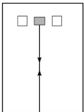
C
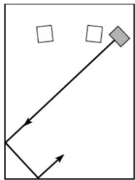
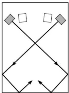
(□:subwoofer,□:main speaker)
One subwoofer will have a good effect on your audio system, however, the use of two subwoofoers is recommended to obtain more presence.
If using one subwoofer, it is recommended to place it on the outside of either the right or the left main speaker. (See fig. A.) If using two subwoofoers, it is recommended to place them on the outside of each main speaker. (See fig. B.) The placement shown in fig. C is also possible, however, if the subwoofer system is placed directly facing the wall, the bass effect may die because the sound from it and the sound reflected by the wall may cancel. To prevent this, face the subwoofer system obliquely to the wall as in fig. A or B.
Note
There may be a case that you cannot obtain enough superbass sounds from this unit when listening at the middle of the room. This is because "standing waves" have developed between two parallel walls and the bass sounds are canceled. In such a case, face the unit obliquely to the wall. It also may be necessary to break up the parallel surfaces by placing bookshelves etc. along the walls.
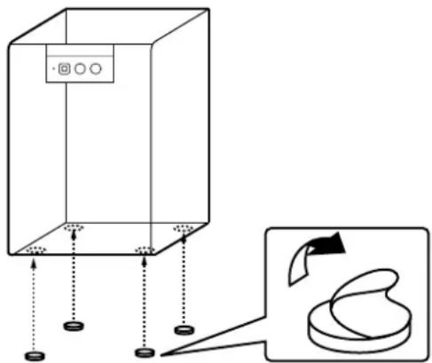
Use the rubber pads
Put the provided rubber pads at the four corners on the bottom of the subwoofer unit to prevent the subwoofer unit moving due to vibrations etc.
CONNECTIONS
Never plug in the subwoofer and other audio/video components until all connections are completed.
- When making connections between this unit and other components, be sure all connections are made firmly and correctly; L (left) to L, R (right) to R, + to + and - to -.
This unit can be connected to either the speaker terminals or the line output (pin jack) terminals of the amplifier. Choose one of the connections shown below according to your audio system. Refer also to the owner's manuals supplied for your audio system.
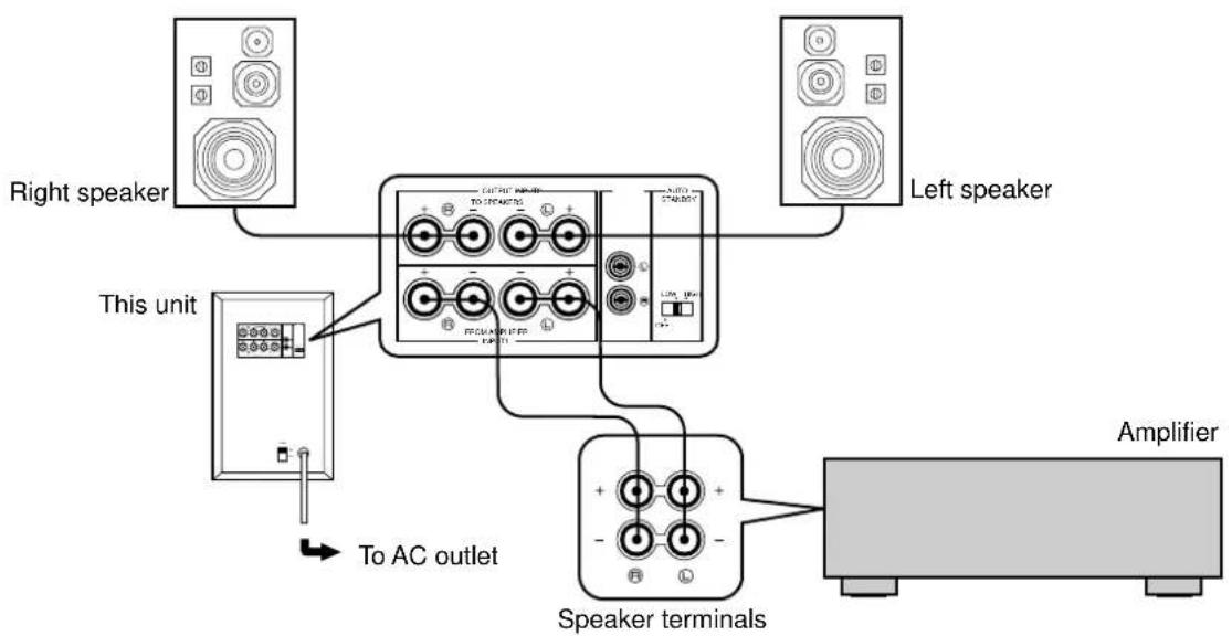
CONNECTING TO SPEAKER TERMINALS OF THE AMPLIFIER
Using one unit
When your amplifier has one set of speaker terminals
- Disconnect your main speakers from the amplifier if connected, and connect them to the speaker terminals of this unit.
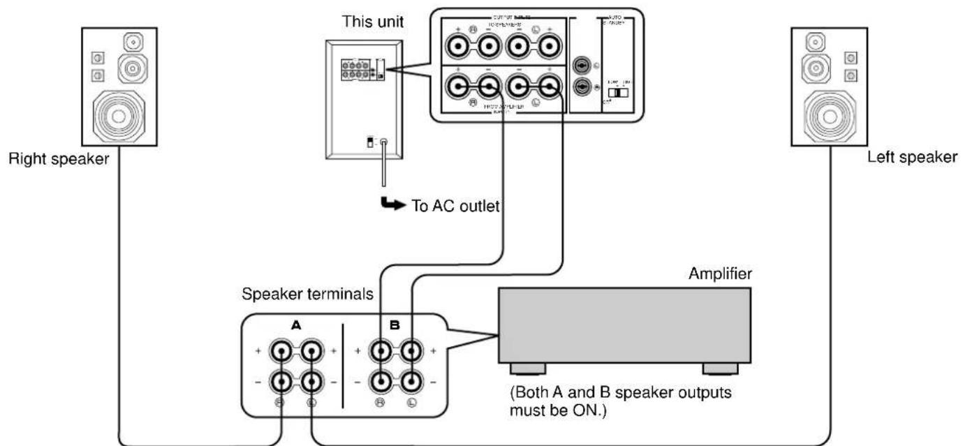
When your amplifier has two sets of speaker terminals
Using two units
Disconnect your main speakers from the amplifier if connected, and connect them to the speaker terminals of this unit.
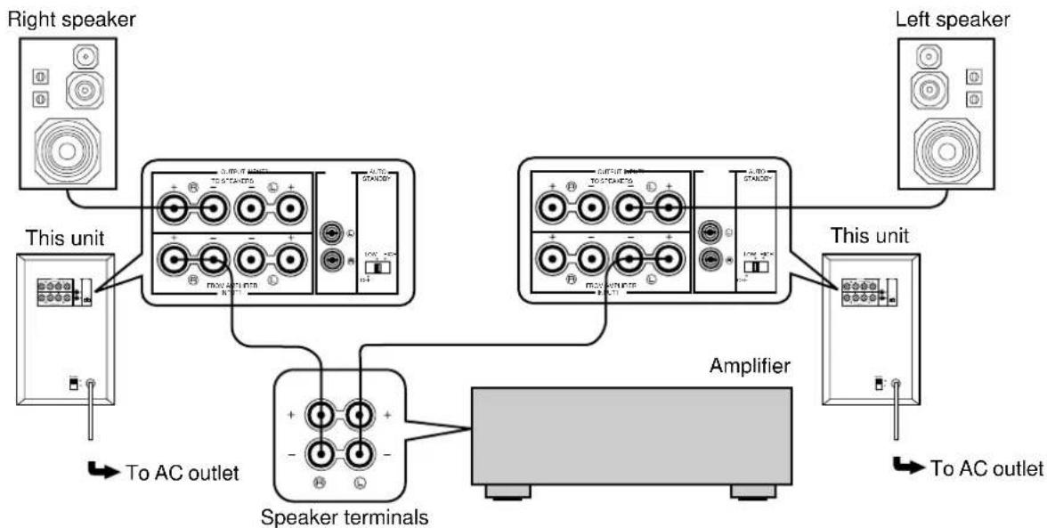
Connecting to this unit's OUTPUT/INPUT terminals
For connections, keep the speaker wires as short as possible. (Cut the excessive wire, if necessary.) If the connections are faulty, no sound will be heard from the speakers. Make sure that the polarity of the speaker wires is correct, by observing + and - markings. If these wires are reversed, the sound will be unnatural and will lack bass.
Do not let the core of the speaker wires touch each other and do not let them touch the metal parts of this unit as this could damage this unit, your amplifier and/or speakers.
How to Connect:
Red: positive (+)
Black: negative (-)
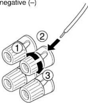
① Unscrew the knob.
② Insert the core of the wire. [Remove approx. 5 mm (1/4") insulation from the speaker wires.]
③ Tighten the knob to secure the wire firmly.
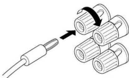
- Banana Plug connections are also possible (except for U.K. and Europe models). Simply insert the Banana Plug connector into the corresponding terminal.
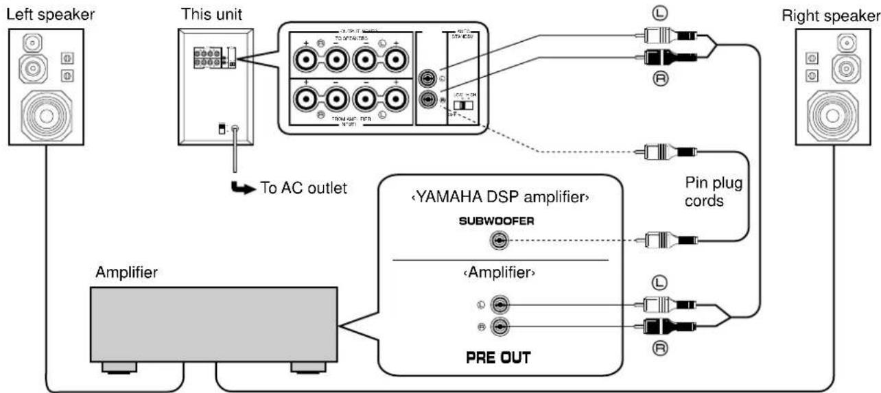
CONNECTING TO LINE OUTPUT (PIN JACK) TERMINALS OF THE AMPLIFIER
- Connect the main speakers to the speaker output terminals of the amplifier.
- Amplifier line output terminals are generally labeled PRE OUT or SUBWOOFER OUT.
To connect with a YAMAHA DSP amplifier, connect the SUBWOOFER (or LOW PASS etc.) terminal on the rear of the DSP amplifier to either the left (L) or right (R) INPUT 2 terminal.
Using one unit
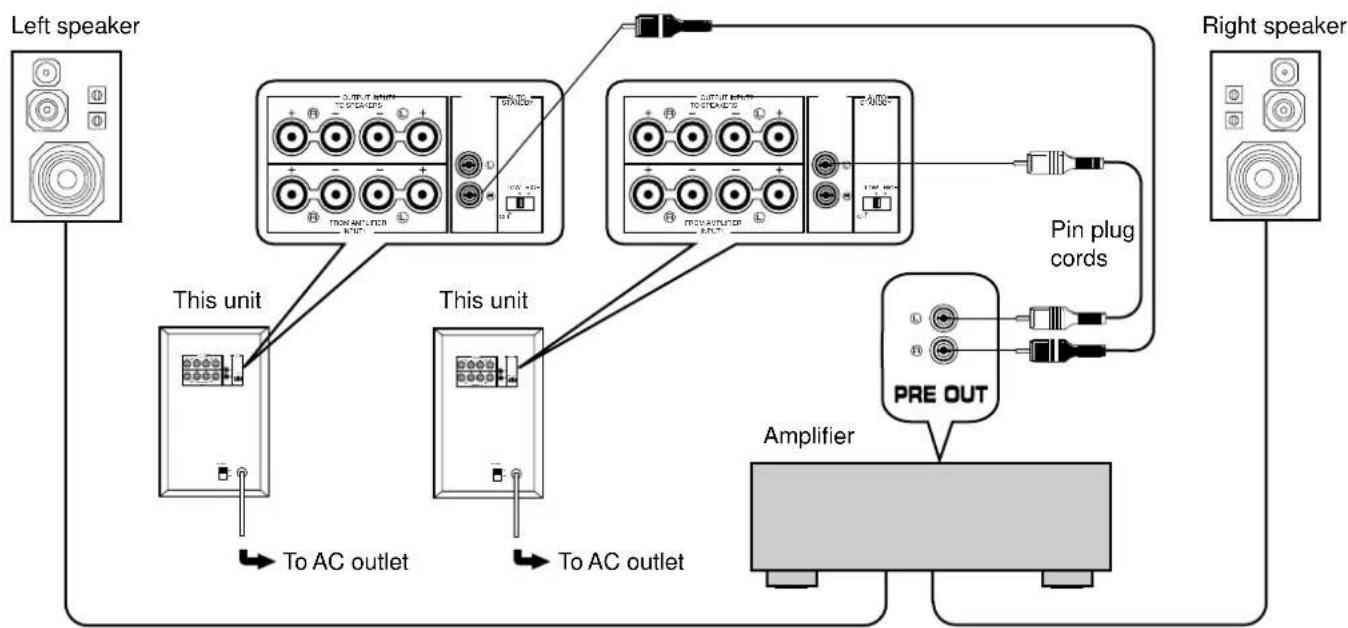
Using two units
Notes on the above connections
- When connected to line output terminals of the amplifier, other speakers should not be connected to the OUTPUT terminals on the rear panel of the subwoofer. If connected, they will not produce sound.
- When connecting this unit to a monaural line output terminal of the amplifier, connect to either the left or right INPUT 2 terminal.
- For using a power amplifier and a preamplifier, the preamplifier must have two sets of PRE OUT terminals. If your preamplifier has only one set of PRE OUT, connect this unit to the speaker terminals. (See page 6.)
CONTROLS AND THEIR FUNCTIONS
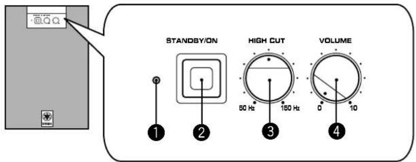
Front panel
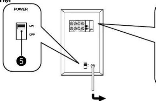
Rear panel
Power indicator
Lights up while this unit is ON.
- If the AUTO STANDBY switch on the rear panel is set to the LOW or HIGH position, this indicator is illuminated dimly when no signal is input to this unit.
STANDBY/ON button
Each press of this button turns the unit on and off (on standby). A small amount of power is always consumed even while this unit is on standby.
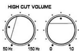
3 HIGH CUT control
Adjusts the high frequency cut off point.
Frequencies higher than the frequency selected with this control are all cut off (and not output).
4 VOLUME control
Adjusts the volume level.
5 Main POWER switch
Normally, leave this switch to the ON position. When you will not use this unit for a long period, set this switch to the OFF position.
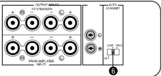
6 AUTO STANDBY switch
With this switch, you can activate the Automatic Standby function. Normally, set the switch to the LOW position.
To cancel this function, set the switch to the OFF position.
- Change the setting of this switch only when the power of this unit is on standby (by setting the STANDBY/ON button to OFF).
Automatic Standby function
When you play a source, the power of this unit turns on automatically by sensing audio signals input to this unit. This unit turns into the standby mode automatically if the source being played is stopped or the low frequency input signal is cut off for several minutes.
This function will operate by sensing a certain level of low frequency input signal. Its sensitivity is high in the HIGH position and low in the LOW position of the AUTO STANDBY switch. In the HIGH position, the power will turn on even with a low level of input signal, but on the other hand this unit may not turn into the standby mode when there is an input signal even if its level is extremely low.
- There may be a case that the power turns on unexpectedly by sensing noise from other appliances. If it occurs, set the AUTO STANDBY switch to the OFF or LOW position.
- The level of low frequency input signal differs with each source, and each different part on the same source. So, this function may not operate properly depending on some sources.
This function is available only when the power of this unit is on (by setting the STANDBY/ON button to ON).
ADJUSTING VOLUME
Adjustment of the HIGH CUT control and the VOLUME control needs to be changed according to the main speakers, listening condition, source, etc.
Front panel
STANDBY/ON HIGH CUT VOLUME
1 Set the VOLUME control to minimum (0).
2 Turn on the other components.
3 Press the STANDBY/ON button to turn on this unit.
4 Play any source and adjust the amplifier's volume control to the desired listening level.
5 Adjust the HIGH CUT control according to the main speakers connected.
Normally, set the control to the main speaker's rated minimum reproducible frequency*. If the desired response cannot be obtained, adjust the control again to your preference.
- The main speaker's rated minimum reproducible frequency can be looked up in the speakers' catalog or owner's manual.
6 Turn up the VOLUME control gradually to adjust the volume balance between this unit and the main speakers.
Normally, set the control to the level where you can obtain a little more bass effect than when this unit is not used. If the desired response cannot be obtained, adjust the control again to your preference.
Once the volume balance between this unit and the main speakers is adjusted, you can adjust the volume of your whole sound system by using only the amplifier's volume control.
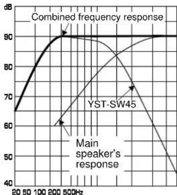
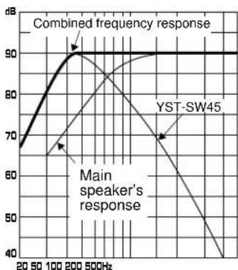
FREQUENCY RESPONSE
This unit's frequency response
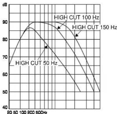
The figures below show the optimum adjustment of each control and the frequency characteristics when this unit is combined with a typical main speaker system.

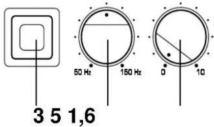
EX.1 When combined with a 3" or 4" (8cm or 10cm) acoustic suspension, 2 way system main speakers
* One graduation of this control represents 10 Hz.
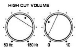
EX.2 When combined with a 5" (13 cm) acoustic suspension, 2 way system main speakers
* One graduation of this control represents 10 Hz.
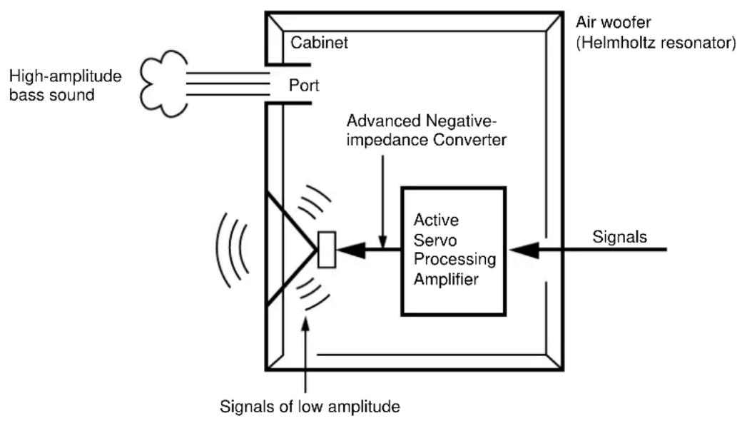
The theory of Yamaha Active Servo Technology has been based upon two major factors, the Helmholtz resonator and negative-impedance drive. Active Servo Processing speakers reproduce the bass frequencies through an "air woofer", which is a port or opening in the speaker's cabinet. This opening is used instead of, and performs the functions of, a woofer in a conventionally designed speaker system. Thus, signals of low amplitude within the cabinet can, according to the Helmholtz resonance theory, be output from this opening as waves of great amplitude if the design is such that the size of the opening and the volume of the cabinet are in the correct proportion to satisfy a certain ratio. In order to accomplish this, moreover, the amplitudes within the cabinet must be both precise and of sufficient power because these amplitudes must overcome the "load" presented by the air that exists within the cabinet.
Thus it is this problem that is resolved through the employment of a design in which the amplifier functions to supply special signals. If the electrical resistance of the voice coil could be reduced to zero, the movement of the speaker unit would become linear with respect to signal voltage, and, to accomplish this, a special negative-impedance output-drive amplifier for subtracting output impedance of the amplifier is used.
By employing negative-impedance drive circuits, the amplifier is able to generate precise, low-amplitude low-frequency waves with superior damping characteristics, and these waves are then radiated from the cabinet opening as high-amplitude signals. The system can, therefore, by employing the negative-impedance output drive amplifier and a speaker cabinet with the Helmholtz resonator, reproduce an extremely wide range of frequencies with amazing sound quality and less distortion.
The features described above, then, are combined to be the fundamental structure of the conventional Yamaha Active Servo Technology.
Our new Active Servo Technology — Advanced Yamaha Active Servo Technology — adopted Advanced Negative Impedance Converter (ANIC) circuits, which allows the conventional negative impedance converter to dynamically vary in order to select an optimum value for speaker impedance variation. With this new ANIC circuits, Advanced Yamaha Active Servo Technology can provide more stable performance and improved maximum sound pressure compared with the conventional Yamaha Active Servo Technology, resulting in more natural and energetic bass reproduction.
If the unit fails to operate normally, check the following points to determine whether the fault can be corrected by the simple measures suggested. If it cannot be corrected, or if the fault is not listed in the SYMPTOM column, disconnect the power cord and contact your authorized YAMAHA dealer or service center for help.
| SYMPTOM CAUSE REMEDY | ||
| The power cannot be turned on. | The power cord is not plugged in, or the Main POWER switch is set to the OFF position. | Plug the power cord into an AC outlet and/or set the Main POWER switch to the ON position. |
| No sound. | The VOLUME control is set to 0. | Turn the VOLUME control to right. |
| Speaker wires are not connected securely. | Connect them securely. | |
| Sound level is too low. | Speaker wires are connected incorrectly. | Connect them correctly; L (left) to L, R (right) to R, + to + and - to - . |
| A source sound with few bass frequencies is played. | Play a source sound with bass frequencies. Set the HIGH CUT control to a higher position. | |
| It is influenced by standing waves. | Reposition the subwoofer or break up the parallel surface by placing bookshelves etc. along the walls. | |
| The unit does not turn on automatically. | The Main POWER switch is set to the OFF position. | Set the Main POWER switch to the ON position. |
| The STANDBY/ON button is set to OFF. | Set the STANDBY/ON button to ON. | |
| The AUTO STANDBY switch is set to the OFF position. | Set the AUTO STANDBY switch to the HIGH or LOW position. | |
| The level of input signal is too low. | Set the AUTO STANDBY switch to the HIGH position. | |
| The unit turns off (on standby) unexpectedly. | The level of input signal is too low. | Set the AUTO STANDBY switch to the HIGH position. |
| The unit turns on unexpectedly. | An influence of noise generated from external equipment etc. | Move the unit farther away from such equipment and/ or change the position of connected speaker wires. Otherwise, set the AUTO STANDBY switch to the OFF position. |
SPECIFICATIONS
Type Active Servo Processing Subwoofer System
Speaker Unit 20 cm (8") cone woofer (JA2162)
magnetic shielding type x 1
Amplifier Output 70 W/5 ohms
High-Cut Filter 50 Hz-150 Hz (-24 dB/occt.)
Frequency Response. 30 Hz-200 Hz (-10 dB)
Power Supply
U.S.A. and Canada models AC 120 V,60 Hz
Australia model.. AC 240 V, 50 Hz
U.K. and Europe models AC 230 V, 50 Hz
General and China models
AC 110/120/220/240 V, 50/60 Hz
(Adjustable with Voltage Selector)
Power Consumption 55 W
Dimensions (W·H·D) 235 mm·365 mm·318 mm
(9-5/16"·14-7/20"·12-1/2")
Weight 9 kg (19 lbs. 13 oz.)
Supplied Accessory Rubber Pads
- Design and specifications are subject to change without notice.
PRECAUTIONS D'USAGE: TENIR COMPTE DES PRECAUTIONS CI-DESSOUS AVANT DE FAIRE FONCTIONNER L'APPAREIL.

- FCC INFORMATION
- IMPORTANT NOTICE : DO NOT MODIFY THIS UNIT!
- We Want You Listening For A Lifetime
- CAUTION: READ THIS BEFORE OPERATING YOUR UNIT.
- IMPORTANT
- WARNING
- FOR CANADIAN CUSTOMERS
- For U.K. customers
- SPECIAL INSTRUCTIONS FOR U.K. MODEL
- FEATURES
- PLACEMENT
- Note
- Use the rubber pads
- CONNECTIONS
- CONNECTING TO SPEAKER TERMINALS OF THE AMPLIFIER
- Using one unit
- Using two units
- Connecting to this unit's OUTPUT/INPUT terminals
- How to Connect:
- CONNECTING TO LINE OUTPUT (PIN JACK) TERMINALS OF THE AMPLIFIER
- Notes on the above connections
- CONTROLS AND THEIR FUNCTIONS
- Front panel
- Rear panel
- Power indicator
- STANDBY/ON button
- HIGH CUT control
- VOLUME control
- Main POWER switch
- AUTO STANDBY switch
- Automatic Standby function
- ADJUSTING VOLUME
- FREQUENCY RESPONSE
- This unit's frequency response
- EX.1 When combined with a 3" or 4" (8cm or 10cm) acoustic suspension, 2 way system main speakers
- EX.2 When combined with a 5" (13 cm) acoustic suspension, 2 way system main speakers
- SPECIFICATIONS
- PRECAUTIONS D'USAGE: TENIR COMPTE DES PRECAUTIONS CI-DESSOUS AVANT DE FAIRE FONCTIONNER L'APPAREIL.
Brand : YAMAHA
Model : YSTSW45
Category : Subwoofer