61808 - Paint spray Chapin - Free user manual and instructions
Find the device manual for free 61808 Chapin in PDF.

User questions about 61808 Chapin
0 question about this device. Answer the ones you know or ask your own.
Ask a new question about this device
Download the instructions for your Paint spray in PDF format for free! Find your manual 61808 - Chapin and take your electronic device back in hand. On this page are published all the documents necessary for the use of your device. 61808 by Chapin.
USER MANUAL 61808 Chapin
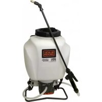
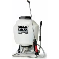
PRETREAT & DE-ICE Backpack Sprayer
Use and Care Manual
Chapin International, Inc
P.O. Box 549
700 Ellicott St.
Batavia, NY 14021-0549 U.S.A.
1-800-950-4458
www.chapinmfg.com
CHAPIN
PRETREAT
&-DE-ICE
Commercial Backpack Sprayer
4.0G / 15L
MODEL 61808
[Unreadable]
Model 61808 • 4G/ 15L
WARNING
Carefully Read These Instructions Before Use
WARNING: Improper use or failure to follow instructions can result in explosive failure causing serious eye or other injury. For safe use of this product you must read and follow all instructions. Do not leave a pressurized sprayer in the hot sun. Heat can cause pressure build-up resulting in possible explosion. Do not store or leave solution in tank after use. Always wear goggles, gloves, long sleeve shirt, long pants and full foot protection when spraying. Never use any tool to remove pump if there is pressure in the pressure chamber. Never pressurize sprayer by any means other than the original pump. Do not attempt to modify this sprayer. Replace parts only with manufacturer's original parts. Never spray flammable, caustic, acidic, chlorine, bleach or other corrosive solutions or heat, pressure, or gas producing chemicals. Always read and follow chemical manufacturer's instructions before use with this sprayer as some chemicals may be hazardous when used with this sprayer. SK 1158-1
SK 1158-1
WARNING: Handling the brass parts of this product will expose you to lead, a chemical known to the State of California to cause birth defects and other reproductive harm.
Wash hands after handling.
CAUTION
- PRE-USE CHECK: Before each use check tightness of hose nut to be sure hose is securely attached to the shut-off assembly. Insure hose is securely attached to the pump outlet by tightening hose nut. Insure that all nozzle and wand connections are tight. Insure the three bolts (underside of base) used to attach the piston cylinder are tight.
- Do Not exceed a tank solution temperature of 120^ / 49^ .
NOTE: The tank and hose may have residual water in it due to quality testing performed on the sprayer.
APPLICATIONS & USE FOR YOUR SPRAYER
Avoid using a sprayer for general cleaning purposes if plant protection or herbicide chemicals have already been used in the sprayer. If a sprayer has been used for plant protection or as an herbicide, clean the sprayer completely (see cleaning section) before using.
Plant Food: Use different spray patterns for optimum foliage feeding or for fungicide and pesticide application.
Herbicides: Reduce weeds and unwanted plants but avoid using the same sprayer for plant feeding or protection without thoroughly cleaning (see cleaning section) the sprayer first.
General Household Use: Apply detergents, cleaning solutions, warm water (do not exceed 120^ F/ 49^ C) or nontoxic household cleaning chemicals for carpets, floors, walls, glass, counter tops and ceilings. DO NOT use sprayer that has been used with herbicides, pesticides or other toxic chemicals for household applications.
General Outdoor Use: Use the sprayer for cleaning windows or with a detergent for general purpose cleaning.
SPRAYER COMPONENTS & USE INFORMATION
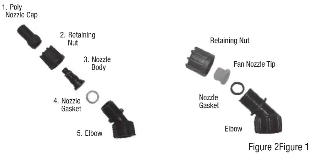
NOZZLE ASSEMBLY
Figure 1
Unscrew the nozzle cap (1) from the nozzle body (3) with retaining nut (2) fastened tightly to the elbow (5). Unscrew the retaining nut (2). Push the nozzle body (3) with the nozzle gasket (4) out of the retaining nut (2). To reinstall the nozzle, reverse the above instructions.
Figure 2
Unscrew the retaining nut from the elbow and push the fan nozzle tip and gasket out of the retaining nut. To reinstall the nozzle, reverse the above instructions.
SPRAYER COMPONENTS & USE INFORMATION, Continued
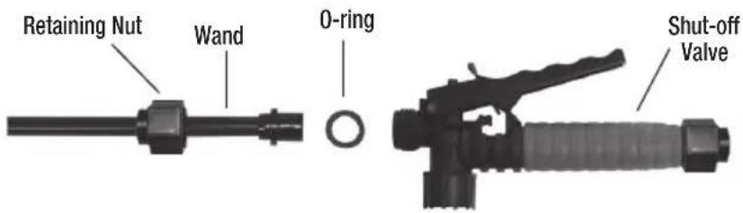
WAND ASSEMBLY
- Make sure the o-ring is installed on the end of the wand. Insert the wand into shut-off valve.
- Turn and tighten the retaining nut clock-wise onto the shut-off valve.
text_image
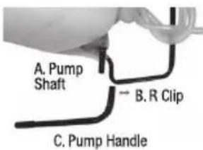
Retaining Nut Wand 0-ring Shut-off ValveINSTALLING THE PUMP HANDLE
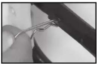
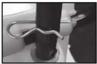
The pump handle can be mounted on either side of the pump shaft (A). To install the pump handle place the handle (C) over the shaft (A) aligning the pump handle hole and shaft hole. Push the straight side of the cotter pin (B) through the aligned hole as shown in figure 1 thru 3.
text_image
A. Pump Shaft B. R Clip C. Pump Handle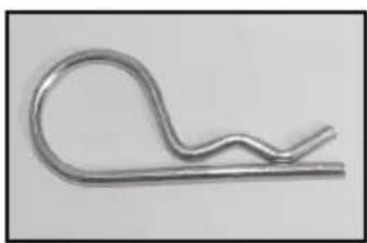
natural_image
Metallic wire spring or hook component with curved and straight ends (no text or symbols)Figure 1 R Clip
natural_image
Close-up of a hand holding a metal wire, partially visible against a dark background (no text or symbols)Figure 2 Line up holes
natural_image
Close-up of a metallic hook securing a black cylindrical object (no text or symbols visible)Figure 3 Slide clip through holes
INSTALLING THE SHOULDER STRAP
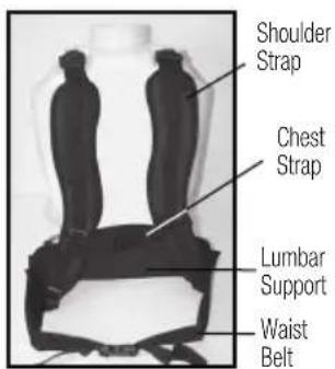
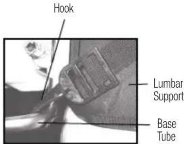
The backpack strap is provided with multiple features including shoulder strap, chest strap, waist belt and lumbar support. (figure 1). The top the shoulder strap is attached to the top of the tank and is removable. The hook from the lumbar support attaches to the base tube on the bottom of the tank (figure 2).
text_image
Shoulder Strap Chest Strap Lumbar Support Waist BeltFigure 1 Strap Assembly
text_image
Hook Lumbar Support Base TubeFigure 2 Hook Attachment
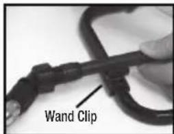
WAND CLIP
The wand can be attached to the metal frame using the wand clips.
text_image
Wand Clip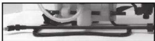
natural_image
Close-up of a mechanical device with a coiled cable and attached pipe (no visible text or symbols)SPRAYER COMPONENTS & USE INFORMATION, Continued
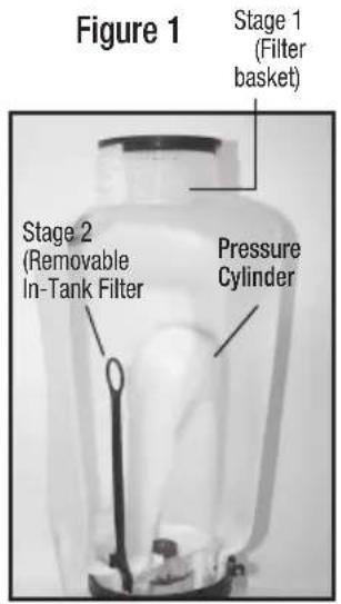
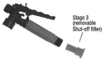
3 STAGE FILTERING SYSTEM
This backpack sprayer is equipped with a 3 stage filtering system (see figure 1). Stage 1 is a filter basket incorporated into the tank opening where fluid is added. Stage 2 filter is located at the inlet of the pressure cylinder. Stage 2 is a removable In-Tank filter. Stage 3 is a removable filter incorporated into the shut-off assembly. Periodic cleaning of these filters is recommended to insure consistent fluid flow through the sprayer. This will also reduce sprayer component wear.
The stage 3 filter is a removable filter incorporated into the inlet side of the shut-off valve (see section “disassembling and repairing the shut-off valve”). Make sure pressure is released before detaching the hose from the shut-off. It is best to have no or minimal fluid in the pressure cylinder before removing and reinstalling the stage 3 shut-off filter as fluid can leak from the hose.
text_image
Figure 1 Stage 1 (Filter basket) Stage 2 (Removable In-Tank Filter) Pressure CylinderFigure 2 Stage 2 (removable In-Tank filter)
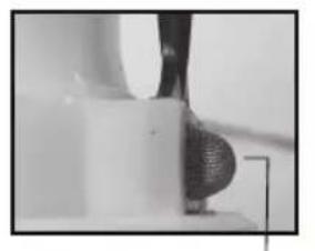
natural_image
Close-up of a mechanical component with a textured spherical part inserted into a base (no visible text or symbols)Guide edge facing away from pressure cylinder
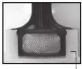
natural_image
Close-up of a black mechanical component with a mesh grille (no visible text or symbols)Guide edge on pressure cylinder
text_image
Stage 3 (removable Shut-off filter)FILLING THE SPRAYER
Make sure the filter basket is in place to keep debris from entering the tank.
Determine the amount of mixture needed for your application. Add the proper amount of water to the tank. Add the proper amount of chemical to the tank (check the chemical label for proper ratio of chemical). Stir mixture in tank with a clean utensil (like a paint stirrer). The tank will hold the 4-gallon (15.1L) capacity plus the chemical.
It is not necessary to completely fill the sprayer tank with each use. You can fill the tank with only the amount needed for each application.
Always follow the manufacturer's instructions included on their product label.
SPRAYER COMPONENTS & USE INFORMATION, Continued
HELPFUL SPRAYING INFORMATION
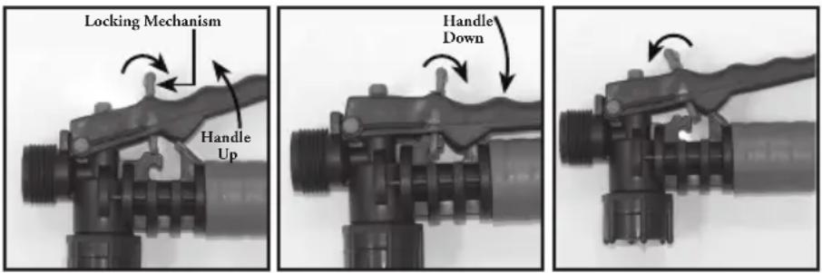
Use RAPID pump strokes to prime the pump. You will know the pressure chamber is filling with liquid when you feel firm resistance from the pump. The air in the pressure chamber is compressed from repeated strokes. By pressing the hand lever on the shut-off, the valve opens. For safety lock-off feature (no-spraying), pull up on handle and move red locking mechanism into lock-off position as shown in fig. 1. To disengage, pull up on handle and return red locking mechanism to neutral position as in fig. 3. For lock-on feature (continuous spraying), push down on handle and move red locking mechanism into lock-on position as shown in fig. 2. To disengage, push down on handle and return red locking mechanism to neutral position as shown in fig. 3.
LOCK-ON POSITION NEUTRAL POSITIONLOCK-OFF POSITION
text_image
Locking Mechanism Handle Up Handle DownFigure 1 Figure 2 Figure 3
For easy pump action use the END of the pump handle. The amount of liquid delivered during spraying depends on the rate of pump stroke. The fan nozzle tip is rated at .4 gpm at 40psi. This is the nominal operating pressure of the sprayer.
Note: If you experience a rapid drop in pressure, drain the sprayer completely and pump the handle with an empty tank. The pressure chamber will fill with the required volume of air to repressurize. Perform this procedure from time to time as routine maintenance.
POWDER-BASED CHEMICALS
Powder-based chemicals (powder mixed with liquids to make the spraying agent) are usually abrasive and can cause wear. When you use a powder-based chemical in your sprayer, make sure it is thoroughly dissolved in the liquid solution. Thoroughly clean and flush the sprayer with water to extend the life of the sprayers parts.
CLEANING
1) Always empty the sprayer and clean the tank thoroughly after each use.
2) Pump the sprayer handle until all of the contents and air exit through the nozzle (minimum of 30 strokes).
3) Fill tank half way with water and pump the water out as explained in step 2 (repeat several times as necessary).
Other Cleaning Hints:
- Improper spray distribution usually means the nozzle is clogged, remove the nozzle and clean it.
- Soap can be added to the water to clean the tank.
- Do not use strong cleaning agents or abrasives.
- If you use a chemical agent to clean the tank follow the manufacturer's recommendations for the disposal of the waste water.
- Follow the chemical manufacturers instructions for clean up.
STORING / MAINTAINING YOUR SPRAYER
- The sprayer should be stored out of direct sunlight in a cool dry space.
- Before freezing weather make sure to drain all liquid in the tank, pump, pressure cylinder, hose, shut-off valve, wand and nozzle, to avoid liquid expansion and cracking in the sprayer components (See “Cleaning” section). Lock the shut-off valve in the “open” position.
- When service is required call your nearest dealer and always insist on original manufactured replacement parts.
- Inspect the hose, wand, pump, tank and shut-off valve for wear, damage or leaks on a regular basis and repair defects promptly.
| Symptom | Possible Reason | Correction |
| Difficulty actuating the pump lever and/or Upper valve plate sticks Clean or replace valve plate | ||
| pump handle moves itself back up. Piston cylinder outlet passage clogged Clean piston cylinder outlet passage | ||
| Little or no resistance during Damaged/worn/dirty/upper and or lower valve plate Clean or Replace Valve Plate repeated pumping - no pressure. Damaged /worn upper o-ring on piston Replace O-ringPiston Collar or piston cylinder assembly is worn Replace Collar or Piston cylinder assembly | ||
| Too much resistance after just a few Not enough air cushion in the pressure Release pressure in pressure chamber pumping strokes but pressure only lasts chamber Remove the hose & drain pressure briefly.Upper valve plate damaged/worn/dirty Clean or replace upper valve plate | ||
| Upward pumping action is more difficult Vent hole is cloggedClear the vent hole in cap | ||
| and/or pump handle moves itself | Lower valve plate sticks | Clean or replace the valve plate |
| backdown. | Clogged filter | Clean in tank filter |
| Piston cylinder intake clogged | Clean piston cylinder intake | |
| When the handle is pulled up it moves itself back down | Valve Plate sticking | Clean or replace valve plate |
| Leaks at Piston Cylinder | Damaged/worn/Dirty Collar | Clean or Replace Piston Collar |
| Damaged Piston Cylinder | Replace Piston Cylinder | |
| Damaged Piston | Replace Piston | |
| Shut-off leaks | Connections loose | Tighten connection |
| Worn or damaged shut-off | Rebuild or replace the shut-off valve | |
| Wand assembly leaks | Connections loose | Tighten connection |
| Damaged or worn o-ring/gasket | Replace o-ring/gasket | |
| Nozzle assembly leaks | Connections loose | Tighten connection |
| Damaged or worn o-ring/gasket | Replace o-ring/gasket | |
| Leak between pump assembly and tank | Pump clamp loose | Tighten clamp |
| O-ring worn or damaged | Replace pressure chamber o-ring | |
| Hose leaking at tank outlet | Hose clamp loose | Tighten clamp |
| Hose leaking at shut-off | Connection loose | Tighten retaining nut |
| Damaged or worn o-ring/gasket | Replace o-ring/gasket | |
DISASSEMBLING AND REPAIRING THE PISTON PUMP
text_image
C B AFigure 1
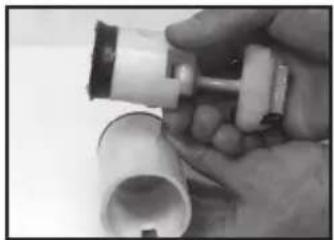
1) Remove the cotter pin and pump handle. With the pump facing towards you lay the unit on its back (Figure 1). Loosen the hose clamp and remove the sprayer hose. Caution: There could be residual liquid in the hose and pressure cylinder. Remove the nut and bolt from the protective cap and remove the cap (ref: figure 9). Rotate the pump shaft in order to reach two lever bolts(A). Using an allen wrench, remove the lever bolts. Pull the piston assembly (B) out of the piston cylinder (C).
natural_image
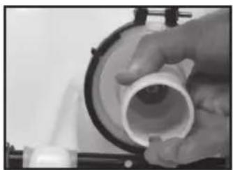
Close-up of a hand holding a white PVC pipe fitting (no text or symbols visible)Figure 2
2) Remove the piston cylinder assembly by turning the piston cylinder counter-clockwise when viewing the sprayer from the bottom. Caution: The piston cylinder may have sharp edges.
natural_image
Close-up of a hand holding a white plastic tool with a cylindrical component, no visible text or symbolsFigure 3
3) Check for vertical scratches on the inside of the piston cylinder and the piston. If one or both are scratched replace them.
text_image
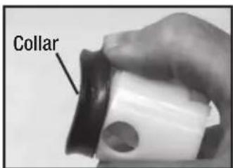
CollarFigure 4
4) To replace the collar, push it off of the crown of the piston with your thumb. You will see form fitted slots to install the new collar on to the piston crown.
text_image
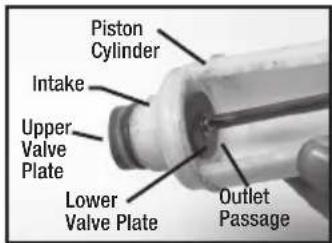
Piston Cylinder Intake Upper Valve Plate Lower Valve Plate Outlet PassageFigure 5
5) There are 2 valve plates on the piston cylinder, one on the inside of the cylinder and one on the outside top. The valve plates are held in place with a screw and washer and can be removed and replaced using a Phillipshead screw driver. The 2 o-rings can be removed and replaced as well. Insure that the o-rings are positioned in the o-ring grooves in the piston cylinder.
text_image
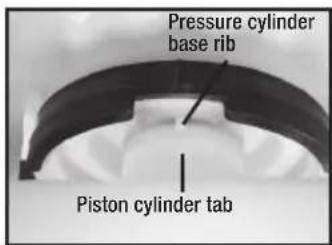
Pressure cylinder base rib Piston cylinder tabFigure 6
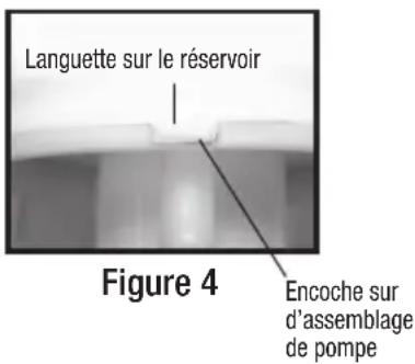
6) Grease the 2 O-rings on the piston cylinder (do not get any grease on the valve plate) and screw the piston assembly into the pressure cylinder base. Screw the piston cylinder clockwise until tight and the bottom O-ring is no longer visible. When properly placed, the tab on the piston cylinder will line up with the rib on the pressure cylinder base.
natural_image
Close-up of hands using a tool to adjust or install a small object, no visible text or symbolsFigure 7
7) Apply Petroleum jelly to the inside of the piston cylinder wall and on the collar, and reinstall the piston assembly into the piston cylinder.
natural_image
Close-up of a hand adjusting a white cylindrical object with black bands (no visible text or symbols)Figure 8
8) Insert the piston at an angle with the leading edge of the collar placed over the slot in the piston cylinder. Bolt the piston assembly to the pump shaft using the lever bolts.
text_image
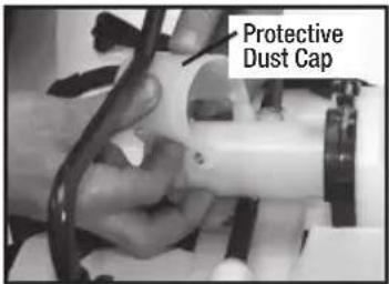
Protective Dust CapFigure 9
9) Replace the protective dust cap. Tighten the nut and bolt. Reinstall the pump handle. Replace the hose and firmly secure the hose clamp in place.
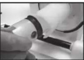
DISASSEMBLING AND REPAIRING THE PUMP ASSEMBLY
- Release the pressure from the sprayer and remove all liquid from both the pressure chamber and tank.
- Remove hose.
- Remove the In-tank filter from the pressure chamber.
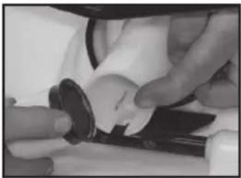
- Remove 2 bolts attaching the pivot lever to the pump shaft and remove piston assembly (fig. 2a & 2b).
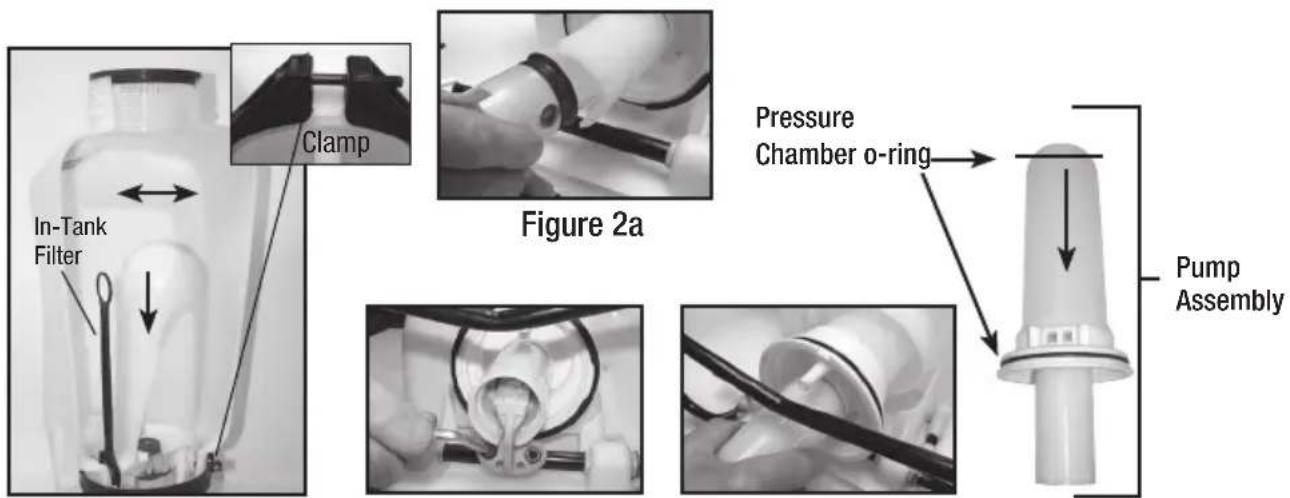
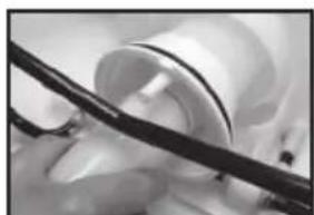
- Remove the large clamp holding the pressure chamber and tank together (fig 1).
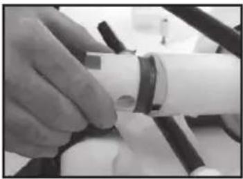
- Rock the pressure chamber back and forth and push down to free it from the tank (fig 1).
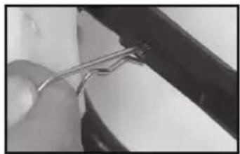
- Once freed the entire pump assembly can be removed by maneuvering it through the base frame (fig 3a & 3b).
text_image
In-Tank Filter Clamp Figure 2a Pressure Chamber o-ring Pump AssemblyFigure 1
natural_image
Close-up of gloved hands holding a small black object with a dark ring (no visible text or symbols)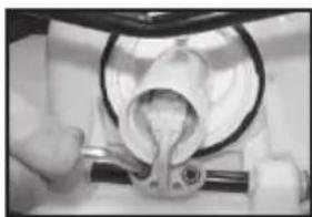
natural_image
Close-up of a mechanical component with a curved pipe fitting and a ring, being handled by gloved hands (no visible text or symbols)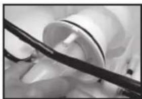
natural_image
Close-up of a medical procedure with surgical tools and tubing (no visible text or symbols)Figure 2b Figure 3a Figure 3b
text_image
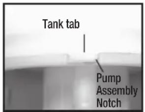
Tank tab Pump Assembly NotchFigure 4
- The pressure chamber o-ring can also be replaced. DO NOT stretch the o-ring over the bottom flange. Assemble the o-ring over the top of the chamber. Apply petroleum jelly to the o-ring before reinstalling pump assembly into the tank (fig. 3b).
- Reassemble backwards from step 6 thru 2, performing each step in reverse. Note: there is a notch/tab combination in the pump assembly/tank to be used for alignment (fig. 4).
DISASSEMBLING AND REPAIRING THE SHUT OFF VALVE
natural_image
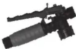
Black-and-white photo of a firearm with lever and barrel (no visible text or symbols)Figure 1
1) Assembled shut-off valve (Figure 1).
natural_image
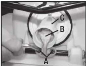
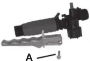
Mechanical device with a cylindrical component and a base plate, labeled A (no text or symbols on the device itself)Figure 2
2) Remove the retaining pin (A) (Figure 2) place the notched end of the retaining pin on a hard surface and push down. Remove the retaining pin and slide the handle off the valve.
text_image
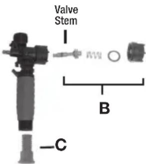
Valve Stem B -CFigure 3
3) Remove the retaining nut (o-ring attached), spring, and valve stem (B) (Figure 3). Replace worn parts. Lubricate the O-rings and reassemble by reversing the steps above. Place the handle groove in the slotted area of the valve stem and make sure the locking clip is positioned in the neutral position (see "Helpful Spraying Information" section). Insert the retaining pin. Push down on the handle a few times to distribute the lubricant evenly. Check filter (C) in end of shut-off valve for debris. Remove filter and flush with water to clean out.
REPLACEMENT PARTS ORDER INFORMATION
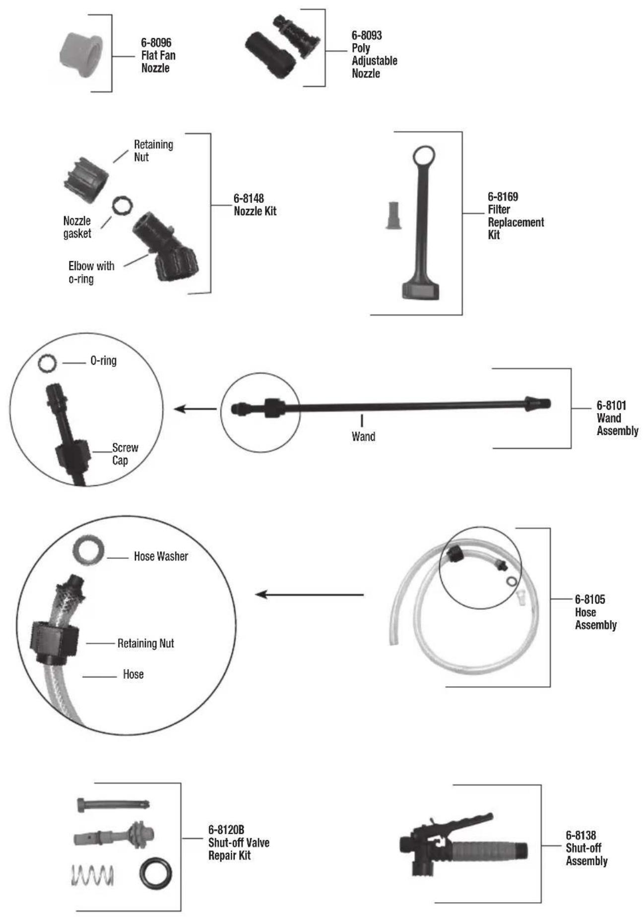
REPLACEMENT PARTS ORDER INFORMATION

Congratulations!
You have just purchased a quality Chapin product.
Register Your Sprayer Online@ www.chapinmfg.com/warranty.asp
PRETREAT &
DE-ICE
Pulverizador
de mochila
natural_image
Metallic hook or spring-like object with a curved handle and looped end (no text or symbols)natural_image
Close-up of a hand holding a metal wire or wire attached to a black surface (no text or symbols visible)natural_image
Close-up of a mechanical component with a metallic hook and black rod (no visible text or symbols)natural_image
Close-up of a mechanical device with a curved black bracket and attached cable (no visible text or symbols)natural_image
Close-up of a mechanical component with a textured surface and a small protrusion (no visible text or symbols)natural_image
Close-up of a black mechanical component with a mesh grille (no visible text or symbols)natural_image
Mechanical component with a curved arrow indicating rotation or assembly (no visible text or symbols)Figura 1 Figura 2 Figura 3
natural_image
Close-up of a hand holding a white cylindrical object, possibly a pipe or component (no visible text or symbols)Figura 2
natural_image
Close-up of a hand holding a white plastic tool with a cylindrical component (no visible text or symbols)Figura 3
natural_image
Close-up of hands performing a manual task with a small object on a surface (no visible text or symbols)Figura 7
natural_image
Close-up of a hand adjusting a wristband on a white object (no visible text or symbols)Figura 8
natural_image
Close-up of a mechanical component being handled with hands (no visible text or symbols)Figura 2b Figura 3a Figura 3b
natural_image
Close-up of mechanical components with a black tool interacting with a white cylindrical component (no visible text or symbols)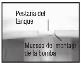
natural_image
Black-and-white photo of a firearm with a long barrel and lever (no visible text or symbols)Figura 1
natural_image
Mechanical device with a cylindrical component and a base, labeled A (no text or symbols on the device itself)Figura 2
natural_image
Metal hook-shaped object with a looped end, no text or symbols visibleFigure 1 Goupille fendue
natural_image
Close-up of a hand holding a metal wire or wire, partially visible against a dark background (no text or symbols)natural_image
Close-up of a metallic hook securing a black cylindrical object (no text or symbols visible)natural_image
Close-up of a mechanical device with hoses and a central component (no visible text or symbols)SYSTÈME DE FILTRAGE À 3 ÉTAPES
natural_image
Close-up of a mechanical component with a textured spherical part inserted, no visible text or symbolsnatural_image
Close-up of a black mechanical component with a textured surface and a pointed top (no visible text or symbols)natural_image
Close-up of a mechanical valve assembly with a curved arrow indicating rotation (no text or symbols visible)Figure 1 Figure 2 Figure 3
natural_image
Close-up of a hand holding a white cylindrical pipe through a mechanical component (no visible text or symbols)Figure 2
natural_image
Close-up of a hand holding a white plastic tool with a cylindrical component (no visible text or symbols)Figure 3
natural_image
Close-up of hands using a medical or laboratory tool to adjust a white object with a black cap (no visible text or symbols)Figure 7
natural_image
Close-up of hands holding a wristwatch and wrist strap (no visible text or symbols)Figure 8
natural_image
Close-up of hands holding a black mechanical component (no visible text or symbols)natural_image
Close-up of a mechanical component with a curved pipe fitting (no visible text or symbols)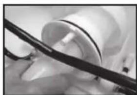
natural_image
Close-up of a medical procedure with surgical tools in use (no visible text or symbols)Figure 2b Figure 3a Figure 3b
natural_image
Black-and-white photo of a firearm with a long barrel and lever (no visible text or symbols)Figure 1
natural_image
Mechanical device with a lever and attached component, labeled A (no text or symbols on the device itself)Figure 2