
RWM450 - Smoke detector ABUS - Free user manual and instructions
Find the device manual for free RWM450 ABUS in PDF.
User questions about RWM450 ABUS
0 question about this device. Answer the ones you know or ask your own.
Ask a new question about this device
Download the instructions for your Smoke detector in PDF format for free! Find your manual RWM450 - ABUS and take your electronic device back in hand. On this page are published all the documents necessary for the use of your device. RWM450 by ABUS.
USER MANUAL RWM450 ABUS

Security Tech Germany
KONFORMITAT GEM. VFDB 14/01 31 (Q
ENTSORGUNG 31
DANKE!
EN 14:604:2005J AC:2008

1772-CPR-150087

HAFTUNGSAUSSCHLUSS
Security Tech Germany
User manual Wireless smoke alarm device with heat alarm Funktion
GB

CONTENTS
THANK YOU! 35
FUNCTION 36
ALARM AND INDICATION SOUNDS 36
LED SIGNALS 38
CHOOSING A LOCATION 39
SETTING UP AND ESTABLISHING THE NETWORK
- SETTING UP 40
- NETWORK SETUP 42
MOUNTING 52
ADHESIVE MOUNTING 52
- DRILLED HOLE MOUNTING 54
GENERAL SAFETY GUIDELINES 55

Possible damage to property

Note on installation
CONFORMITY AS PER VFDB
(GERMAN FIRE PROTECTION
ASSOCIATION 14/01 63
DISPOSAL 63
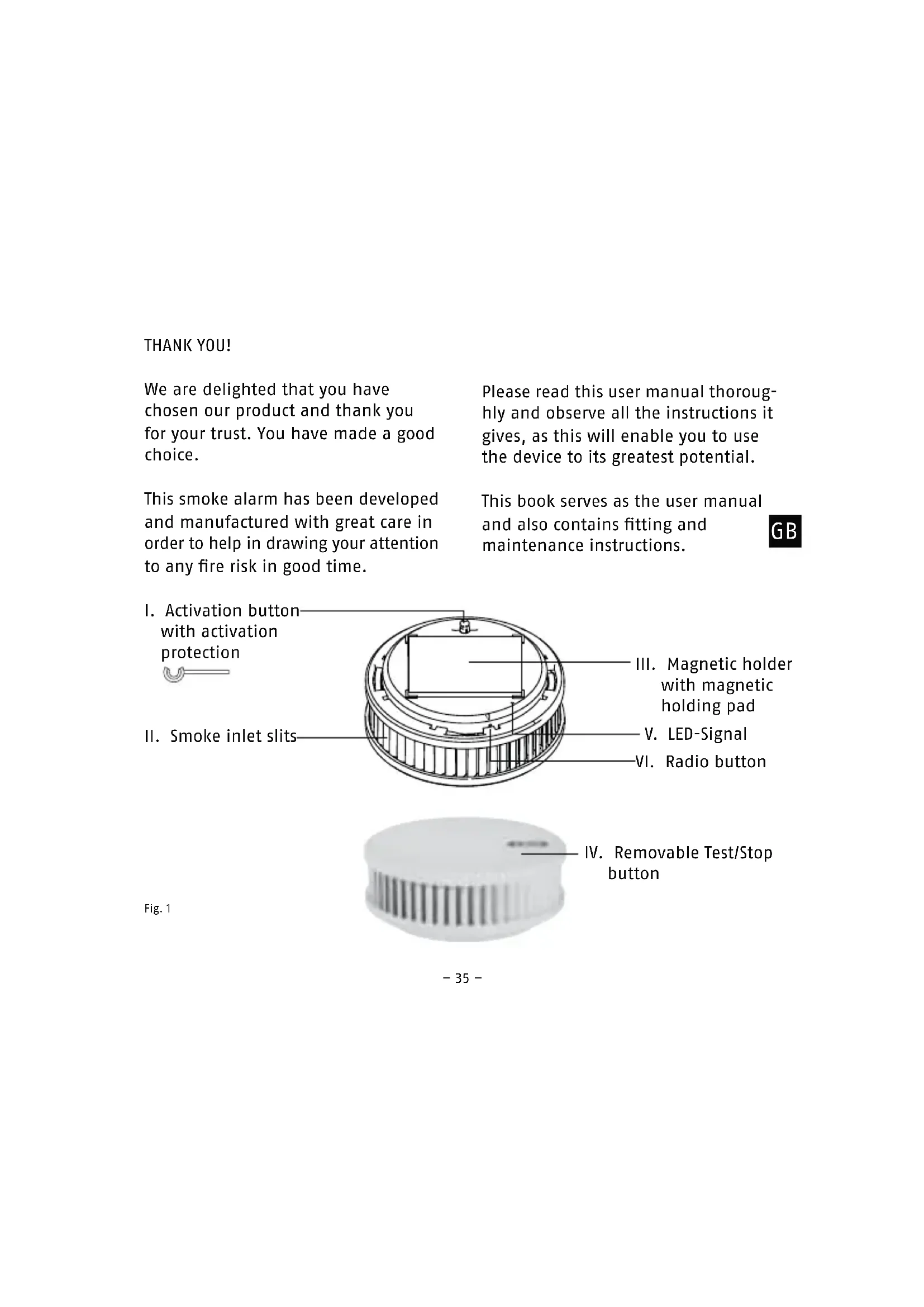
THANK YOU!
We are delighted that you have chosen our product and thank you for your trust. You have made a good choice.
This smoke alarm has been developed and manufactured with great care in order to help in drawing your attention to any fire risk in good time.
Please read this user manual thoroughly and observe all the instructions it gives, as this will enable you to use the device to its greatest potential.
This book serves as the user manual and also contains fitting and maintenance instructions.
GB
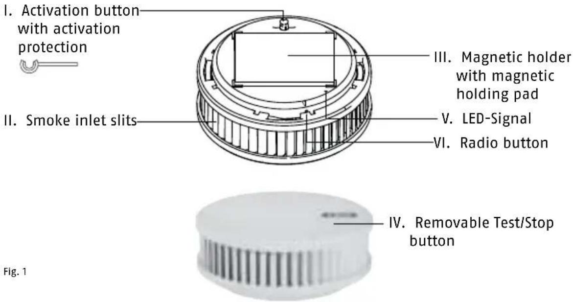
Fig. 1
METHOD OF FUNCTIONING
Heat warning function:
- Heat warning function is triggered at 60^ C
- Single beep every second
ALARM AND INDICATION SOUNDS
Indication sounds:
When the device is activated a simple sound is emitted once
(short beep)
Volume:
Cause: Activation sound

Indication sounds:
When the Test/Stop button is pressed a single sound (long beep) is issued.
Volume:
Cause: Test sound

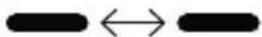
Alarm sounds:
A two-part signal is issued (short beep followed by longer beep) every second.

0,5 seconds
Volume:
Cause: Smoke alarm

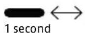
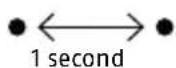
Alarm sounds:
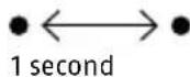
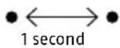
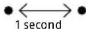
A single tone is issued every second (short beep).

1 second
Volume:

Cause: Temperature alarm
Silencing the alarm sounds

10 min
All alarm sounds can be temporarily deactivated by pressing the Test Stop button (Fig. 1, item d) (smoke alarm and temperature alarm: 10 min.).
Indication sounds:
A single tone is issued every 90 seconds (short beep).

90 seconds
Volume:

Cause:
Low battery warning
If the smoke alarm issues one of the two indication sounds described above, the device will remain capable of providing
its warning function for a maximum of 60 days and must therefore be replaced before this remaining 60-day period expires.
Indication sounds:
A double tone is issued every 90 seconds (short beeps).

90 seconds
Volume:
Cause: Device is contaminated

Silencing the indication sounds:

All indication sounds can be temporarily deactivated by pressing the Test/Stop button (Fig. 1, item d) (low battery and contamination indications: 24 hours).
Damage to the device invalidates the warranty and guarantee
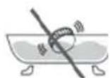
Do not immerse the unit in water.
No battery replacement is possible (see "General Safety Information").
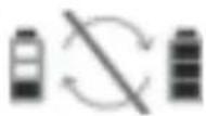
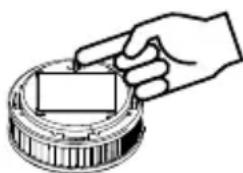
This is a sealed system; only the cover can be changed.

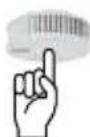
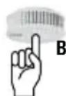
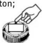
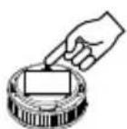
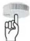
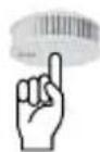
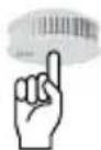
Press cover to silence the signal.
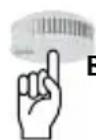
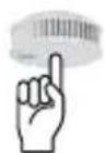
Pull out red activation button to switch unit off.
LED SIGNALS
LED:

Signal: short yellow pulse (lights only very briefly)
Meaning: Testing in progress, please wait!
LED:

Signal: yellow steady signal
Meaning: During start-up when radio button is pressed
LED:

Signal: long (slow)
yellow
intervals
Meaning: Networking mode (for approx. 10 minutes)
LED:
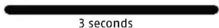
3 seconds
Signal: green steady signal
Meaning: An action has been completed successfully
LED:
3 seconds
Signal: red steady signal
Meaning: Error
- Do not install in environments that are subject to drafts (e.g. fan, ventilation...) or bathrooms
Unit is suitable for kitchens, if false alarms due to steam can be ruled out - At the highest installation position on the ceiling in the middle of the room (not on walls)
- Minimum distance of 50 cm from walls, furniture, lamps
- Monitored area maximum 60 m² with maximum ceiling height of 6 m
- Distance between two devices maximum 15 m
- Corridor length maximum 7.5 m
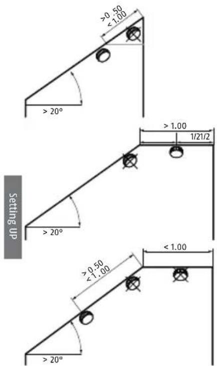
Not onto the ceiling beam for ceiling beams with a height of >20cm but 1 device per intermediate space up to a maximum of 36~m^2 in surface area - For ceiling beams with a height of < 20cm , a detector at the centre of the room (also possible on ceiling beam)
Platforms/galleries <16 mand at least 2 m long and wide: 1 detector
- over 16m^2 : install additional detectors
- Roof slopes (slopes below 20^ are considered flat ceilings):
In the event of a fire, this device quickly detects the build-up of smoke and also the associated rise in temperature in the room. In order to warn you in good time, it then emits a loud alarm sound. If you decide that there is no real need to escape the building you can temporarily deactivate this signal (for approx. 10 minutes), or temporarily disable it before sounding, by gently pressing the Test/Stop button (Fig. 1, IV). We recommend that you then provide good ventilation to the room to prevent the alarm being triggered again.
SETTING UP AND ESTABLISHING THE NETWORK
Setting Up
Notes on networking the radio-interlinked smoke alarm (abbreviated here to RISA or "alarm"):
The alarm should only be activated as described in this manual:
Activation and setup of radio groups:
The alarms must ONLY be set up
- singly
- one after another
- in direct proximity to their intended installation position (in the room in which each unit will be used).
Do not network alarms that are less than 1 m apart - signal overlap - faults in network setup
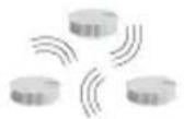
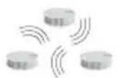
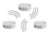
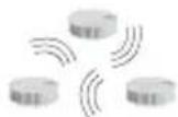
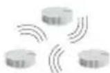
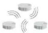
Radio group: at least two, maximum 15 RISAs
- All networked units of the same radio group will issue an alarm when at least one RISA of this group detects smoke or temperatures typical of fire
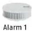
The first alarm to be activated is temporarily assigned the "master" function (of establishing and managing the radio group) - This first-activated alarm should be fitted in a central position (e.g. landing or corridor)
Common radio group: is also a normal radio group
where one or more radio groups (e.g. a flat) are linked to a specific radio group (e.g. stairway), this becomes a common radio group.
- All interlinked alarms of a radio group trigger an alarm (e.g. in a flat)
- All alarms of the common radio group (e.g. stairway) will also, after a delay period of roughly 60 seconds, issue alarms if they are linked as a common radio group to the radio group of the flat
- Alarms are transferred only from the radio group (e.g. flat) to the common radio group (e.g. stairway)
- There is no transfer in the other direction, from the common radio group (e.g. stairway) to the radio group (e.g. flat)
- Up to 14 radio groups can be interlinked to a common radio group
- A radio group cannot be linked to a common radio group and also with other radio groups
Setting Up the "Master":
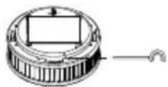
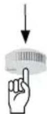
Remove the black activation pin (which also acts as activation protection); but this will still be needed.
Press red activation button

Beep 1x

LED 1 second
Signal: short yellow pulse (lights only very briefly)
Meaning: Testing in progress, please wait!
LED 1xred
Meaning: No other RISA yet found as this is the first one to be started up. Once the red LED goes out, continue as follows to network other units to this RISA:
Network setup
Setting up other RISAs; Connection Mode and creating a Radio Group
- When setting up the network always ensure to link each additional alarm to the master.
- Set up each additional RISA in a position close to its final installation position
On the master already set up:
- Press black activation pin into marked opening and hold until LED lights yellow
- Pull back activation pin, then:

LED
Signal: short yellow pulse (lights only very briefly)
Meaning: Testing in progress, please wait!
LED
Signal: green steady signal
Meaning: Master function is now on
LED
1 seconds

Signal: long yellow intervals (slow)
Meaning: Networking mode (for approx. 10 minutes)
You now have 10 minutes in which to activate the connection mode of an additional alarm and so to extend the radio group. With each further RISA added, this period extends by a further 10 minutes for all devices.
Setting up other RISAs; Connection Mode and creating a Radio Group
Remove the black activation pin (which also acts as activation protection); but this will still be needed.
Press red activation button

Beep

LED
Signal:
short yellow (lights only very
Meaning: Testing in progress, please wait!
LED

Signal: green steady signal
Meaning: Connection has been established with at least one RISA.

LED

Signal: long yellow intervals (slow)
Meaning: Connection mode active; additional RISAs can be added to the radio group
For this see section: Setting up other RISAs; Connection Mode and Creating a Radio Group
If LED then lights red:
- Alarm is outside radio range of other devices
- Indirect connection via repeating or routing also not possible
- Time allowed for connection mode has expired
If this occurs please check:
- Are other alarms still in connection mode (LED flashing yellow at regular intervals)?
- If not: see section "Extending the Radio Group, Entering Connection mode and Repeat Connection Attempts".

Completing Setup of Radio Group
Setup of the radio group is automatically ended 10 minutes after activation of the last planned alarm. After this, none of the units' LEDs give any signal. Connection mode can also be ended immedi
ately by briefly pressing the radio button with the black activation pin on any alarm within the group. This causes the LEDs of all devices to go out.
Radio Group Function Test
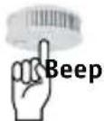
Press and hold the Test/Stop button for 2-3 seconds to invoke a self-test on this device:
Beep
1x
Press for 2 - 3 seconds

Holding the Test/Stop button down longer, until the second beep, issues a radio signal that initiates a self-test for all alarms within the radio group. This test should be performed regularly, every 3-6 months, to check the radio group.
Beep
1

Press for 2 - 3 seconds until second beep
Repeat Connection Attempts
First, deactivate the unit completely:
- Pull out red activation button
- Press and hold Test/Stop button 2-3 seconds
- Pull out red activation button; radio setup re-starts.
Extending the Existing Radio Group/ Re-entering Connection Mode

Once 10 minutes have passed during setup of the radio group in which some alarms are still in connection mode, these devices must be put into connection mode again if still further devices are to be added to the radio group:
- Press black activation pin into marked opening and hold until LED lights yellow; continue to hold until LED blinks yellow.
- Pull activation pin back, then, for all alarms added to the radio group thus far:
LED
Signal: short yellow pulse (lights only very briefly)
Meaning: Connection mode is activated on all RISAs of this radio group
After 5-15 seconds:
LED
Signal: green steady signal
Meaning: Connection mode is activated on all RISAs of this radio group
LED
1 second
Signal: long yellow interval (continuous)
Meaning: Networking mode (for approx. 10 minutes)
Removing Assignment to a Radio Group, Resetting RISA (restore factory settings)
If it is necessary to change the assignment of an alarm to a particular radio group, all stored information must be deleted (i.e. the unit restored to factory settings).

-
Pull out red activation button
-
Press and hold Test/Stop button 2 - 3 seconds
- Press black activation pin into marked opening and hold until LED lights yellow
- Pull back activation pin, then:
LED

3 seconds
Signal: green steady signal
Meaning: Reset successful, alarm restored to factory settings
Setting up a Common Radio Group

Example:
One radio group is initially installed in each flat and in the stairway as described.
Ground Floor Radio Group max. 15 units
1st Floor Radio Group max. 15 units
2nd Floor Radio Group max. 15 units
3rd Floor Radio Group max. 15 units
The Radio Group as Common Radio Group
max. 14 radio groups possible plus CRG stairway

Activate the group you wish to be the common radio group (e.g. in stairway):
- Press black activation pin into marked opening of one of the Stairway group alarms and hold until LED lights yellow; continue to hold until LED blinks yellow.
- Pull activation pin back, then, for all alarms added to the radio group thus far:
LED flashes periodically for approx. 10 minutes
W
- On the next alarm to the stairway from the Ground Floor radio group, press the black activation pin:
LED

Signal: short yellow pulse (lights only very briefly)
Meaning: Testing in progress, please wait!
LED
3 seconds
Signal: green steady signal
Meaning: Connection successful between Ground Floor radio group and Stairway radio group
Now repeat this procedure with the second, third and fourth radio groups to link these with the Stairway radio group.
Completing Setup of a Common Radio Group
Once all the radio groups of the flats are linked to the Stairway radio group, exit connection mode as follows:
-
On any alarm in the Stairway radio group
-
Press radio button with black activation pin for 2 seconds
-
Stairway radio group is set as common radio group
-
All LEDs on connected alarms go out
Common Radio Group Connection Test
Press and hold Stairway common radio group for 2-3 seconds
Beep 1x

Beep issued only on this alarm
Wait approx. 10 seconds until 2nd beep:
1x

Beeps on all alarms in the common radio group but not in the other radio groups!
This test should be performed regularly, every 3-6 months, to check the common radio group.
Connection Test between Radio Group and the Common Radio Group
e.g.Ground Floor radio group
Press and hold approx. 20 seconds Hold down on this alarm until 3rd beep (do not release earlier!)
Beep 3x10 seconds

1st beep: Test on this device:
2nd beep: Test of connection to radio group - no beep on the other alarms in the radio group
3rd beep: Test of Connection to Common Radio Group:
1 x beep on all alarms in the common radio group
Please note:
This test must be performed separately for each alarm connected to the common radio group. This test should be performed regularly, every 3 - 6 months, to check the connection to the common radio group.

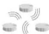
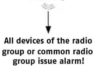
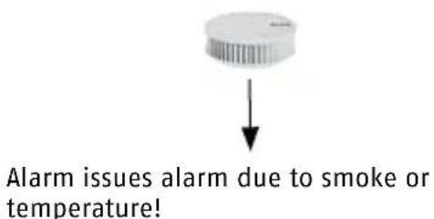
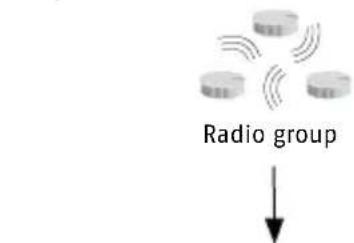
Alarm Forwarding/Alarm Stop
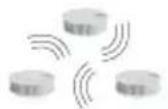
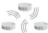
Example: To forward an alarm within radio range
- Unit issues alarm due to smoke or temperature
- Forwards directly after 15 seconds by radio to all other connected alarms in radio group
All devices of the radio group or common radio group issue alarm
dnn pnnn

Example:
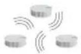
Forwarding Alarm Outside Radio Range
- Alarm 1 issues alarm due to smoke or temperature
- Forwards after 20 seconds by radio to all other connected alarms in radio group
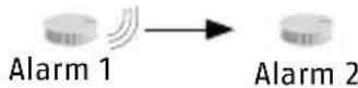
Range OK Signal is forwarded directly to Alarm 2
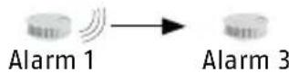
Range OK Signal is forwarded directly to Alarm 3
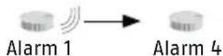
EDistance is too great. No direct forwarding of alarm. Alarm 3 becomes a repeater. Signal is forwarded to Alarm 4 indirectly
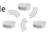
AForwarding of an Alarm from Radio Group to a Common Radio Group
Forwards after 15 seconds by radio to all other connected alarms in radio group!
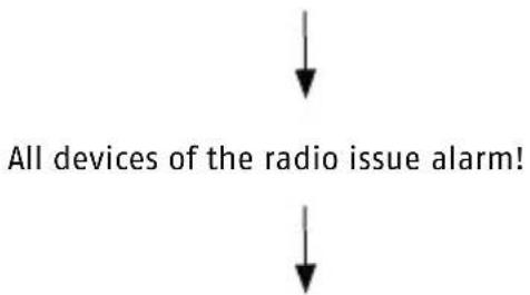
-
Forwards after 60 seconds by radio to all other connected alarms in common radio group
-
Forwarding is solely from radio group to common radio group, i.e. not from stairway to flat(s)!
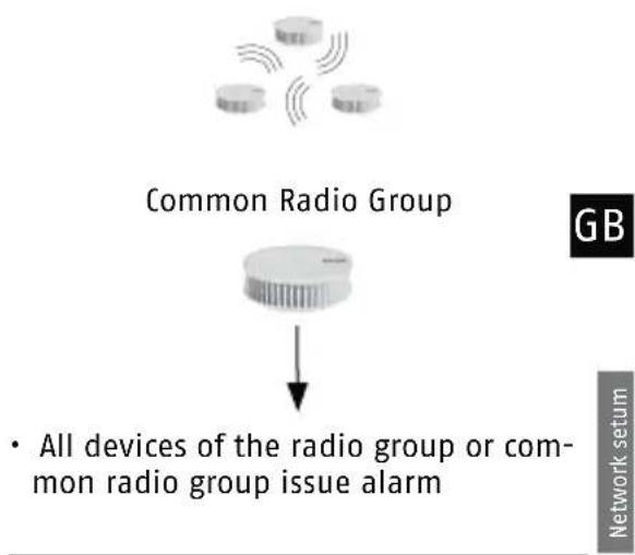
For when an alarm sounds but you are absolutely certain that there is no fire!
Radio group or common radio group
- Briefly press Test/Stop button on any alarm
- Alarm stops
- Signals are not forwarded to other units
If the signal has already been forwarded:
- Briefly press Test/Stop button on the originating device
- Alarm is silenced on all connected devices
Briefly press Test/Stop button on one of the forwarding alarms:
- Alarm is silenced on all forwarding devices
Alarm on originating device continues to sound
An easy way to locate the originating device in the event of a fire
MOUNTING


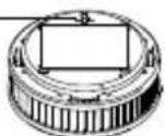
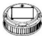
The smoke alarm unit is held in place by a magnetic holder attached to the mounting site. Please note that the magnetic holder only has a strong attractive force from one direction. The magnetic holder may be mounted either by an adhesive fixing or by drilled holes:
1. Adhesive Mounting


1.1 Adhesive mounting of magnetic carrier, self-adhesive coated in accordance with EN14604:2005/ AC:2008
The sole use of this self-adhesive fastener produces a
very maintenance-friendly
firm
- magnetic connection of the device to the installation site.
- The alarm unit can be removed by gently pulling downwards from the magnetic holder e.g. for inspection, maintenance or cleaning. For this adhesive mounting, only the adhesive supplied may be used.
The mounting site must be
firm
dry
- free of dust, grease or loose paint, etc.
Application:
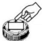
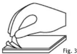
a) Remove the information sticker and the protective film from the self-adhesive surface (Fig. 3) of the magnetic holder.
b) Press the adhesive surface of the magnetic holder for approx. 10 seconds firmly onto the mounting surface.
c) Fit the alarm unit onto the magnetic holder.
d) The adhesive bond will reach its final strength after approx. 72 hours.
e) If required, the unit can be removed from the magnetic holder by pulling it gently vertically away
1.2 Adhesive mounting using optional fixing material (thin double-sided adhesive film) as per vfdb (German Fire Protection Association) 14/01 (Q) and EN14604:2005/AC:2008 in addition to 1.1
The additional use of this optional adhesive produces an
extremely firm
- and long-lasting joint between the alarm unit and the fixture and thus with the installation site.
- The alarm unit cannot now be removed by pulling it from the magnetic holder; this means significantly greater security against unauthorised removal, theft etc.
Only use this method of fixing when you are absolutely certain that the unit must remain permanently fixed and that it should not be removed.
Be certain to note that this is a very strong fixing; the unit can only be removed with great effort and possible damage to the mounting site and to the device. We accept no liability for any damage incurred.
For this adhesive mounting, only the adhesive supplied may be used.
The mounting site must be
firm
dry
- free of dust, grease or loose paint, etc.

Application:
a) Remove the information sticker and the protective film from the self-adhesive surface (Fig. 3) of the magnetic holder.
b) Press the adhesive surface of the magnetic holder for approx. 10 seconds firmly onto the mounting surface.
c) Remove the first protective film from the thin double-sided
adhesive film and press this firmly, smoothly and flush onto the entire metal surface of the smoke alarm unit.
d) Now remove the second protective film of the thin double-sided adhesive film and place the unit with gentle pressure onto the pre-mounted magnetic holder.
e) The adhesive bond will reach its final strength after approx. 72 hours.
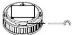
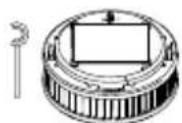
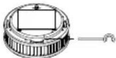
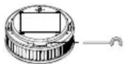
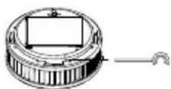
2. Drilled Hole Mounting Application:


a) Using an 8-mm drill bit, drill a hole at the installation position (take care not to strike any electric cables, etc. underneath).
b) Insert the 8-mm wall plug into the hole.
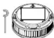
c) Push the 5-mm countersunk screw provided through the bottom of the magnetic holder and into the hole (Fig. 4).
d) Tighten the screw into the wall plug so that the screw sits flush and is fully sunk into the recess provided for it in the magnetic holder.
e) Only tighten the screw sufficiently to prevent the magnetic holder from deforming or bending.
f) Place the alarm unit on the magnetic holder.
g) If required the unit can be removed from the magnetic holder by pulling it gently vertically away.
Fig. 4
GENERAL SAFETY GUIDELINES
Smoke alarms are designed to help you detect fire at an early stage. They cannot, however, extinguish a fire nor prevent it starting, nor can they notify the fire brigade. When danger is detected by the presence of combustion gases, smoke alarms issue a loud audio alarm to inform you of the danger. Despite great care in manufacture, it is also possible that a fault may occur in a smoke alarm unit that prevents it from warning of a potential fire, or from doing so in good
time. The usual precautions in relation to fire, flammable materials and technical equipment must always be observed. Please do not expose the device to direct sunlight or extreme heat, because it could damage the built-in battery. This device is a closed system. Any attempt to open
the unit, by whatever means, not only invalidates any warranty but also results in the unit no longer being fit for its intended use or permitted for such use.
GB
Do not open the unit under any circumstances as doing so may result in personal injury. No change of battery is necessary and is excluded for technical reasons. You should protect the unit, particularly during renovation work but also in general, against moisture, cold, heat, particulate matter, from oil, nicotine and paint fumes and from decorating materials such as wall paint, adhesives and dirt of any kind. During renovation, construction or sanding works the smoke alarm should be removed from the magnetic holder
(by a gentle downward pull) and stored in a safe place. Do not forget to fit the unit back onto the magnetic holder (III) when the work is completed!
IMPORTANT NOTE:
Only when the unit is situated in its intended location, clean, undamaged and activated, can it perform its potentially life-saving function of warning against fire.
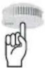
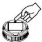
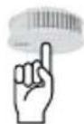
Trigger test tone
TESTING, MAINTENANCE AND SERVICING
This smoke alarm automatically tests its functional readiness once every minute. It automatically adjusts the sensitivity of its detection optics according to the prevailing
environmental conditions. If the energy reserves of the smoke alarm are depleted or the detection optics are so contaminated that it can no longer adjust its sensitivity to the conditions, the device indicates this situation at an early stage so that you have sufficient time to replace the smoke alarm with a new unit.
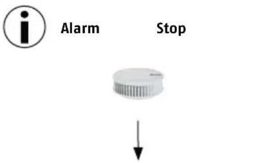
Stop: temporarily deactivate or silence alarm.
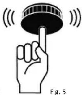
You should ensure that the air inlets around the sides of the smoke alarm never become constricted by dust, dirt, paint or adhesive tape, etc. To check that the device is fully functional you should regularly (at least once per month) test the alarm. To do this, press the Test and Stop button (Fig. 1, IV) to trigger a test
alarm (Fig. 5). When you do this, check that the unit is undamaged and securely fixed to its mounting location, and that the air inlet fins (Fig. 1, II) are completely free of foreign bodies.
To ensure the continued functional readiness of the alarm, the unit should be maintained as described in DIN 14676 at least once per year. To do this, proceed as follows:
- Dust the unit if necessary with a damp cloth; remove any contamination with a damp cloth. Do not use detergent.
The maximum service life and the intended service life of the device is not more than 12 years. These 12 years can be divided into a typical service life of 10 years plus a maximum further 2 years service life/energy reserve for the product. You should replace the unit after this period.
POSSIBLE CAUSES OF FALSE ALARMS
| False Alarms or Errors Possible Causes | |
| A device that is to be assigned to a radio group is no longer in connection mode | Connection mode is active for 10 minutes. To reactivate connection mode after this, see "Repeat Connection Attempts" |
| Devices of the radio group to which further alarms are to be assigned are not, or are no longer, in connection mode. | Connection mode is active for 10 minutes. To reactivate connection mode after this, see "Extending the Existing Radio Group/Re-entering Connection Mode" |
| The distance between two alarms in connection mode is too great; no connection is possible | Reduce distance between the alarms; to do so, add an extra alarm |
| One alarm will not connect to the radio group | Restore alarm to factory settings, see "Restore Factory Settings"; enter connection mode |
POSSIBLE CAUSES OF A FALSE ALARM
- Dust in the calibration system of the device
- More or less dust is normal in living rooms
- Particularly in bedrooms due to carpets, clothing, blankets, pillows etc.
and their storage and movement - Pollen, construction dust, abrasive dust and particulate matter
- Small insects
Prevention:
-
Regular and careful cleaning of the device
-
Very strong fumes from cooking, steaming and/or frying
Air freshener, fragrance sprays and insect sprays
Prevention:
Good ventilation of rooms
- Do not use sprays near the alarm
- Extreme temperature fluctuations or very strong electromagnetic radiation in the proximity of the alarm
Cigarette smoke
Only triggers alarm when in very high concentration or very close to unit
Prevention:
- Protect unit against the environmental factors listed
WARRANTY
- ABUS products are designed and manufactured with great care and tested in accordance with applicable regulations.
- The warranty extends solely to defects that can be attributed to faulty materials or manufacturing. If it is demonstrable that materials or manufacturing are faulty, the guarantor will repair or replace the smoke alarm at his own discretion.
Warranty in these cases ends with the expiry of the original warranty period of two years. Any further claims are expressly excluded.
-
ABUS accepts no liability for defects or damage arising from external influences (e.g. transport, forceful impact, incorrect operation), improper use, ordinary wear and tear or the non-observation of this manual.
-
When making a warranty claim, the faulty smoke alarm should be accompanied by the original proof of purchase with purchase date and a short written description of the fault.
If you discover a fault in the smoke alarm that was present at the time of sale, please contact your dealer within the first two years.
INTENDED USE
This device is intended solely for smoke detection and warning of heat in occupied properties and for forwarding alarms from other units. Any other use that is not expressly stated in this user manual as permissible, is deemed as not in conformity with intended use. This device may only be used for the following purpose(s):
- Fire or smoke detection in private households and occupied properties, including forwarding alarms via radio interlink.
The device has been tested for use in recreational camping vehicles (e. g. camper vans).
- This radio-interlinked smoke alarm features a heat warning function. It is not, however, a heat detector as defined in EN 54-5.
- This radio-interlinked smoke alarm can be connected to radio groups or common radio groups that issue the alarm of one radio-interline smoke alarm as a group alarm through radio forwarding of the alarm. It is not, however, a wireless smoke alarm as defined in EN 54-25.
DECLARATION OF CONFORMITY
ABUS August Bremicker Söhne KG, Altenhofer Weg 25, 58300 Wetter, hereby declares that the RWM450 complies with the basic requirements and other relevant terms of the 1999/5/EG. For further information on the CE declaration or to view the CE
declaration, please get in touch with ABUS August Bremicker Sohne KG, Kundenservicecenter, Altenhofer Weg 25, 58300 Wetter.
DECLARATION OF PERFORMANCE 2015RWM450
This smoke detector has been tested and certified as a construction product in accordance with EU Regulation 305/2011. It has been manufactured subject to monitoring by regular and independent inspections for changes in compliance with legal and normative requirements.
The declaration of performance can be found at www.abus.com Please enter the smoke detector model (RWM450) in the search field at the top right and then go to
downloads. Double click to select the declaration of performance. In addition, you can also find here the data sheet and operating instructions for the smoke detector. EN 14604:200 AC:2008

EN 14604:2005/ AC:2008 C€ 15 1772-CPR-150087
LIABILITY DISCLAIMER
ABUS, AUGUST BREMICKER SOHNE KG (HEREINFTER REFERRED TO AS ABUS) ACCEPTS NO FURTHER LIABILITY, EXPLICIT OR IMPLICIT, WITHIN THE FRAMEWORK OF EXISTING LEGISLATION. THIS EXTENDS TO ANY LIABILITY IN RESPECT OF USE-ABILITY AND/OR SUITABILITY FOR PARTICULAR PURPOSES IN THE CONTEXT OF IMPLICIT LIABILITY THAT NEVERLESS CONSISTS OF LEGAL REGULATIONS; THE WARRANTY ARE LIMITED TO THE DURATION OF THESE WARRANTYES.
LIMITATION OF LIABILITY
YOUR RIGHTS ARE LIMITED TO THE REPAIR OR REPLACEMENT OF THIS PRODUCT IN CONDITION AS DELIVERED. ABUS ACCEPTS NO LIABILITY FOR ANY SPECIAL, INCIDENTALLY ARISING OR CONSEQUENTAL DAMAGE, INCLUDING, BUT NOT LIMITED TO, LOSS OF REVENUE, LOSS OF PROFIT, RESTRICTIONS IN USE OF THE SOFTWARE, LOSS OR RECOVERY OF DATA, COSTS FOR REPLACEMENT FACILITIES, DOWN TIMES, DAMAGE TO PROPERTY
AND CLAIMS BY THIRD PARTIES, INCLUDING THOSE ARISING FROM CONTRACTUAL OR LEGAL CLAIMS FOR RECOVERY OR THOSE ARISING IN THE LAW OF DAMAGES, NOTWITHSTANDING OTHER RESTRICTED OR LEGALLY IMPLICIT WARRANTY PROVISIONS OR IN CASES WHERE THE LIMITED WARRANTY IS NOT VALID, THE SCOPE OF LIABILITY OF ABUS IS LIMITED TO THE PURCHASE PRICE OF THE PRODUCT.
CONFORMS TO R&TTE
ABUS August Bremicker Söhne KG hereby declares that the RWM450 is in compliance with the essential requirements and the other applicable provisions of the 1999/5/EC Directive. The Declaration of Conformity can be downloaded from the following address: www.abus.com
CONFORMITY TO vfdb (German Fire Protection Association)14/01 (Q)
This product is certified to vfdb guidelines (Q)
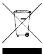
DISPOSAL
In accordance with the WEEE Directive 2002/96/EC, this product must not be disposed of in household waste. Please return the unit to the manufacturer for further recycling or pass it to your regional waste management company. Please note that improper disposal may result in harm to the environment.
What to do if there is a fire?
—ert all cohabitants.
Help all children, disabled, elderly and sick people.
Close all windows and doors behind you.
leave the building immediately.
not use the elevators.
Alert the fire service: Telephone 112

ABUS
Warning! Small parts may be swallowed by children!
^© ABUS | D 58292 Wetter | Germany | www.abus.com

RWM450
Security Tech Germany
CAUSES POSSIBLES DE FAUSSES ALARMES
ALARM EN WAARSCHUWINGS-SIGNALEN 102
LICHTSIGNALEN VAN DE LED 104
KEUZELOCATIE 105
INGEBRUIKNAME EN KOPPELING
INGEBRUIKNAME 106
KOPPELING 108
MONTAGE 119
LIJMEN 119
·BOREN 121
ALGEMENE VEILIGHEIDSVOORSCHRIFTEN 121

CONFORMITEI conf. VFDB 14/01129
VERWIJDERING
130
HARTELIJK DANK!
ALARM- EN WAARSCHUWINGSSIGNALEN
Alarmsignalen:
Security Tech Germany

- DANKE!
- HAFTUNGSAUSSCHLUSS
- CONTENTS
- THANK YOU!
- METHOD OF FUNCTIONING
- ALARM AND INDICATION SOUNDS
- Indication sounds:
- Volume:
- Alarm sounds:
- Silencing the alarm sounds
- Cause:
- Silencing the indication sounds:
- Damage to the device invalidates the warranty and guarantee
- LED:
- SETTING UP AND ESTABLISHING THE NETWORK
- Setting Up
- Activation and setup of radio groups:
- Do not network alarms that are less than 1 m apart - signal overlap - faults in network setup
- Setting Up the "Master":
- Network setup
- Setting up other RISAs; Connection Mode and creating a Radio Group
- For this see section: Setting up other RISAs; Connection Mode and Creating a Radio Group
- If LED then lights red:
- If this occurs please check:
- Completing Setup of Radio Group
- Radio Group Function Test
- Beep
- 1x
- 1
- Repeat Connection Attempts
- Extending the Existing Radio Group/ Re-entering Connection Mode
- LED
- seconds
- Please note:
- dnn pnnn
- Example:
- Forwarding Alarm Outside Radio Range
- MOUNTING
- Adhesive Mounting
- The mounting site must be
- Application:
- Drilled Hole Mounting Application:
- GENERAL SAFETY GUIDELINES
- IMPORTANT NOTE:
- TESTING, MAINTENANCE AND SERVICING
- POSSIBLE CAUSES OF FALSE ALARMS
- POSSIBLE CAUSES OF A FALSE ALARM
- Prevention:
- WARRANTY
- INTENDED USE
- DECLARATION OF CONFORMITY
- CONFORMS TO R&TTE
- DISPOSAL
- What to do if there is a fire?
- ABUS
- RWM450
- CAUSES POSSIBLES DE FAUSSES ALARMES
- HARTELIJK DANK!
- ALARM- EN WAARSCHUWINGSSIGNALEN
- Alarmsignalen:
Brand : ABUS
Model : RWM450
Category : Smoke detector