111850 - Thermostat Xavax - Free user manual and instructions
Find the device manual for free 111850 Xavax in PDF.
User questions about 111850 Xavax
0 question about this device. Answer the ones you know or ask your own.
Ask a new question about this device
Download the instructions for your Thermostat in PDF format for free! Find your manual 111850 - Xavax and take your electronic device back in hand. On this page are published all the documents necessary for the use of your device. 111850 by Xavax.
USER MANUAL 111850 Xavax
Energy-saving controller for radiators (p. 18)
I. Operation and Display 19
II. General function 20
Step 1: Inserting (replacing) the batteries. 20
Step 2: Setting the date and time of day 21
Step 3: Installing the energy-saving controller. 22
1. Setting the weekly program 23
2. Weekly program: Examples 24
3. Operating modes 25
4. Configuration menu.. 25
5. Display content during normal operation.. 26
6. Setting the holiday function 26
7 Comfort and set-back temperatures. 27
8. Child-proof lock/Operating inhibit. 27
9. Setting the heating break 28
10. Setting frost protection mode 28
11. Window open" function 28
12. Setting the offset temperature 29
13. Restoring the factory settings 29
14. Intended use 30
15. Troubleshooting and maintenance.. 30
16. Instructions for disposal 31
17. Safety instructions 31
18. Adapter overview 32
19. Technical properties 33
Please read this manual carefully in order to help you put the device into operation. Keep the manual handy so you can refer to it at a later date!
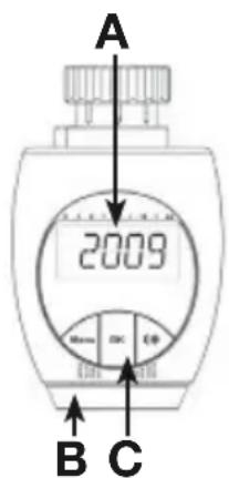
I. Operation and display
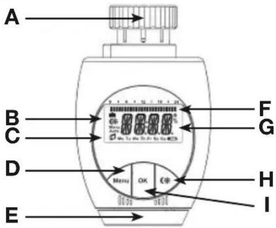
A Thermal ring
B Holiday function ( ) , set-back/comfort temperature ( ), manual operation (Manu), automatic operation (Auto)
C "Window open" symbol (D), day of the week, "battery empty" symbol (E)
D Menu button: Press and hold down the button for more than 3 seconds to open the configuration menu
E Setting wheel: Formaking adjustments (e.g. temperature)
F Switching periods set within weekly program
G Current temperature setting, time and date indicator, menu items, functions
H button: For switching between set-back and comfort temperatures
OK button: For confirming/saving
II. General function
This energy-saving controller for radiators can be used to control room temperature on the basis of time. The actuator moves a valve, thereby allowing the amount of heat flowing to the heating appliance to be controlled. The controller is compatible with all standard heating appliance valves.
Installation can be achieved in 3 easy steps.
Step 1: Inserting (replacing) the batteries
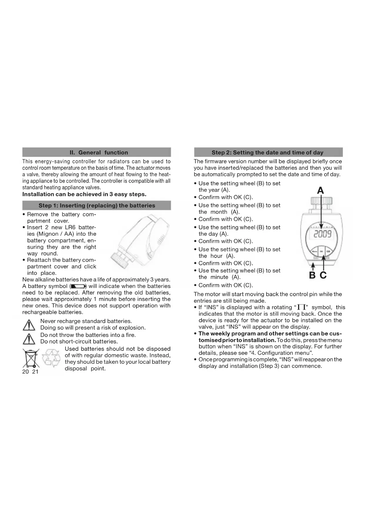
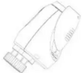
- Remove the battery compartment cover.
- Insert 2 new LR6 batteries (Mignon / AA) into the battery compartment, ensuring they are the right way round.
- Reattach the battery compartment cover and click into place.
New alkaline batteries have a life of approximately 3 years. A battery symbol ( ) will indicate when the batteries need to be replaced. After removing the old batteries, please wait approximately 1 minute before inserting the new ones. This device does not support operation with rechargeable batteries.

Never recharge standard batteries.

Doing so will present a risk of explosion.
Do not throw the batteries into a fire.
Do not short-circuit batteries.
Used batteries should not be disposed of with regular domestic waste. Instead, they should be taken to your local battery disposal point.
Step 2: Setting the date and time of day
The firmware version number will be displayed briefly once you have inserted/replaced the batteries and then you will be automatically prompted to set the date and time of day.
- Use the setting wheel (B) to set the year (A).
- Confirm with OK (C).
- Use the setting wheel (B) to set the month (A).
- Confirm with OK (C).
- Use the setting wheel (B) to set the day (A).
- Confirm with OK (C).
- Use the setting wheel (B) to set the hour (A).
- Confirm with OK (C).
- Use the setting wheel (B) to set the minute (A).
- Confirm with OK (C).
The motor will start moving back the control pin while the entries are still being made.
- If "INS" is displayed with a rotating "Π" symbol, this indicates that the motor is still moving back. Once the device is ready for the actuator to be installed on the valve, just "INS" will appear on the display.
- The weekly program and other settings can be customised prior to installation. To do this, press the menu button when "INS" is shown on the display. For further details, please see "4. Configuration menu".
- Once programming is complete, "INS" will reappear on the display and installation (Step 3) can commence.
Step 3: Installing the energy-saving controller
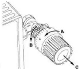
The actuator can be installed on all standard heating valves. There is no need to drain away water or fiddle around with the heating system before doing this. First, you need to remove the old thermostat dial:
- Turn the thermostat dial anticlockwise as far as it will go (A).
- Release the thermal ring of the thermostat (B).
- Remove the thermostat from the valve (C).
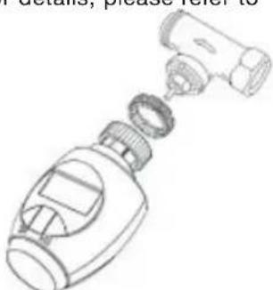
An adapter will need to be used in the case of certain valves.
Adapters for Danfoss valves (RA, RAV, RAVL) are included in the scope of delivery. For details, please refer to the adapter overview (see 18).
- The adapter must be placed on the valve and turned until it is securely seated.
- In the case of the RAV adapter, the extension supplied must be attached to the valve tappet.
- The RA and RAV adapters must, in addition, be secured by means of the bolt and nut supplied.
The energy-saving controller can only be installed if "INS" is showing on the display. Following installation, the actuator will perform an adjustment run so that it can adapt to the valve. During this process, "ADA" will be displayed.
- Place the actuator on the valve.
- Tighten the union nut.
22 23
- "INS" will appear on the display, press the OK button.
- The actuator will perform an adjustment run ("ADA" will appear on the display, operation not possible).
After that, the actuator will be ready for operation (Auto mode).
If the adjustment run was initiated prior to installation, or if an error message will be displayed (F1, F2, F3); press OK to move the motor back to the "INS" position.
1. Setting the weekly program
The weekly program allows you to set up to 3 separate heating periods (7 switching times) for each day of the week. Programming is performed in relation to the selected days, for which temperatures must be stored for a period from 00:00 to 23:59.
Press and hold down the menu button for more than 3 seconds.
- "PRO" will appear on the display.
- Confirm with OK.
-
"DAY" will appear on the display. The setting wheel can be used to select an individual day of the week, all working days, the weekend or the entire week (example shows working days selected).
-
Confirm with OK.
-
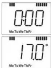
The first setting time will appear on the display (0:00). This cannot be changed. In addition, the display shows bars for every other switching interval.
- Confirm with OK.
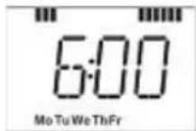
- Set the temperature that is to be maintained from 0:00 onwards (example shows 17.0^ ).
- Confirm with OK.
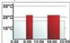
- The next switching time appears on the display (example shows 6:00). Use the setting wheel to set the time.
- Confirm with OK.
- Then, select a temperature for the selected switching time.
- Keep repeating this process until you have finished storing temperatures for the period from 0:00 to 23:59.
After all 7 switching times have been selected, 23:59 will appear on the display as end time. - Confirm with OK.
In Auto mode, the temperature can be modified at any time via the setting wheel. The modified temperature will then be retained until the next program changeover.
2. Weekly program: Examples
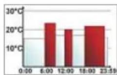
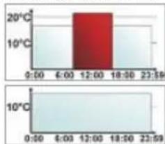
The energy-saving controller allows you to store up to 3 heating periods (7 switching times) with individual temperature settings for each day of the week. The factory setting consists of two heating phases (from 6:00 until 9:00 and from 17:00 until 23:00 respectively) for every single day of the week:
From 00:00 to 06:00 17.0^
From 06:00 to 09:00 21.0°C
From 09:00 to 17:00 17.0^
From 17:00 to 23:00 21.0°C
From 23:00 to 23:59 17.0^
To represent the switching periods, the display shows bars for every other switching interval. In this example, no bars are shown for the interval from 0:00 to 6:00. Bars are only shown on the display for the intervals from 6:00 to 9:00 and from 17:00 to 23:00.
If a room also needs to be heated at around noon, the corresponding program might look like this:
Monday to Sunday
From 00:00 to 06:00 16.0°C
From 06:00 to 09:00 22.0°C
From 09:00 to 12:00 17.0°C
From 12:00 to 14:00 20.0°C
From 14:00 to 17:30 17.0°C
From 17:30 to 23:30 21.0°C
From 23:30 to 23:59 16.0°C
If you have a home office and only want it to be heated during the day on working days, you can program the fol
lowing times:
Monday to Friday
From 00:00 to 08:30 17.0°C
From 08:30 to 17:00 21.0°C
From 17:00 to 23:59 17.0°C
Saturday and Sunday
From 00:00 to 23:59 15.0°C
3. Operating modes
To switch between the 3 operating modes described below, press the menu button briefly (these operating modes can only be selected following installation/Step 3):
- Holiday function ( : Set a temperature that is to be maintained until a fixed point in time.
- Manu: Manual operation - The temperature is set manually using the setting wheel.
- Auto: Weekly program - The temperature is controlled automatically in accordance with the stored weekly program.
4. Configuration menu
The configuration menu can be used to modify settings. To access this menu, press and hold down the menu button (for more than 3 seconds).
PRO: For setting the weekly program (see Section "1 Setting the weekly program")
- DAT: For modifying the time of day and date
- POS: For querying the actuator's current position
- DST: Automatic switchover at the start or end of daylight saving time can be deactivated.
- AER: For setting the "window open" temperature and time so that the temperature is automatically reduced in the event of ventilation
- TOF: For setting the offset temperature
RES: For restoring the factory settings
Use the setting wheel to select menu items and the OK button to confirm your choice. Press the menu button again to return to the previous level. After 65 seconds without anything happening, the menu will close automatically.
5. Display content during normal operation
During normal operation, the following are displayed: switching periods, operating mode, temperature setting and day of the week.
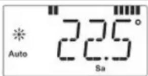
The bars indicating the week
ly program's switching periods are shown for every other time interval. For an example, please refer to "2. Weekly program: Examples".
6. Setting the holiday function
If you want a fixed temperature to be maintained for a set period of time while you are on holiday or during a party, you can make use of the Holiday function.
- Press and release the menu button repeatedly until the suitcase symbol ) appears on the display.
- Use the setting wheel to set the end of the time period during which the temperature is to be maintained.
- Press the OK button to confirm.
- Then use the setting wheel to set the date.
- Press the OK button to confirm.
- Use the setting wheel to set the temperature; press OK to confirm. The display will flash to confirm your settings. The set temperature will remain in force until the specified time. After that, the actuator will adopt Auto mode.
7. Comfort and set-back temperatures
The comfort/set-back temperature button (CK) provides an easy and convenient way of switching between these two temperatures. The factory settings are 21.0^ and 17.0^ respectively. To adapt them, proceed as follows:
- Press and hold down the comfort/set-back temperature button (OK) for more than 3 seconds.
- The sun symbol () will appear on the display along with the current comfort temperature.
- Use the setting wheel to modify the temperature; press OK to confirm.
- The moon symbol (C) will appear together with the setback temperature.
- Use the setting wheel to modify the temperature; press OK to confirm.
The temperature can even be modified in Auto mode at any time by using this button. The new setting will be retained until the program's next switching time.
8. Child-proof lock/Operating inhibit
Operation can be inhibited.
- To activate/deactivate the operating inhibit, briefly press the Menu and * buttons at the same time.
- Once the function is active, "LOC" will appear on the display.
- To deactivate the function, press both buttons again.
9. Setting the heating break
If the heating is being switched off for the summer, you can save battery power. This involves opening the valve up fully. Limescale protection measures remain in place.
- To activate the heating break, turn the setting wheel clockwise during manual operation (Manu) until "ON" appears on the display.
- To terminate the heating break, quit manual operation (Manu) or turn the setting wheel anticlockwise.
10. Setting frost protection mode
If you do not want the room to be heated, the valve can be closed. It will only be opened again if there is a risk of freezing due to frost. Limescale protection measures remain in place.
- To activate frost protection mode, turn the setting wheel anticlockwise during manual operation (Manu) until "OFF" appears on the display.
- To terminate frost protection mode, quit manual operation (Manu) or turn the setting wheel clockwise.
11. "Window open" function
In the event of a significant drop in temperature, the actuator can automatically detect whether the room is being ventilated. To save on heating costs, the temperature is then automatically reduced for a specific time period (factory setting: 15 minutes). While this function is active, the "window open" symbol () appears on the display.
- Press and hold down the menu button for more than 3 seconds.
- Use the setting wheel to select the "AER" menu item.
- Confirm with OK.
- Use the setting wheel to set the temperature and time. To deactivate the function, select a time of "0".
12. Setting the offset temperature
The temperature is measured at the heating appliance itself, with the result that other parts of the room may be warmer or colder than this. To allow for this, you can set a temperature offset of ± 3.5^ . If, for example, a temperature of 18^ is measured somewhere within the room instead of the 20^ set, it means that an offset of -2.0^ needs to be configured.
- Press and hold down the menu button for more than 3 seconds.
- Use the setting wheel to select the "TOF" menu item.
- Confirm with OK.
- Use the setting wheel to modify the temperature.
- Press the OK button to confirm.
13. Restoring the factory settings
You can reset the actuator to its initial state manually. This will clear all the settings that have been made manually.
- Press and hold down the menu button for more than 3 seconds.
- Use the setting wheel to select the "RES" menu item.
- Confirm with OK.
- "CFM" will appear on the display; press OK to confirm.
14. Intended use
The energy-saving controller has been designed for the purpose of controlling a standard heating appliance valve. The device may only be operated indoors and must be protected from the effects of damp and dust, as well as solar radiation and sources of radiant heat. Using the device for a purpose or in a manner other than that described in this operating manual constitutes a breach of the "intended use" and shall invalidate the warranty and any liability claims. The same shall apply in the event of any conversion or modification work. The devices are intended exclusively for domestic use.
- Troubleshooting and maintenance
| Error code on display | Problem | R emedy |
| Battery symbol | Battery power too low | Replace batteries |
| F1 | Valve actuator sluggish | Check installation, inspect heating valve |
| F2 | Adjusting range too large | Check actuator fastening |
| F3 | Adjusting range too small | Check heating valve |

At 12:00 every Saturday, the actuator performs a weekly descaling function to prevent valve calcification. "CAL" will appear on the display.
16. Instructions for disposal
Do not dispose of the device with regular domestic waste.
Electronic equipment must be disposed of at local collection points for waste electronic equipment in compliance with local directives governing electrical and electronic equipment.
waste

The CE sign is a free trade sign addressed exclusively to the authorities and does not warrant any properties.
17. Safety instructions
The devices concerned are not intended for children and must not be used as toys. Do not leave packaging material lying around, as children might be tempted to play with it, which is extremely dangerous. Do not open the device: it does not contain any components that need to be serviced by the user. In the event of an error, please return the device to our service department.
- Adapter overview
| Manufacturer | Figure | Adapter |
| Heimeier, MNG, Jun-kers, Landis&Gyr “Duodyr”, Honeywell-Braukmann, Oventrop, Schlösser, Simplex, Valf Sanayii, Mertik Maxitrol, Watts, Wingenroth (Wiroflex), R.B.M., Tiemme, Jaga | No adapter required | |
| Danfoss RA | Included in scope of supply | |
| Danfoss RAV | Included in scope of supply | |
| Danfoss RAVL | Included in scope of supply |
Other adapters available as accessories.
- Technical properties
| Supply voltage: 3 V | |
| Max. current consumption: | 100 mA |
| Batteries: | 2x LR6 / Mignon / AA |
| Battery life: | Approx. 3 years |
| Display: | LC display |
| Housing dimensions: | 63 x 66 x 92 mm (W x H x D) |
| Connection: M30 x 1.5 | |
We reserve the right to make any technical changes that constitute an improvement to the device.
Table des matieres
Distributed by Hama GmbH & Co KG
D-86652 Monheim
+49 9091 502-0
www.xavax.eu