VPA2200MBN - Receiver HQ Power - Free user manual and instructions
Find the device manual for free VPA2200MBN HQ Power in PDF.

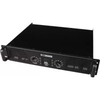
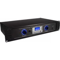
| Product type | Stereo power amplifier |
| Brand | HQ Power |
| Model | VPA2200MBN |
| Power supply | 230 VAC / 50 Hz |
| Stereo output power | 2 x 200 W RMS into 4 Ω, 2 x 100 W RMS into 8 Ω |
| Mono/bridged output power | 300 W RMS into 8 Ω |
| Total harmonic distortion | < 0.04 % |
| Frequency response | 10 Hz ~ 40 kHz / 8 Ω (at 10 V RMS) |
| Damping factor | > 200 / 8 Ω |
| Slew rate | > 30 V/μs |
| Signal-to-noise ratio | > 110 dB |
| Input sensitivity | 1.23 V RMS (±1 dB) |
| Minimum load impedance | 4 Ω per channel in stereo, 8 Ω in bridged mode |
| Inputs | 2 x XLR (female) and 2 x 6.35 mm jack (mono) for channels A and B |
| Speaker outputs | Speakon NL-4FC connectors (channels A, B and bridge output) |
| LED indicators | Power, Signal, Clip, Protect |
| Fuse | F 5 A, 250 VAC (5 x 20 mm) - reference FF5N |
| Cooling | Automatic (forced ventilation) |
| Dimensions | 482 x 310 x 95 mm |
| Weight | 13 kg |
| Max. ambient temperature | 45 °C |
| Intended use | Indoor only, professional or consumer use |
| Maintenance and cleaning | Wipe with a damp lint-free cloth; do not use alcohol or solvents. Disconnect before cleaning. |
| Spare parts and repairability | User-replaceable fuse. Other repairs by a qualified technician. Contact the dealer for spare parts. |
| Safety | Protection class I (mandatory grounding). Do not expose to rain or humidity. Disconnect before opening. Use only with a grounded outlet. |
Frequently Asked Questions - VPA2200MBN HQ Power
User questions about VPA2200MBN HQ Power
0 question about this device. Answer the ones you know or ask your own.
Ask a new question about this device
Download the instructions for your Receiver in PDF format for free! Find your manual VPA2200MBN - HQ Power and take your electronic device back in hand. On this page are published all the documents necessary for the use of your device. VPA2200MBN by HQ Power.
USER MANUAL VPA2200MBN HQ Power
To all residents of the European Union
Important environmental information about this product
This symbol on the device or the package indicates that disposal of the device after its lifecycle could harm the environment.
Do not dispose of the unit (or batteries) as unsorted municipal waste; it should be taken to a specialised company for recycling.
This device should be returned to your distributor or to a local recycling service.
Respect the local environmental rules.
If in doubt, contact your local waste disposal authorities.
Thank you for buying the VPA2200MBN! Please read the manual thoroughly before bringing this device into service. If the device was damaged in transit, don't install or use it and contact your dealer.
2. Safety Instructions

Be very careful during the installation: touching live wires can cause life-threatening electroshocks.

Keep this device away from rain and moisture.

Unplug the mains lead before opening the housing.
- Damage caused by disregard of certain guidelines in this manual is not covered by the warranty and the dealer will not accept responsibility for any ensuing defects or problems.
- A qualified technician should install and service this device.
- Do not switch the device on immediately after it has been exposed to changes in temperature. Protect the device against damage by leaving it switched off until it has reached room temperature.
- This device falls under protection class I. Plug the device into a mains with a protective earthing. Have a qualified person carry out the electric connection.
- Do not expose the device to dripping or splashing liquids. Never place objects filled with liquids, such as vases, on top of the device.
- Make sure that the available voltage does not exceed the voltage stated in the specifications of this manual.
- Do not crimp the power cord and protect it against damage. Have an authorised dealer replace it if necessary.
- Disconnect the device from the mains to clean it or when it is not in use. Handle the power cord by the plug only.
- Note that damage caused by user modifications to the device is not covered by the warranty.
- Keep the device away from children and unauthorised users.
3. General Guidelines
- The VPA2200MBN should only be used indoors connected to an alternating current of max. 230V AC/50Hz.
- Do not shake the device. Avoid brute force when installing or operating the device.
- Select a location where the device is protected against extreme heat ( >45^ ), direct sunlight, dust and moisture. Install it in a well-ventilated area and leave a distance of 30cm in front of and behind the device for ventilation.
- Make sure the cooling circulation is never obstructed. Clean the ventilation openings regularly.
- Keep the device away from dripping and splashing liquids. Never place any objects filled with liquids, such as vases, onto the device.
- Place the power switch of the device in the off position to completely disconnect the power.
- Familiarise yourself with the functions of the device before actually using it. Do not allow operation by unqualified people. Any damage that may occur will most probably be due to unprofessional use of the device.
- Use the original packaging if the device is to be transported.
- All modifications of the device are forbidden for safety reasons.
- Only use the device for its intended purpose. All other uses may lead to short circuits, burns, electroshocks, crash, etc. Using the device in an unauthorised way will void the warranty.
4. Fuse Replacement
- Only fit or replace a fuse when the device is unplugged from the mains.
-
Replace a blown fuse with a fuse of the same type and rating (250Vac / 5A 5 x 20mm fuse, order code FF5N):
-
Unscrew the fuse holder cap at the back with an appropriate screwdriver.
- Remove the old fuse and install a new one.
- Replace the old fuse holder and fasten it with the screwdriver.
5. Use
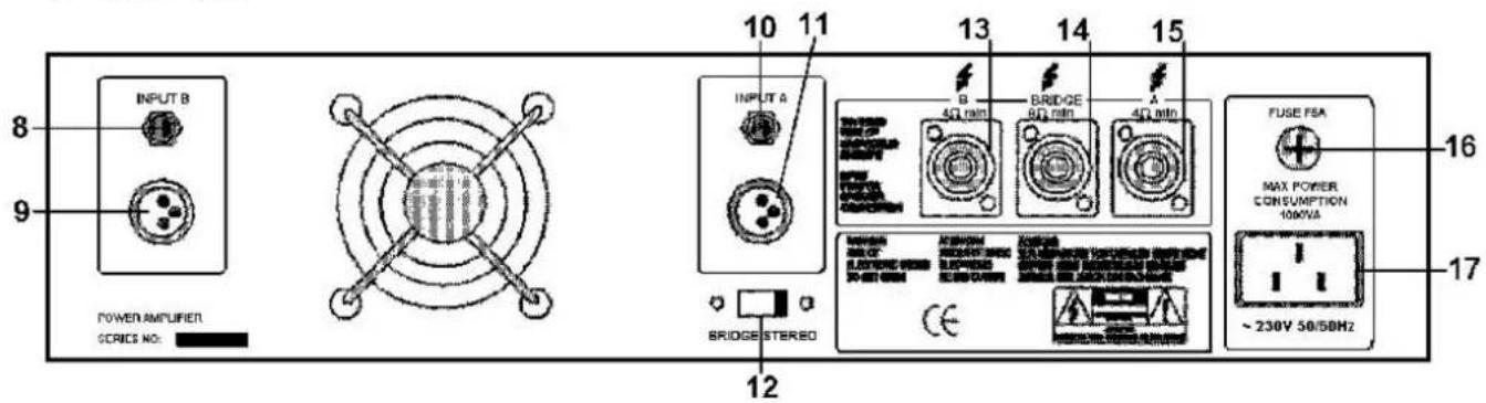
a. Front Panel
- ON/OFF switch
- CHANNEL A gain control. In MONO/BRIDGE use, it will control both channels simultaneously.
- CHANNEL B gain control
- ON/OFF LED ('POWER')
- PROTECTION LED ('PRO'): lights up when the amplifier gets too hot.
- SIGNAL LED ('SIGNAL'): this green LED indicates a safe operation (-30dB\~0dB).
- CLIPPING LED ('CLIP'): red LED indicates a state of over-modulation (distortion at high volumes). Check the input signal to the amplifier and turn down its level if possible. If not, turn down the gain control on the amplifier. Keep in mind that the amplifier cannot correct a distorted signal.
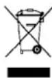
b. Back Panel
text_image
8 9 POWER AMPLIFIER SERIES NO: 10 11 INPUT A BRIDGE STEREO 12 13 14 15 B 4Ω min B RIDGE 8Ω min 4Ω min FUSE FSA MAX POWER CONSUMPTION 10MVA ~ 230V 30/50Hz 16 17- Channel B input through 6.35mm balanced mono jack.
- Channel B input through balanced XLR connector.
- Channel A input through 6.35mm balanced mono jack.
- Channel A input through balanced XLR jack.
- BRIDGE/STEREO selection switch.
- Channel B output (min. loudspeaker impedance: 4Ω).
- Bridge output: to be used when selector switch #12 is set to 'BRIDGE' (min. loudspeaker impedance: 8Ω).
- Channel A output (min. loudspeaker impedance: 4Ω).
- Fuse holder.
- Mains connector.
text_image
7 6 5 4 POWER PRO SIGNAL CLIP CLIP SIGNAL PRO POWER POWER PRO SIGNAL CLIP CHANNEL A CHANNEL B Professional Audio 2 1 3 10 9 8 7 6 5 4 CHANNEL A CHANNEL B Professional Audio .......... CHANNEL A CHANNEL Bc. Balanced / Unbalanced Input Connection

—1 screen
—2 hot
—3 cold
Both amplifier channels feature a balanced XLR female socket as well as a balanced 6.35 phone jack socket.
Input cables must be screened!
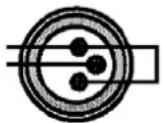
If an unbalanced input signal is to be connected using an XLR plug, a wire bridge must be inserted between PIN1 and PIN3 (see fig. on the left). For an unbalanced signal output, a 6.35mm mono jack plug can also be used.
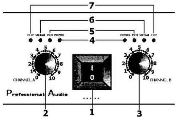
d. Mono / Bridge Mode
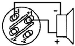
In MONO mode, only the channel A input is active. The selection switch (#12) must be set to the BRIDGE position. In BRIDGE mode, both amplifier channels (A & B) are internally bridged to perform as one single channel. Only the channel A input is active.
In both modes, only the BRIDGE output connector (#14) may be used. The channel A and B connectors (#13 & 15) are only for use in STEREO mode (selection switch #12 in STEREO position). The connection must be made as in the figure on the right, using a professional connector (type CAS101):
text_image
-1 +1 -2 +e. Stereo Mode
In STEREO mode, connect channels A and B through the XLR or phone jack plugs. The selector switch (#12) must be set to STEREO. Use the channel A & B output connectors (#13 & 15).
f. Parallel Mode
Mono or bridge mode will mostly only allow driving one single loudspeaker system due to the 8Ω min/ impedance. If, for example, a number of floor monitor loudspeaker systems (8Ω each) are to be driven, channels A and B should be operated in parallel mode:
- connect the input signal to the channel A XLR input
- connect the channel A and B phone jack inputs by means of a shielded patch cable
- set the selector switch (#12) to STEREO
- connect the speakers through connectors A and B (#12 & 15)
6. Cleaning and Maintenance
- All screws should be tightened and free of corrosion.
- The housing and fixations should not be deformed, modified or tampered.
- The electric power supply cables must not show any damage. Have a qualified technician maintain the device.
- Disconnect the device from the mains prior to maintenance activities.
- Wipe the device regularly with a moist, lint-free cloth. Do not use alcohol or solvents.
- There are no user-serviceable parts except for the fuse.
- Contact your dealer for spare parts if necessary.
7. Technical Specifications
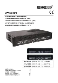
| Power Supply max. 230VAC/50Hz | |
| Power Output | 2 x 200Wrms/4Ω or 2 x 100Wrms/8Ω |
| Mono/bridged 300Wrms/8Ω | |
| Total harmonic distortion <0.04% | |
| Frequency response @ 10Vrms 10Hz ~ 40kHz/8Ω | |
| Damping factor >200/8Ω | |
| Slew rate >30V/μs | |
| S/N ratio >110dB | |
| Input sensitivity (±1dB) 1.23Vrms | |
| LED indication SIGNAL, CLIP, POWER, PROTECT | |
| Cooling control automatic | |
| Speaker connections SPEAKON NL-4FC | |
| Fuse F 5A, 250VAC (5 x 20mm) ( order code FF5N) | |
| Total Weight 13kg | |
| Dimensions 482 x 310 x 95mm | |
| Max. Ambient Temperature | 45°C |
The information in this manual is subject to change without prior notice.
VPA2200MBN - 2 X 200W RMS MOSFET VERMOGENVERSTERKER
text_image
-1 +1 -2 +2 -2 + -e. Stereo mode
text_image
-1 +1 +2 -2 + -e. Mode stéréo
text_image
-1 +1 +2 -2 + -e. Modo estéreo
text_image
-1 +1 -2 +2 -2 + -e. Stereo-Modus
Velleman® Service and Quality Warranty
Velleman® has over 35 years of experience in the electronics world and distributes its products in more than 85 countries.
All our products fulfil strict quality requirements and legal stipulations in the EU. In order to ensure the quality, our products regularly go through an extra quality check, both by an internal quality department and by specialized external organisations. If, all precautionary measures notwithstanding, problems should occur, please make appeal to our warranty (see guarantee conditions).
General Warranty Conditions Concerning Consumer Products (for EU):
- All consumer products are subject to a 24-month warranty on production flaws and defective material as from the original date of purchase.
- Velleman® can decide to replace an article with an equivalent article, or to refund the retail value totally or partially when the complaint is valid and a free repair or replacement of the article is impossible, or if the expenses are out of proportion.
You will be delivered a replacing article or a refund at the value of 100% of the purchase price in case of a flaw occurred in the first year after the date of purchase and delivery, or a replacing article at 50% of the purchase price or a refund at the value of 50% of the retail value in case of a flaw occurred in the second year after the date of purchase and delivery.
• Not covered by warranty:
- all direct or indirect damage caused after delivery to the article (e.g. by oxidation, shocks, falls, dust, dirt, humidity...), and by the article, as well as its contents (e.g. data loss), compensation for loss of profits;
- frequently replaced consumable goods, parts or accessories such as batteries, lamps, rubber parts, drive belts... (unlimited list);
- flaws resulting from fire, water damage, lightning, accident, natural disaster, etc. ...;
- flaws caused deliberately, negligently or resulting from improper handling, negligent maintenance, abusive use or use contrary to the manufacturer's instructions; - damage caused by a commercial, professional or collective use of the article (the warranty validity will be reduced to six (6) months when the article is used professionally);
- damage resulting from an inappropriate packing and shipping of the article;
- all damage caused by modification, repair or alteration performed by a third party without written permission by Velleman®.
- Articles to be repaired must be delivered to your Velleman® dealer, solidly packed (preferably in the original packaging), and be completed with the original receipt of purchase and a clear flaw description.
- Hint: In order to save on cost and time, please reread the manual and check if the flaw is caused by obvious causes prior to presenting the article for repair. Note that returning a non-defective article can also involve handling costs.
• Repairs occurring after warranty expiration are subject to shipping costs.
- The above conditions are without prejudice to all commercial warranties.