
GMD8500M - AV receiver PIONEER - Free user manual and instructions
Find the device manual for free GMD8500M PIONEER in PDF.
| Product Type | Monoblock Amplifier for Subwoofer |
| Brand | Pioneer |
| Model | GMD8500M |
| Dimensions (W × H × D) | 310 mm × 56 mm × 200 mm |
| Weight | 2.8 kg (wiring not included) |
| Supply Voltage | 14.4 V DC (10.8 V to 15.1 V acceptable) |
| Grounding | Negative pole |
| Power Consumption | 27 A (4 Ω continuous power supply) |
| Average Current Draw | 7.5 A (4 Ω for one channel) / 15 A (2 Ω for one channel) |
| Fuses | 30 A × 2 |
| Maximum Output Power | 600 W × 1 (4 Ω) / 1200 W × 1 (2 Ω) |
| Continuous Output Power | 300 W × 1 (14.4 V, 4 Ω, 20 Hz - 240 Hz, ≤1 % THD) / 600 W × 1 (14.4 V, 2 Ω, 50 Hz, ≤1 % THD) |
| Load Impedance | 4 Ω (2 Ω to 8 Ω acceptable) |
| Frequency Response | 10 Hz to 240 Hz (+0 dB, -3 dB) |
| Signal to Noise Ratio | 80 dB (IEC-A network) |
| Total Harmonic Distortion | 0.3 % (10 W, 100 Hz) |
| Low Pass Filter (LPF) | Cutoff Frequency: 40 Hz to 240 Hz, Slope: 12 dB/octave |
| Gain Adjustment | GAIN control (adjustable according to car stereo output level) |
| Bass Boost Level Remote | REMOTE jack connector (0 dB, 6 dB, 12 dB) |
| Input Selection | RCA (external output) or SP (speaker input with supplied cord) |
| Built-in Protection | Protection function against excessive outputs, temporary sound cutoff |
| Maintenance and Cleaning | Clean with a dry cloth; avoid contact with liquids |
| Safety | Use an identical fuse; connect ground properly; do not expose to moisture |
| Spare Parts and Repairability | Contact an authorized Pioneer service center |
Frequently Asked Questions - GMD8500M PIONEER
User questions about GMD8500M PIONEER
0 question about this device. Answer the ones you know or ask your own.
Ask a new question about this device
Download the instructions for your AV receiver in PDF format for free! Find your manual GMD8500M - PIONEER and take your electronic device back in hand. On this page are published all the documents necessary for the use of your device. GMD8500M by PIONEER.
USER MANUAL GMD8500M PIONEER
CLASS D MONO AMPLIFIER
AMPLIFICATEUR MONO DE CLASSE D
AMPLIFICATORE MONOFONICO DI CLASSE D
AMPLIFICADOR MONO CLASE D
PykoBODCTBO NOIb3OBaTeJIa
ThankyouforpurchasingthisPIONEERproduct.
Toensureproperuse,pleasereadthroughthismanualbeforeusingthisproduct.
Please keep the manualina safe and accessible place for future reference.

Beforeyoustart
Incaseoftrouble3
AboutThisProduct3
Beforeconnecting/installingtheamplifier3

SettingtheUnit
What'swhat5
Settinggainproperly5

Connectingtheunits
Connectiondiagram7
Beforeconnectingtheamplifier7
Connectingthespeakers8
Connectionswhenusingthespeakerinput wire8
Connectinghepowerterminal9
Connectingthespeakeroutput terminals10

Installation
Beforeinstallingtheamplifier11
AttachingtheBassboostremotecontrol11
Exampleofinstallationonthefloormator chassis11

Additionalinformation
Specifications13
Beforeyoustart

Ifyouwanttodisposethisproduct,donotmix itwithgeneralhouseholdwaste.Thereiseaseparatecollectionsystemforusedelectronic productsinaccordancewithlegislationthatrequirespropertreatment,recoveryandrecyclng.
Privatehouseholdsinthememberstates of theEU,inSwitzerlandandNorwaymayreturn theirusedelectronicproductsfreeofcharge todesignatedcollectionfacilitiesortoaretailer(ifyoupurchaseasimilarnewone).
For countriesnotmentionedabove,please contactyourlocalauthoritiesforthecorrect methodofdisposal.
Bydoingsoyouwillensurethatyourdispersed productundergoesthenecesssarytreatment, recoveryandrecyclingandthuspreventpotentialnegativeeffectsontheenvironment andhumanhealth.
Incaseoftrouble
Shouldthisproductfailtooperateproperly, pleasecontactyourdealerornearestauthorizedPioneerServiceStation.
AboutThisProduct
Thisproductisamonoamplifierforsubwoofer.lf bothL(left)andR(right)channelsareconnected totheRCAinputofthisproduct,outputismixed becausethisproductisamonoamplifier.
Beforeconnecting/ installingtheamplifier
WARNING
Theuseofaspecialredbatteryandground wireRD-223,availableseparately,isrecommended.Connectthebatterywiredirectlyto thecarbatterypositiveterminal ④ andthe groundwiretothecarbody.
- Thisunitisforvehicleswitha12Vbattery and negativegrounding.Beforeinstallinginrecreationalvehicles,trucksorbuses,checkthe batteryvoltage.
Theblackcableisground.Wheninstalling thisunit,makesuretoconnecttheground wirefirst.Ensurethatthegroundwireisproperlyconnectedtometalpartsofthecar's body.Thegroundwireoftheoneofthisunit mustbeconnectedtothecarseparatelywith differentscrews.lfhrescrewfortheground wireloosensorfallsout,itcouldresultinfire, generationofsmokeormalfunction.
- Useafuseoftheratingprescribed.
- Check the connection of the powersupply and speakers if the use of these separately sold batterywire or the amplifier fuses. Determine and resolve the cause, then replace the fuse with identical equivalent.
- Alwaysinstalltheamplifieronaflatsurface. Donotinstalltheamplifieronasurfacethat isnotflatoronasurfacewithaprotrusion. Doingsocouldresultimalfunction.
- Wheninstallingtheamplifier, donotallow partssuchasextrascrewstogetcaughtbetweentheamplifierandtheautomobile. Doingsocouldcausemalfunction.
- Donotallowthisunittocomeintocontact withliquids. Electricalshockcouldresult. Also,damagetothisunit,smoke,andoverheatingcouldresultfromcontactwithliquids. Thesurfacesoftheamplifierandanyattached speakersmayalsoheatupandcauseminor burns.
Beforeyoustart
- Intheeventofanyabnormality, the power supplytotheamplifieriscutofftoprevent equipmentmalfunction. Ifthisoccurs, switch thesystempowerOFFandcheckthepower supplyandspeakerconnections. Ifyouareunabletodeterminethecause, pleasecontact yourdealer.
- Disconnectthenegativeterminalofthebatterybeforeinstallation.

CAUTION
- Alwayskeep the volume lowened to hear outside sounds.
- Extendeduseofthecarstereowhiletheengineisatrestoridlingmayexhaustthebattery.
- Connecteithertoftwosubwooferstotheamplifier;1:asubwooferwitha350Worlargernominalinputandanimpedance4Ω, or 2 : asubwooferwitha600Worlargernominalinputandanimpedance2Ω.Ifthenominalinputandimpedanceareoutoftheaboveranges,thesubwoofermaycatchfire,emitsmokeorbecomedamaged.
SettingtheUnit
What'swhat
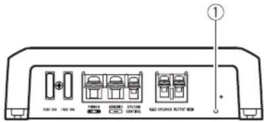
Frontside
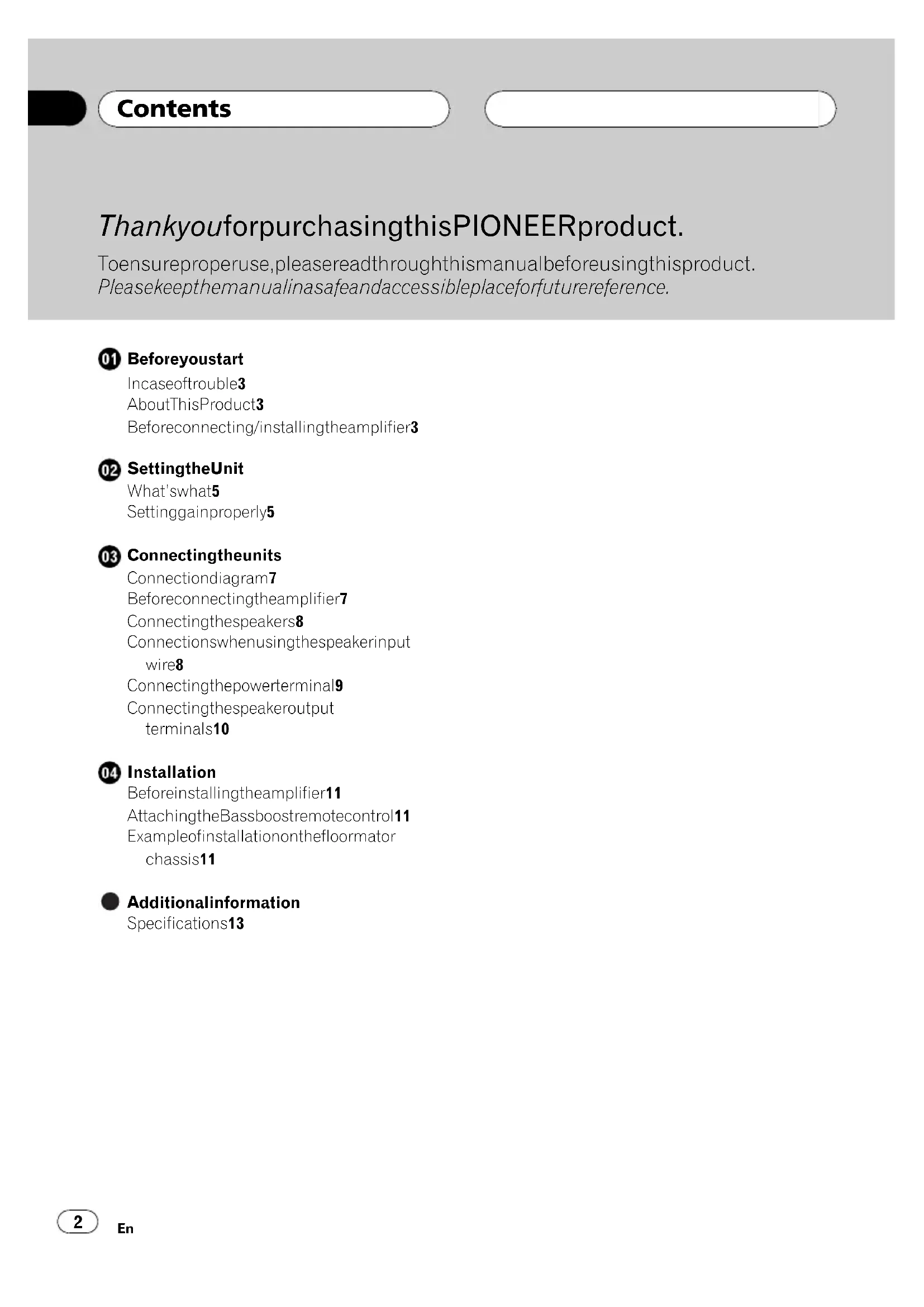
Rearside
Toadjusttheswitch,useaflatheadscrewdriverifneeded.
①Powerindicator
Thepowerindicatorlightsuptoindicate powerON.
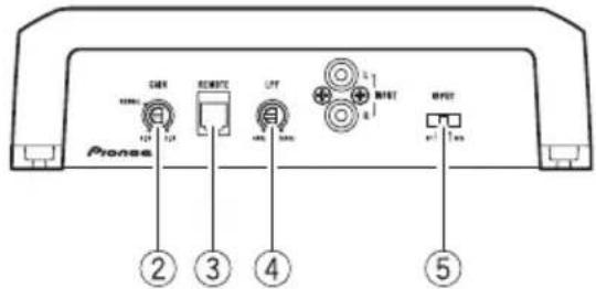
② GAIN(gain)control
Ifoutputremainslow,evenwhenthecar stereovolumeisturnedup,turncontrolsto lowerlevel. Ifdistortionoccurswhenthecar stereovolumeisturnedup, turnthesecontrolstohigherlevel.
-
ForusewithanRCAequippedcarstereo (standardoutputof500mV),settothe NORMALposition.ForcewithanRCA equippedPioneercarstereo,withmax. outputof4Vormore,adjustlevelto matchthatofthecarstereooutput.
-
Ifyouheartoomuchnoisewhenusing thespeakerinputterminals,turnthe gaincontroltoligherlevel.
③REMOTE(bassboostlevelremotecontrol)jack
ByconnectingtheBassboostlevelremote controltothejackonthemainunit,youwill
beabletoselectabassboostlevelfrom0 dB,6dBand12dB. Forinstructionofconnectingthebassboost remotecontroltotheamplifier,seetheConnectiondiagramonpage7.
LPF(low-passfilter)cutofffrequency control
Youcanselectacutoffrequencyfrom40 Hzto240Hz.
⑤INPUT(input)switch
Inputfromeitheracarstereoxternaloutput(subwooferoutput)orspeakeroutputis possible.Whenusinganexternaloutput (subwooferoutput),selectRCA.
Forconnectioninstructions,refertoConnectiondiagramonpage7.
When using gas speaker output, select SP and usethesuppliedspeakerinputwire with RCAincipord.Fordetails,reftoConnectionswhen usingthespeakerinputwireon page8.
Settinggainproperly
- Protectivefunctionincludedtoprevent malfunctionoftheunitand/orspeakers duetoexcessiveoutput,improperuseor improperconnection.
- When outputting high volumesoundetc., this function cuts off the output for a few seconds as anormalfunction, but output is restored when the volume of the head unitisturned down.
- Acutinsoundoutputmayindicateimpro-persettingofthegaincontrol.Toensure continuousoundoutputwiththehead unitatahighvolume,setamplifiergain controtoalelappropriateforthepreout maximumoutputleveloftheheadunit,so thatvolumecanremainunchangedandto controlexcessoutput.
SettingtheUnit
- Despitecorrectvolumeandgainsettings, theunitsoundstillcutsoutperiodically. In suchcases, please contact the nearest authorized Pioneer Service Station.
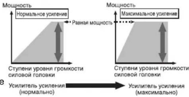
Gaincontrolofthisunit
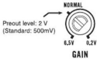
AboveillustrationsshowsNORMALgainsetting.
Relationshipbetweenamplifiergain andheadunitoutputpower
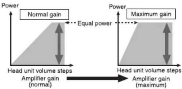
If amplifiergainisraisedimproperly,thiswill simplyincreasedistortion,withlittleincrease inpower.
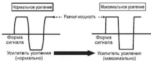
Signalwaveformwhenoutputting at highvolumeusingamplifiergain control
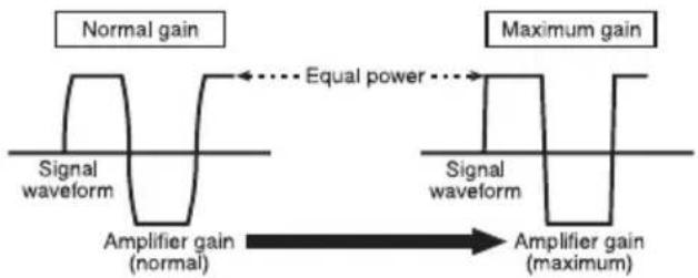
Signalwaveformdistortedwithhighoutput,if youraisethegainoftheamplifierthepower changesonlyslightly.
Connectingtheunits
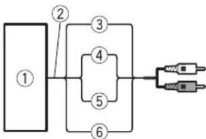
Connectiondiagram
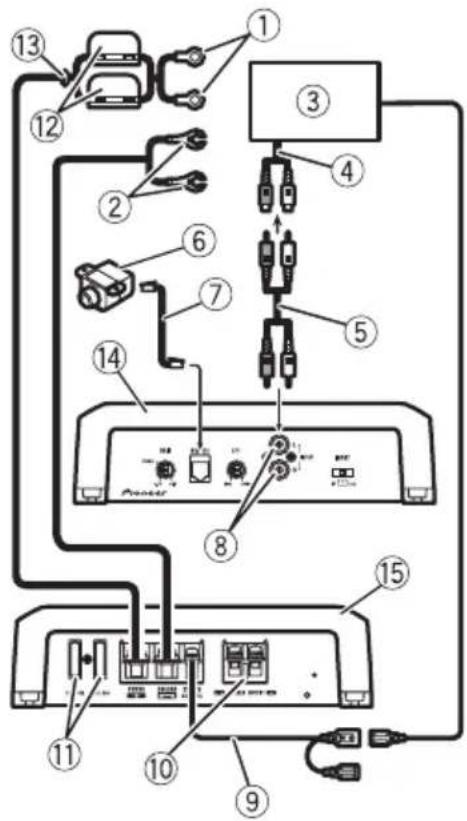
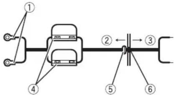
①Specialredbatterywire RD-223(soldseparate
Aftercompletingallotheramplifierconnections,finallyconnectthebatterywireterminal oftheampliertothepositive () battery terminal.
②Groundwire(Black)
RD-223(soldseparately)
Connecttoaclean,paint-freemetallocation.
③ CarstereowithRCAoutputjacks(soldseparately)
④ Externaloutput
⑤ConnectingwirewithRCApinplugs(soldseparately)
⑥ Bassboostlevelremotecontrol
⑦ Bassboostlevelremotecontrolwire(6m)
⑧RCAinputjack
Systemremotecontrolwire(soldseparately) Connectmaleterminalofthiswiretothesystemremotecontrolterminalofthecarstereo. Thefemaleterminalcanbeconnectedtothe
auto-antennarelaycontrolterminal.Ifthecar stereolacksystemremotecontrolterminal, connectthemaleterminaltothepowerterminalviaitheignitionswitch.
10Speakeroutputterminals Pleaseseethefollowingsectionforspeaker connectioninstructions.RefertoConnections whenusingthespeakerinputwireonthenthenthpage.
①Fuse(30A)×2
⑫Fuse(30A)×2
⑬Grommet
(4)Rearside
15Frontside
Beforeconnectingthe amplifier
WARNING
- Securethewiringwithcableclampsoradhesivetape. Toprotecttthewiring,wrapsections incontactwithmetalpartsinadhesivetape.
- Nevercuttheinsulationofthepowersupply tofeedpowertootherequipment.Current capacityoftthewireislimited.
CAUTION
- Nevershortenanywires, the protection circuit may malfunction.
- Neverwirethespeakernegativecabledirectly-toground.
- Neverbandtogethermultiplespeaker'snegativecables.
- Ifthesystemremotecontrolwireoftheamplifierisconnectedtothepowerterminalviathe ignitionswitch(12VDC),theamplifierwillremainonwiththeignitionwhetherstearstereoisonoroff,whichmayexhaustbattery iftheengineisatrestoridling.
Connectingtheunits
Installandroutetheseparatelysoldbattery wireasfaraspossiblefromthespeakerwires. Installandroutetheseparatelysoldbattery wire,groundwire,speakerwiresandthemplifierasfarawayaspossiblefromtheantenna,antennacableandtuner.
Connectingthespeakers
Connectthespeakerleadstosuitthemode accordingtothefiguresshownbelow.
One-channeloutput
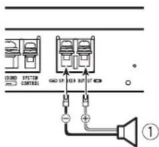
①Subwoofer
Connectionswhenusing thespeakerinputwire
Connectthecarstereospeakeroutputwires totheamplifierusingthesuppliedspeaker inputwirewithRCApincord.
①CarStereo
②Speakeroutput
③Red:Right
④Black:Right
⑤Black:Left-
⑥White:Left
⑦SpeakerinputwirewithRCApincord TotheRCAinputjackofthisunit

Note
- If speaker wires with an RCA pincord from a headunit are connected to this amplifier, the amplifier will automatically turn on when the headunit is turned on. Whenthe headunit is turned off, the amplifier turns off automatically. This function may not work with some headunits. Insuch cases, please use asystemremotecnrolwire(sold separately). If multiple amplifiers are connected togethersynchronously, connect the headunit and all amplifier viathesystemremotecntrlwire.
- Connectthesystemremotecontrolwirewhen youwishtoonlyturnnonthecarstereo.notthe amplifier.
Connectingtheunits
Connectingthepowerterminal
Theuseofaspecialredbatteryandground wireRD-223,availableseparately,isrecommended.Connectthebatterywiredirectly tothecarbatterypositiveterminal () and thegroundwiretothecarbody.

WARNING
If the battery wire is not securely fixed to the terminal using the terminals screws, there is a risk of overheating, malfunction and injury, including minor burns.
1Routebatterywirefromenginecompartmenttothevehicleinterior.
Aftercompletingallotheramplifierconnections,finallyconnectthebatterywireterminal oftheampliertothepositive () battery terminal.
Positive( )terminal
② Enginecompartment
③ Vehicleinterior
④Fuse(30A)×2
⑤ InserttheO-ringrubbergrommetintothe vehiclebody.
⑥ Drilla14mmholeintothevehiclebody.
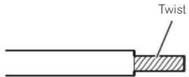
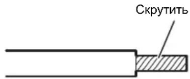
2Twistthebatterywire,groundwire andsystemremotecntrlwire.
3Attachlugstowireends.Lugsnotsupplied.
Usepliers,etc.,tocrimplugstowires.
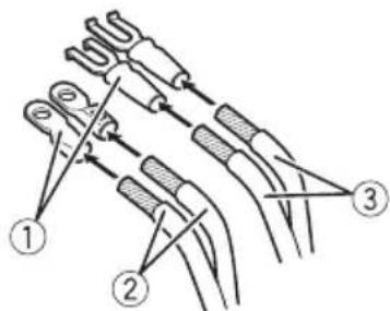
①Lug
② Batterywire
③Groundwire
4Connectthewirestotheterminal.
Fixthewiressecurelywiththeterminal screws.
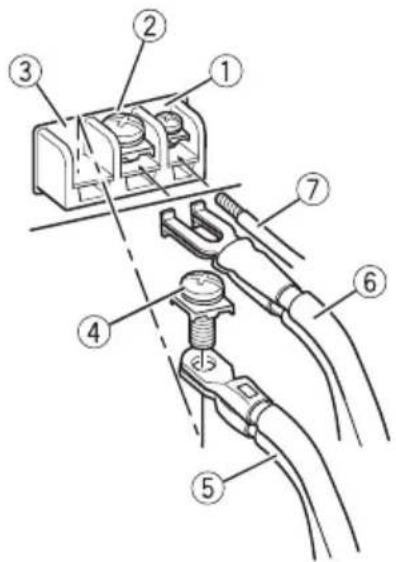
①Systemremotetocontrolterminal
②GNDterminal
③Powerterminal
Connectingtheunits
④Terminalscrews
⑤Batterywire
⑥Groundwire
⑦Systemremotecontrolwire

Connectingthespeaker outputterminals
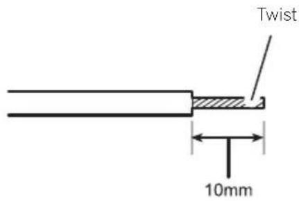
1Exposetheendofthespeakerwires usingnippersoracutterbyabout10mm andtwist.
2Attachlugstospeakerwireends.Lugs notsupplied.
Usepliers,etc.,tocrimplugstowires.
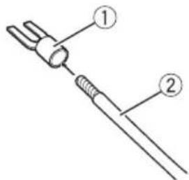
①Lug
②Speakerwire
3Connectthespeakerwiresthespeakeroutputterminals.
Fixthespeakerwiressecurelywiththeterminalscrews.
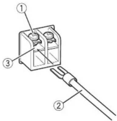
①Terminalscrews
②Speakerwires
③Speakeroutputterminals
Beforeinstallingtheamplifier

WARNING
- Donotuseunauthorizedpartsasthismay causemalfunctions.
- Donotinstallthisunitwhere:
-itmayinterferewithoperationofthevehicle.
-itmaycauseinjurytoapassengersaresultofasuddenstop.
Installtappingscrewsinsuchawaythatthe screwtipdoesnn'touchanywire.Thisisimportanttopreventwiresfrombeingcutbyvibrationofthecar,whichcanresultinfire. - Placeallcablesawayfrommovingparts,such asthegearshiftandseatrails.
- Whendrillingtoinstalltheamplifier,always confirmnopartsarebehindthepaneland protectallcablesandimportantequipment (e.g.fuel/brakelines,wiring)fromdamage.

CAUTION
Toensureproperheatdissipationoftheamplifier,ensurethefollowingduringinstallation:Allowadequatespaceabovetheamplifierforproperventilation.Donotcovertheamplifierwithafloormat orcarpet.
- Placeallcablesawayfromhotplaces,such asneartheheateroutlet.
Theoptimalinstallationlocationdiffersdependingonthecarmodel.Securethempliferatasufficientlyrigidlocation.
- Checkallconnectionsandsystemsbefore finalinstallation.
Afterinstallingtheamplifier, confirmthat the spare tire, jackandtoolscanbeeasilyremoved.
AttachingtheBassboost remotecontrol
Attachwithtappingscrews(3mm×10mm) ataneasilyaccessiblelocationssuchasunder thedashboard.
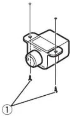
①Tappingscrews(3mm×10mm)

Exampleofinstallationon thefloormatorchassis
1Placethemplifierinthedesiredinstallationlocation.
Insertthesuppliedtappingscrews(4mm× 18mm)intothescrewholesandpushonthe screwswithascrewdriversotheymakeanimprintwheretheinstallationholesaretobelocated.
2Drill2.5mm diameter holes at the imprintseither on the carpetordirectly on the chassis.
3Installtheamplifierwiththeuseof suppliedtappingscrews(4mm×18mm).
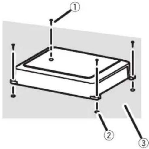
①Tapping-screws(4mm×18mm)
②Drilla2.5mm diameterhole
③Floormatorchassis
Additionalinformation
Specifications
Powersource.14.4VDC(10.8Vto15.1V allowable)
Groundingsystem.. Negativetype
Currentconsumption.27A(atcontinuouspower, 4Ω)
Averagecurrentdrawn.....7.5A4Qforonechannel) 15A(2Qforonechannel)
Fuse. 30A×2
Dimensions(W×H×D)...310mm×56mm×200 mm
Weight. 2.8kg(Leadsforwiringnot included)
Maximum power output ....600 W × 1 (4 Ω) / 1 200 W × 1 (2 Ω)
Continuouspoweroutput...300W×1(at14.4V,4Ω,2.0 Hzto240Hz,≤1%THD)
600W×1(at14.4V,2Ω,50 Hz,≤1%THD)
Load impedance 4Ω (2Ω to 8Ω allowable)
Frequencyresponse.10Hzto240Hz(+0dB,3 dB)
Signal-to-noiseratio.80dB(IEC-Anetwork) Distortion.0.3%(10W,100Hz)
Lowpassfilter: Cutofffrequency.40Hzto240Hz Cutoffslope.12dB/oc
Bassboost: Frequency. .50Hz Level. 0dBto12dB
Gaincontrol:
RCA.200mVto6.5V
Speaker.0.8Vto26V
Maximuminputlevel/impedance: RCA. .6.5V/22kΩ Speaker. .26V/90kΩ

Notes
- Specificationsandthedesignaresubjecttomodificationswithoutnotice.
Theaveragecurrentdrawnisnearlythemaximumcurrentdrawnbthisunitwhenanaudiosignalisinput.Usethisvaluewhenworkingouttotalcurrentdrawnbymultiplepoweramplifiers.
Accentuationdesgraves: Frquence. .50Hz Niveau.. 0dBa12dB
Commandedegain: RCA. 200mVa6,5V Haut-parleur. 0,8Va26V
Niveaudentreemaximal/impedance: RCA. 6,5V/22kΩ Haut-parleur. 26V/90kΩ

Remarques
Deversterkingsfactor (gain)instellen
YcTaHOBka KO3ΦΦnUeHtayCnIeHn78
YCTaHOBka NylbTa DnCTaHNoHHoro
ynpaBHeHn ypoBHeM ycNHeHn Hn3Knx
yactot 84
PpIMep yCTaHOBKn yCnIITeHa
HANOJIbHOM KOBpIke IJIN Jaccn 85
- DononHHTeJbHa HcOpMaun
TexHueeckne xapaKTepeNCTnKn 86
YcTaHOBKa Ko3ΦΦnUeHtayCnJIeHnIy
B yctpoicBe npedymotpeHa cyHKcna 3aunbl OT yCTaHOBKn CnHsKOM BbICOKo MOuHOCn,HeBepHOrO nCNoIb3OBaHn INn HeBepHOro nOdknUoyehn,CnocO6hIX npNBecTN K BbIXOy ycNlnteY n3 cTpor.
-Prn yctaHOBe CNIshKOM BbICOKOуpoB-HrPOMKOCTn N T.I.DaHHaФyHKunHa HECKoJIbKO CeKYHd OTKIOUaET 3Byk (3TO HeBJIaETcH HeNCpPaBHOCTbIO)N BHOBb BKIOUaET erO npn CHNXeHNu yPOBHr rPOMKOCTn Ha rIaNbHOM yCTPOINCTBe.
OTKIOUeHHe 3Byka MoKeT O3HaauTaB, YoCTaHOBJIeH HeBepHbI KO3OoHcIeHT YcINJeHra.4To6bl 3Byk He OTKIOUaJcR npu yCTaHOBKe MaKcIMaJIbHOrO yPOBn rPOMKOCTn Ha OCHOBHOM yCTpOJCTBe,Ko-3oOoHcIeHT YcINJeHra yCINITeJIa DOJKeH COOTBETCTBOBaTb MaKcIMaJIbHOMy yPOB-H IO BbIXoIHOn MOUHOCTn OCHOBHOrO yCTpOJCTBa.B 3tOM cIyuae yPOBEh rPOMKOCTn He 6yJeT n3MeHЯTbcra,a Ko3oOoHcIeHT YcINJeHra He 6yJeT npeBbIaTaB DOYCTMOrO 3HaueHra.
- YpOBeHb rPOMKoCTn N KOaФΦuIeHT yCJIeHnY yCTaHOBJIeHbI npaBnJIbHO,HO 3Byk BCE paBHO nepNoDiuYeCKN OTKnIOUaETcR.B 3TOM cnyae o6paTntEcB B 6nIXaII m ABTOpN3OBAHHbI CepBnCHbI ueHTp Pioneer.
Pereynpobka Ko3phiueneHa ycHJeHn DaHHoro yCTpoiCTBa

Ha pucyHke Bblie noka3aHO noIoxKeHne peryIaTopa ycIIeHnHa ypOBHe NORMAL.
OTHOWeHne KO3ΦΦnUeHTa yCNJIeHnYcNJIteJI N BBIXoHDH MoUHOCTHOCHOBHOrO yCTpOJCTBa
Pn ype3MepHom NOBbIeHnn KO3ΦΦNueH-Ta ycJIeHn pe3Ko YBeJIuHBAHTcNCKaKeHn,a MOUHOCTb NOBblAeTcH3HaHTeNbHO.
ΦopMa cnHana Ha BbIXOe npn BBICOKOM yPOBHe rPOMKOCTN, CO3daHHOM C NOMOuIOp peYJrTopa KO3ΦΦnUeHTa ycJIeHnYcNlnteJIa
NckaxeHHa φopMa cnHaJa npn BbICOKOM ypOBHe rPOMKocTn.Ppn NOBbiUeHn KO3Φ-ΦnCneHTa ycJIeHn YcNJNTeJr MOuHOCTb N3MeHReTc He3HaYtTeJbHo
Ipeed nodkloucheHneM ycnJInteJ
PPEyPExKDeHne
3aKpeHnTe npoBoda npn NOMOu 3axmOB nINn IN3OJauNHOHOn JeHTbI.DJIa3aUNTbI npoBODKn 3aN3OJInpyuTe npoBoda B MecTx nx COpNIKOCHOBeHnC MeTaJIInueCKMn DeTaJIaMn.
He Hapuatae n3oJauIO npoBdoB nTuHnnaIpaunnHa npyrooe obopyoBaHne.IpoBda mEOT orpaHueHHyO dony-CTmMyHO Harpy3Ky no TOKy.
2CkpTyTe orOleHHbIe KOHcbl npOBoDa, npeHa3NaueHHoro DnI NOKJIuOeHHN K KaKymyTOpY, npOBoDa 3a3eMJIeHHN I npOBoDa CnCTeMbI DnCTaHcNoHHOrO ynpabJeHH.
3HaedeHbTe HaKOHeuHNKn Ha KOHcbl npoBODOB.HaKOHeuHNKn B KOMnIeKT NOCTaBKN He BXOJrT.
IcToUHnK nTaHnA 14,4B NoctOraHHoro ToKa
(DOnyctmbln Dnana3OHOT
10,8Bdo15,1B)
Custema 3a3emnene ...3a3emnene OtpuataeB-
HORO NOJIOCA
IopTe6nembTOK 27AnpHOMHaBHO
BbIXoHON MOUHOCTn,4Ω)
CpeJHee 3HaueHne ToKa ...7,5A(4ΩДЯ OJHOrO Ka-Hana)
15A(2ΩДЛЯ OДнOrO KaHa-
na)
Плавkin npedoxpanHTeIb
30A × 2
Pa3Mepbl (U X B X Γ) 310 × 56 × 200 MM
Bec 2,8 kr (6e3 yyeTa npoBOIOB)
MaKcImaIbHaB BbIXoHra MoUHOCTb
600BTx1(4Ω)/1200BT
× 1(2)
HomHaJIbHaB BbIXOHaH MaOHCTb
300BTX1npn14,4B,4
Ω,OT20Γu do 240Γu,cym
Maphoe 3haeHne KO30
UeHTa HeINHeHbIX
nckaKeHn≤1%)
600 B T × 1 (πρι n 14,4 B, 2
Ω,50Γu,cymMpaHoe3Ha-
YeHHe Ko3oΦΦnUeHNTa
HeINHeHbIX NCKaXeHn ≦
1%)
ConpoTnBJIeHne Harpy3Kn
4Ω(DOnyuctmo-ot2Ω
do 8Ω)
AmnntyduHo-yactothar xapaKTepeNtka
or 10 T do 240 T (+0 d6,
-3D6)
OTHOSeHHe CnHn/7yM .... 80 nB (ceTb IEC-A)
UckaxKeHne 0,3% (10 Bt, 100 Tc)
HnBtp Hn3Knx YactOT:
Yactota cpe3a .ot 40 Tuo 240 T
KpyTu3Ha xapaKTePncTnKn cpe3a
-12D6/okT
YcJIeHHe HIXHX 3ByKOBbIX qACTOT:
Yactota 50u
YpOBeHb .0T0D6do12D6
PeryInpobKa Ko3ΦΦnIeHtA yCnJIeHnIa:
RCA 200 MBdo6,5B
PpOMKOrOBOpnteIb ....ot 0,8 B Do 26B
Makcimambna amnntya BXoHoro cnHana /conpoTNBJIeHne:
RCA 6,5B/22KΩ
TpomkoOBopntb 26 B/90 kΩ
Приимechаиме:
B COOTBETCTBNN CO CTABeN 53aKoHa Pocnckon Fedepaun "O 3aunTe npab noTpe6nteJn NocTaHOBLeHneM npaNTeJIbCTBa Pocnckon Fedepaun No720ot 16.06.97kompanna PioneerEurope NVorOBapnBaet cJeDyUoNc pOK cIyXbbln3deJn,oPhiuaNbHO nOCTaBJaEMbIX Ha poccnckn pbHok.
ABTomo6nIbHa 3neKtpOnHka:6JeT
Дугп e n3dJIeNn (HayuHnKn,MuKpOΦoHbI n
t.n.):5net

PpmeaHnA
XapakTepeNtKn N KOHCTpyKuMOryT 6bITb n3MeHeHbI 6e3 PpeDbapnteJbHoro yBeDOMJIeHn.
CpeHHee 3NaueHHe TOka 6nI3KO K MaKcIMaJIbHOMy 3NaueHIno TOka,Notpe6JrEmomy DaHHbIM yCTpOInCTBOM,KOrDa Ha BXoI NOJaEtCay aynocinHan.IcnoJb3yIte 3TO 3NaueHHe npi NODcTe cyMMapHoro TOKa, Notpe6JrEmoro HeckoJIbKIMN ycINITeJrMM MOUHOCTN.
-Данhoe yctpoiCTBO npOn3BeJeHO B Kntae.

http://www.pioneer.eu
Visit www.pioneer.co.uk (or www.pioneer.eu) to register your product. Visitez www.pioneer.fr (ou www.pioneer.eu) pour enregistrer votre apparéil. Si prega di visitare il site www.pioneer.it (o www.pioneer.eu) per registrarile il prodotto. Visit www.pioneer.es (o www.pioneer.eu) para registrar su producto. Zum Registrieren Ihres Produktés besuchen Sieitte www.pioneer.de (oder www.pioneer.eu). Bezoek www.pioneer.nl (of www.pioneer.eu) om uw producte te registrareren. Nocétinte www.pioneer-rus.ru (ил www.pioneer.eu)對於 picaquin npno6pehenhoro Bamn nndenna.
PIONEERCORPORATION
4-1.MEGURO1-CHOME,MEGURO-KU
TOKYO153-8654,JAPAN
Kopnpaun Paonnp
4-1, Merypo 1-Home, Merypo-Ky, Tokno
153-8654,Яюня
PIONEERELECTRONICS(USA)INC.
P.O.Box1540,LongBeach,California90801-1540,U.S.A.
TEL:(800)421-1404
PIONEEREUROPENV
Haven1087,Keetberglaan1,B-9120Melsele,Belgium/Belgique
TEL:(0)3/570.05.11
PIONEERELECTRONICSASIACENTREPRETLED.
253AlexandraRoad,#04-01,Singapore159936
TEL:65-6472-7555
PIONEERELECTRONICSAUSTRALIAPTY.LTD.
178-184BoundaryRoad,Braeside,Victoria3195,Australia
TEL:(03)9586-6300
PIONEERELECTRONICSOFCANADA,INC.
300AllstateParkway,Markham,OntarioL3R0P2,Canada
TEL:1-877-283-5901
TEL:905-479-4411
PIONEERELECTRONICSDEMEXICO,S.A.deC.V.
PublishedbyPioneerCorporation. Copyright©2009byPioneerCorporation. Allrightsreserved.
PrintedinChina ImpriméenChina
YRD5307-A/S>E W


- ThankyouforpurchasingthisPIONEERproduct.
- Beforeyoustart
- SettingtheUnit
- Connectingtheunits
- Installation
- Additionalinformation
- Incaseoftrouble
- AboutThisProduct
- Beforeconnecting/ installingtheamplifier
- WARNING
- CAUTION
- What'swhat
- ①Powerindicator
- ② GAIN(gain)control
- ③REMOTE(bassboostlevelremotecontrol)jack
- LPF(low-passfilter)cutofffrequency control
- ⑤INPUT(input)switch
- Settinggainproperly
- Gaincontrolofthisunit
- Relationshipbetweenamplifiergain andheadunitoutputpower
- Signalwaveformwhenoutputting at highvolumeusingamplifiergain control
- Connectiondiagram
- Beforeconnectingthe amplifier
- Connectingthespeakers
- One-channeloutput
- Connectionswhenusing thespeakerinputwire
- Note
- Connectingthepowerterminal
- 1Routebatterywirefromenginecompartmenttothevehicleinterior.
- 2Twistthebatterywire,groundwire andsystemremotecntrlwire.
- 3Attachlugstowireends.Lugsnotsupplied.
- 4Connectthewirestotheterminal.
- Connectingthespeaker outputterminals
- Beforeinstallingtheamplifier
- AttachingtheBassboost remotecontrol
- Exampleofinstallationon thefloormatorchassis
- Specifications
- Notes
- Remarques
- Deversterkingsfactor (gain)instellen
- - DononHHTeJbHa HcOpMaun
- YcTaHOBKa Ko3ΦΦnUeHtayCnJIeHnIy
- Pereynpobka Ko3phiueneHa ycHJeHn DaHHoro yCTpoiCTBa
- OTHOWeHne KO3ΦΦnUeHTa yCNJIeHnYcNJIteJI N BBIXoHDH MoUHOCTHOCHOBHOrO yCTpOJCTBa
- ΦopMa cnHana Ha BbIXOe npn BBICOKOM yPOBHe rPOMKOCTN, CO3daHHOM C NOMOuIOp peYJrTopa KO3ΦΦnUeHTa ycJIeHnYcNlnteJIa
- Ipeed nodkloucheHneM ycnJInteJ
- PPEyPExKDeHne
- Приимechаиме:
- PpmeaHnA
- http://www.pioneer.eu
- PIONEERCORPORATION
- Kopnpaun Paonnp
Brand : PIONEER
Model : GMD8500M
Category : AV receiver