SDMHS94P - Monitor SONY - Free user manual and instructions
Find the device manual for free SDMHS94P SONY in PDF.

User questions about SDMHS94P SONY
0 question about this device. Answer the ones you know or ask your own.
Ask a new question about this device
Download the instructions for your Monitor in PDF format for free! Find your manual SDMHS94P - SONY and take your electronic device back in hand. On this page are published all the documents necessary for the use of your device. SDMHS94P by SONY.
USER MANUAL SDMHS94P SONY
natural_image
Technical line drawing of a mechanical assembly with no visible text or symbolsSDM-HS94/SDM-HS94P
natural_image
Technical line drawing of a mechanical component with no visible text or symbolsnatural_image
Illustration of hands holding a tablet with a curved arrow icon on the screen (no text or symbols)natural_image
Two-panel image showing a striped pattern before and after transformation, with no visible text or symbols.text_image
INFORMATION CABLE DISCONNECTED INPUT1:DVI-D本機の症状と対処のしかた
This display is designed for use in Japan only and cannot be used in any other country.
主な仕様
SDM-HS74/HS74P
Operating Instructions_
GB
SDM-HS74
SDM-HS94
SDM-HS74P
SDM-HS94P
Owner's Record
The model and serial numbers are located at the rear of the unit. Record these numbers in the spaces provided below. Refer to them whenever you call upon your dealer regarding this product. Model No. ____ Serial No. ____
WARNING
To prevent fire or shock hazard, do not expose the unit to rain or moisture.
Dangerously high voltages are present inside the unit. Do not open the cabinet. Refer servicing to qualified personnel only.
FCC Notice
This equipment has been tested and found to comply with the limits for a Class B digital device, pursuant to Part 15 of the FCC Rules. These limits are designed to provide reasonable protection against harmful interference in a residential installation. This equipment generates, uses, and can radiate radio frequency energy and, if not installed and used in accordance with the instructions, may cause harmful interference to radio communications. However, there is no guarantee that interference will not occur in a particular installation. If this equipment does cause harmful interference to radio or television reception, which can be determined by turning the equipment off and on, the user is encouraged to try to correct the interference by one or more of the following measures:
– Reorient or relocate the receiving antenna.
– Increase the separation between the equipment and receiver.
- Connect the equipment into an outlet on a circuit different from that to which the receiver is connected.
- Consult the dealer or an experienced radio/TV technician for help. You are cautioned that any changes or modifications not expressly approved in this manual could void your authority to operate this equipment.
IMPORTANTE
If you have any questions about this product, you may call; Sony Customer Information Services Center 1-800-222-7669 or http://www.sony.com/
Declaration of Conformity
Trade Name: SONY
Model: SDM-HS74
SDM-HS94
SDM-HS74P
SDM-HS94P
Responsible Party: Sony Electronics Inc.
Address: 16450 W. Bernardo Dr,
San Diego, CA 92127 U.S.A.
Telephone Number: 858-942-2230
This device complies with part 15 of the FCC rules. Operation is subject to the following two conditions: (1) This device may not cause harmful interference, and (2) this device must accept any interference received, including interference that may cause undesired operation.
NOTICE
This notice is applicable for USA/Canada only.
If shipped to USA/Canada, install only a UL LISTED/CSA
LABELLED power supply cord meeting the following specifications:
SPECIFICATIONS
Plug Type Nema-Plug 5-15p
Cord Type SVT or SJT, minimum 3 · 18 AWG
Length Maximum 15 feet
Rating Minimum 7 A, 125 V
NOTICE
As an ENERGY STAR Partner, Sony Corporation has determined that this product meets the ENERGY STAR guidelines for energy efficiency.
Table of Contents
Precautions....4
Identifying parts and controls 5
Setup....7
Step 1: Connect the display to your computer ..... 7
Step 2: Connect the power cord....8
Step 3: Secure the cords and replace the back cover ..... 8
Step 4: Turn on the monitor and computer .....9
Adjusting the tilt 9
Selecting the input signal (INPUT button)....9
Customizing Your Monitor....10
Adjusting to the desired brightness....10
Navigating the menu....10
Adjusting the backlight (BACKLIGHT) 11
Adjusting the contrast (CONTRAST) 12
Adjusting the black level of an image (BRIGHTNESS)....12
Adjusting the picture's sharpness and centering (SCREEN) (analog RGB signal only) 12
Adjusting the color temperature (COLOR) 13
Changing the gamma setting (GAMMA)....14
Adjusting the sharpness (SHARPNESS) 14
Changing the menu's position (MENU POSITION) ..... 14
Changing the input automatically (INPUT SENSING) ..... 14
Selecting the on-screen menu language (LANGUAGE).....15
Additional settings....15
• Macintosh is a trademark licensed to Apple Computer, Inc., registered in the U.S.A. and other countries.
- Windows ^® and MS-DOS are registered trademarks of Microsoft Corporation in the United States and other countries.
• IBM PC/AT and VGA are registered trademarks of IBM Corporation of the U.S.A.
- VESA and DDC ^TM are trademarks of the Video Electronics Standards Association.
• ENERGY STAR is a U.S. registered mark.
- Adobe and Acrobat are trademarks of Adobe Systems Incorporated.
- All other product names mentioned herein may be the trademarks or registered trademarks of their respective companies.
- Furthermore, “TM” and “®” are not mentioned in each case in this manual.
Technical Features ....16
Power saving function....16
Reducing the power consumption (1-mode) 16
Automatic picture quality adjustment function (analog RGB signal only) 16
Troubleshooting....17
On-screen messages 17
Trouble symptoms and remedies 18
Self-diagnosis function 20
Specifications....21
Precautions
Warning on power connections
- Use the supplied power cord. If you use a different power cord, be sure that it is compatible with your local power supply.
For the customers in the U.S.A.
If you do not use the appropriate cord, this monitor will not conform to mandatory FCC standards.
For the customers in the UK
If you use the monitor in the UK, be sure to use the appropriate UK power cord.
Example of plug types
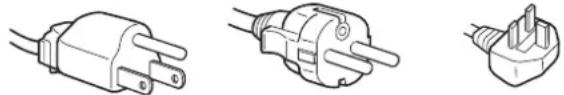
natural_image
Three line drawings of different types of electrical plugs (no text or symbols)for 100 to 120 V AC for 200 to 240 V AC for 240 V AC only
The equipment should be installed near an easily accessible outlet.
Installation
Do not install or leave the monitor:
- In places subject to extreme temperatures, for example near a radiator, heating vent, or in direct sunlight. Subjecting the monitor to extreme temperatures, such as in an automobile parked in direct sunlight or near a heating vent, could cause deformations of the casing or malfunctions.
- In places subject to mechanical vibration or shock.
- Near any equipment that generates a strong magnetic field, such as a TV or various other household appliances.
- In places subject to inordinate amounts of dust, dirt, or sand, for example near an open window or an outdoor exit. If setting up temporarily in an outdoor environment, be sure to take adequate precautions against airborne dust and dirt. Otherwise irreparable malfunctions could occur.
Handling the LCD screen
- Do not leave the LCD screen facing the sun as it can damage the LCD screen. Take care when you place the monitor by a window.
- Do not push on or scratch the LCD screen. Do not place a heavy object on the LCD screen. This may cause the screen to lose uniformity or cause LCD panel malfunctions.
- If the monitor is used in a cold place, a residual image may appear on the screen. This is not a malfunction. The screen returns to normal as the temperature rises to a normal operating level.
- If a still picture is displayed for a long time, a residual image may appear for a while. The residual image will eventually disappear.
- The LCD panel becomes warm during operation. This is not a malfunction.
Note on the LCD (Liquid Crystal Display)
Please note that the LCD screen is made with high-precision technology. However, black points or bright points of light (red, blue, or green) may appear constantly on the LCD screen, and irregular colored stripes or brightness may appear on the LCD screen. This is not malfunction.
(Effective dots: more than 99.99%)
Maintenance
- Be sure to unplug the power cord from the power outlet before cleaning your monitor.
- Clean the LCD screen with a soft cloth. If you use a glass cleaning liquid, do not use any type of cleaner containing an anti-static solution or similar additive as this may scratch the LCD screen's coating.
- Clean the cabinet, panel, and controls with a soft cloth lightly moistened with a mild detergent solution. Do not use any type of abrasive pad, scouring powder, or solvent, such as alcohol or benzine.
- Do not rub, touch, or tap the surface of the screen with sharp or abrasive items such as a ballpoint pen or screwdriver. This type of contact may result in a scratched picture tube.
- Note that material deterioration or LCD screen coating degradation may occur if the monitor is exposed to volatile solvents such as insecticide, or if prolonged contact is maintained with rubber or vinyl materials.
Transportation
- Disconnect all cables from the monitor and grasp the support and base sections of the display stand firmly with both hands when transporting. If you drop the monitor, you may be injured or the monitor may be damaged.
- When you transport this monitor for repair or shipment, use the original carton and packing materials.
Disposal of the monitor
- Do not dispose of this monitor with general household waste.
- The fluorescent tube used in this monitor contains mercury. Disposal of this monitor must be carried out in accordance to the regulations of your local sanitation authority.
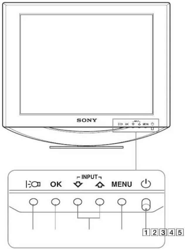
Identifying parts and controls
See the pages in parentheses for further details.
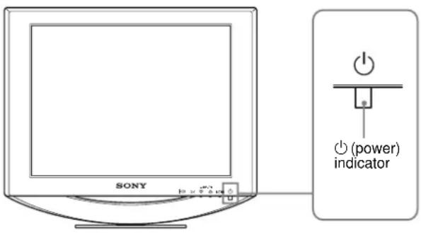
The Ⓗ (power) switch and the control buttons are on the lower right part of the front of the monitor.
Front of the LCD display
text_image
SONY INPUT MENU 1 2 3 4 5Rear of the display
SDM-HS74/SDM-HS74P
natural_image
Technical line drawing of a mechanical assembly with no visible text or symbolsSDM-HS94/SDM-HS94P
natural_image
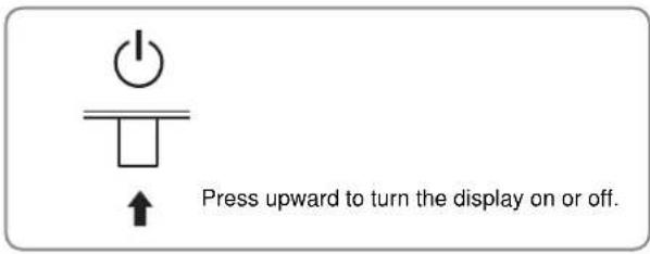
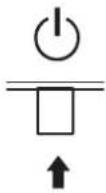
Technical line drawing of a mechanical component with no visible text or symbols1 ⏻ (Power) switch and indicator (pages 9, 16, 20)
To turn the display on or off, press the ⏻ (power) switch upward.
The power indicator lights up in green when the display is turned on, and lights up in orange when the monitor is in power saving mode.
text_image
Press upward to turn the display on or off.②MENU button (pages 10, 11)
This button displays or closes the main menu.
3↓/↑ buttons (page 11)
These buttons function as the ↓/↑ buttons when selecting the menu items and making adjustments.
Also these buttons switch the video input signal between INPUT1 and INPUT2 when two computers are connected to the monitor. (Only available when menu is turned off.)
4 OK button (page 11)
This button selects the item or executes the settings in the menu.
5 button (page 10)
This button is used to change the brightness of the screen.
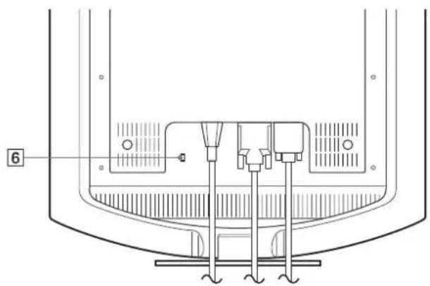
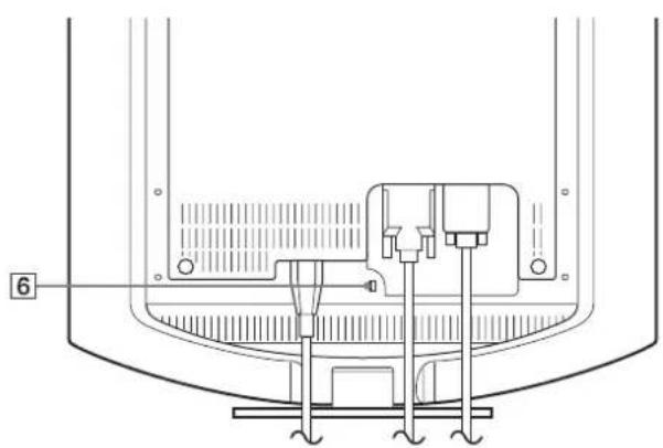
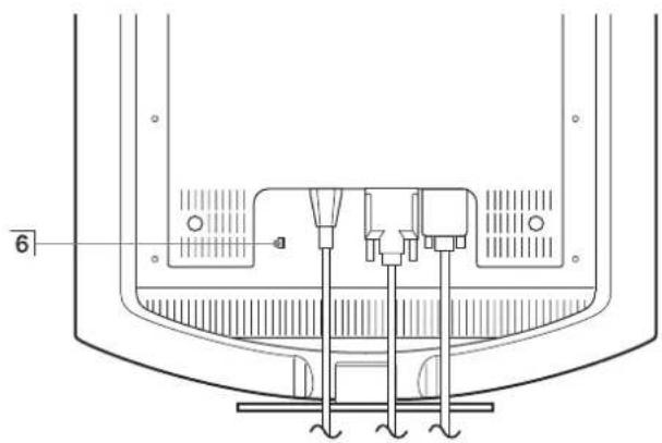
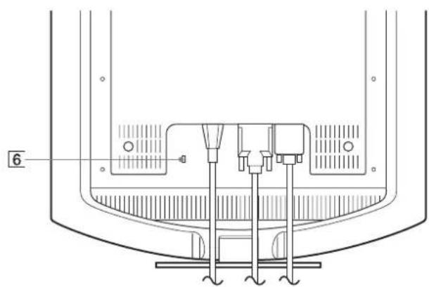
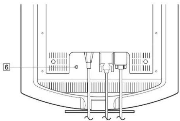
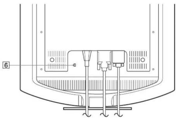
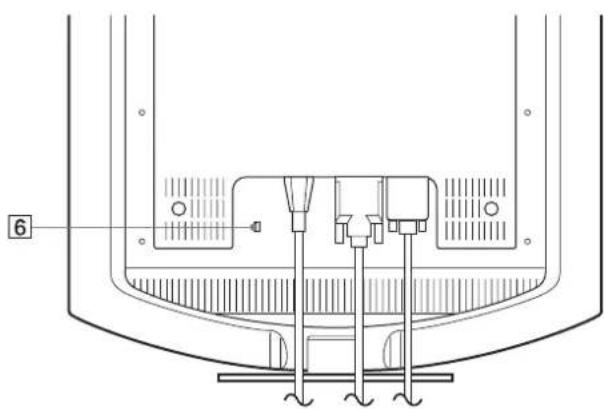
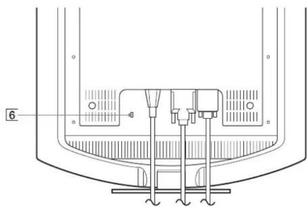
6 Security Lock Hole
The security lock hole should be applied with the Kensington Micro Saver Security System.
Micro Saver Security System is a trademark of Kensington.
Rear of the LCD display
text_image
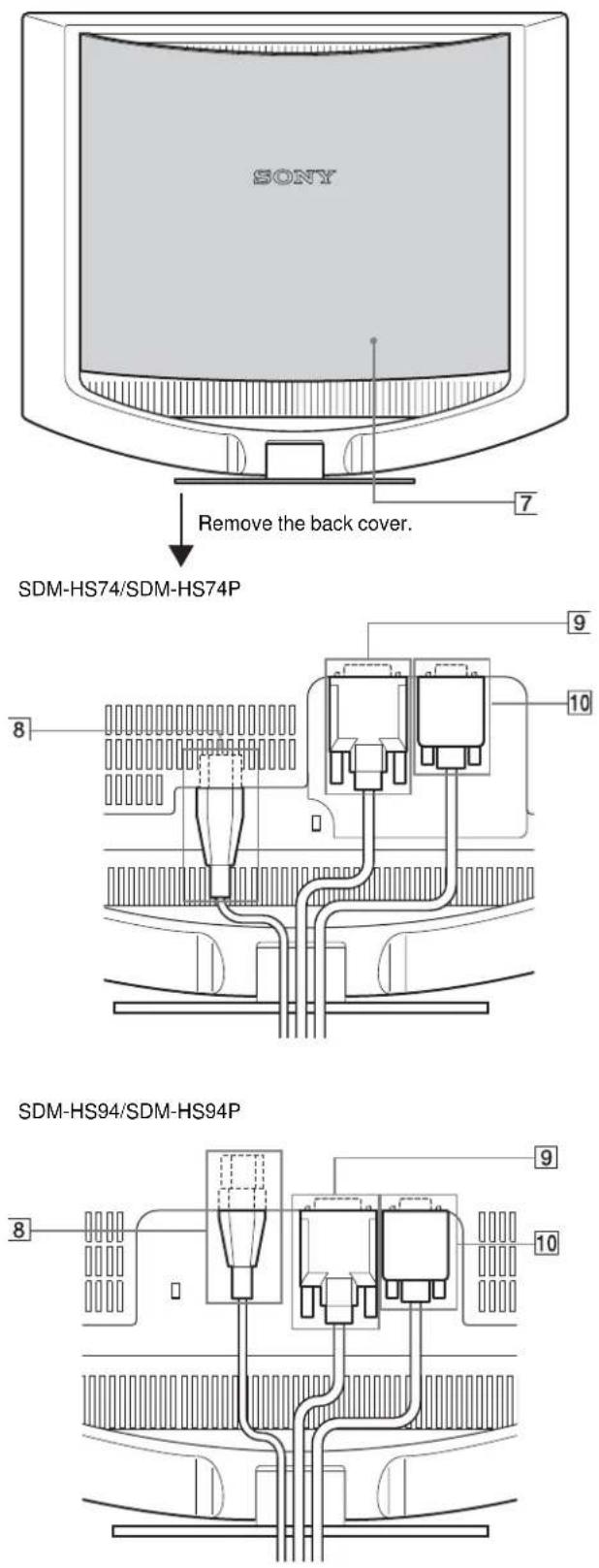
SONY Remove the back cover. SDM-HS74/SDM-HS74P SDM-HS94/SDM-HS94P7 Back cover (page 8)
Remove this cover when you connect/disconnect cables or cords.
8 AC IN connector (page 8)
Connect the power cord (supplied).
⑨ DVI-D input connector (digital RGB) for INPUT1 (page 7)
This connector inputs digital RGB video signals that comply with DVI Rev.1.0.
10 HD15 input connector (analog RGB) for INPUT2 (page 7)
This connector inputs analog RGB video signals (0.7 Vp-p, positive) and SYNC signals.
Setup
Before using your monitor, check that the following items are included in your carton:
• LCD display
- Power cord
• HD15-HD15 video signal cable (analog RGB)
• DVI-D video signal cable (digital RGB)
- Cord strap
- CD-ROM (utility software for Windows/Macintosh, Operating Instructions, etc.)
- Warranty card
- Quick Setup Guide
Step 1: Connect the display to your computer
Turn off the monitor and computer before connecting.
Notes
- Do not touch the pins of the video signal cable connector as this might bend the pins.
- Check the alignment of the HD15 connector to prevent bending the pins of the video signal cable connector.
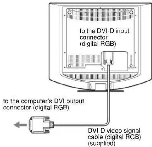
Connect a computer equipped with a DVI output connector (digital RGB)
Using the supplied DVI-D video signal cable (digital RGB), connect the computer to the monitor's DVI-D input connector (digital RGB)
text_image
to the DVI-D input connector (digital RGB) to the computer's DVI output connector (digital RGB) DVI-D video signal cable (digital RGB) (supplied)Connect a computer equipped with an HD15 output connector (analog RGB)
Using the supplied HD15-HD15 video signal cable (analog RGB), connect the computer to the monitor's HD15 input connector (analog RGB).
Connect the computer according to the following illustrations.
■ Connecting to an IBM PC/AT or compatible computer
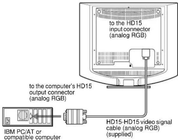
text_image
to the HD15 input connector (analog RGB) to the computer's HD15 output connector (analog RGB) IBM PC/AT or compatible computer HD15-HD15 video signal cable (analog RGB) (supplied)■ Connecting to a Macintosh computer
When connecting this monitor to a Macintosh computer, use the Macintosh adapter (not supplied) if necessary. Connect the Macintosh adapter to the computer before connecting the cable.
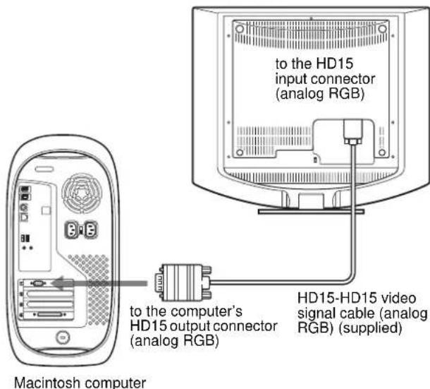
text_image
to the HD15 input connector (analog RGB) to the computer's HD15 output connector (analog RGB) HD15-HD15 video signal cable (analog RGB) (supplied) Macintosh computerStep 2: Connect the power cord
With the monitor and computer switched off, first connect the power cord to the monitor, then connect it to a power outlet. SDM-HS74/SDM-HS74P
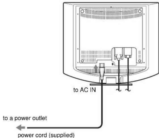
text_image
to a power outlet power cord (supplied) to AC INSDM-HS94/SDM-HS94P
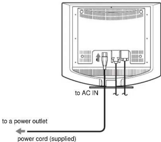
text_image
to a power outlet power cord (supplied) to AC INStep 3: Secure the cords and replace the back cover
1 Bundle the cables and cords.
Using the supplied cord strap, bundle the cables and cords.
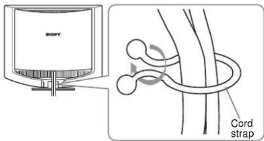
text_image
SONY Cord strapThe illustration of the back of the monitor shown here is that of the SDM-HS74. The same applies for the other models.
2 Replace the back cover.
Step 4: Turn on the monitor and computer
1 Press the ⏻ (power) switch upward.
The ⏻ (power) indicator of the monitor lights up in green.
2 Turn on the computer.
The installation of your monitor is complete. If necessary, use the monitor's controls to adjust the picture.
If no picture appears on your screen
- Check that the power cord and the video signal cable are properly connected.
- If NO INPUT SIGNAL appears on the screen:
The computer is in the power saving mode. Try pressing any key on the keyboard or moving the mouse.
- If CABLE DISCONNECTED appears on the screen:
Check that the video signal cable is properly connected.
• If OUT OF RANGE appears on the screen:
Reconnect the old monitor. Then adjust the computer's graphics board within the following ranges.
| Analog RGB Digital RGB | |
| Horizontal frequency | 28–80 kHz 28–64 kHz |
| Vertical frequency | 48–75 Hz 60 Hz |
| Resolution | 1280 · 1024 or less 1280 · 1024 or less |
For more information about the on-screen messages, see "Trouble symptoms and remedies" on page 18.
No need for specific drivers
The monitor complies with the "DDC" Plug & Play standard and automatically detects all the monitor's information. No specific driver needs to be installed to the computer.
The first time you turn on your computer after connecting the monitor, the setup Wizard may appear on the screen. In this case, follow the on-screen instructions. The Plug & Play monitor is automatically selected so that you can use this monitor.
The vertical frequency turns to 60 Hz.
Since flickers are unobtrusive on the monitor, you can use it as it is. You do not need to set the vertical frequency to any particular high value.
Adjusting the tilt
This display can be adjusted within the angles shown below.
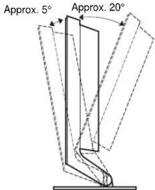
text_image
Approx. 5° Approx. 20°Grasp the lower sides of the LCD panel, then adjust screen tilt.
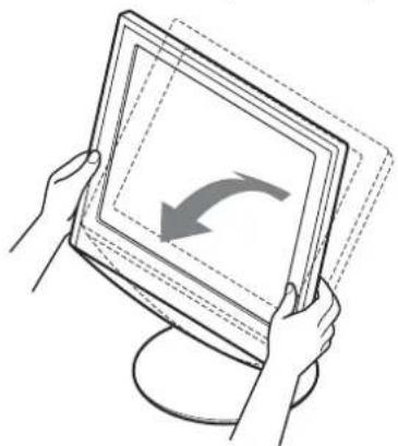
natural_image
Illustration of hands holding a tablet with a curved arrow on the screen (no text or symbols)To use the display comfortably
This display is designed so that you can set it up at a comfortable viewing angle. Adjust the viewing angle of your display according to the height of the desk and chair, and so that light is not reflected from the screen to your eyes.
Selecting the input signal (INPUT button)
Press the ↓/↑ buttons.
The input signal change each time you press these buttons.
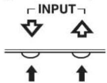
| On-screen message (Appears about 5 seconds on the upper left corner.) | Input signal configuration |
| INPUT1 : DVI-D DVI-D input connector (digital RGB) for INPUT1 | |
| INPUT2 : HD15 HD15 input connector (analog RGB) for INPUT2 | |
Customizing Your Monitor
Before making adjustments
Connect the monitor and the computer, and turn them on. Wait for at least 30 minutes before making adjustments for the best result.
You can make numerous adjustments to your monitor using the on-screen menu.
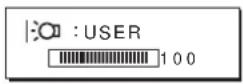
Adjusting to the desired brightness
Pressing the button, you can change the brightness of the screen. Each time you press the button, the mode changes as follows.
HIGH → MIDDLE → LOW → USER → HIGH ...
The brightness of the screen will decrease as the mode setting changes from HIGH to LOW.
If you select USER, you can adjust the backlight level by pressing the ↓/↑ buttons, the same as when you select BACKLIGHT using the menu.
Only while the mode is set to USER, are the BACKLIGHT, CONTRAST, and BRIGHTNESS items of the menu available (page 11).
If you select LOW, the power consumption is reduced (page 16).
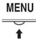
Navigating the menu
Press the MENU button to display the main menu on your screen. See page 11 for more information on using the MENU button.
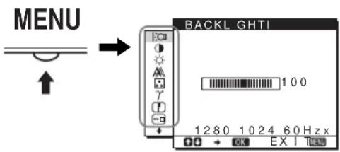
text_image
MENU BACKL GHTI 100 1280 1024 60 Hz x OK EX I MEAUse the ↓/↑ and OK buttons to select the icons in the above main menu illustration. The following 1 to 11 menu appears. Keep pressing ↓ to scroll down until the icons in menu 9 to 11 appear. See page 11 for more information on using the ↓/↑ and OK buttons.
1 BACKLIGHT |:○○ (page 11)
Select the BACKLIGHT menu to adjust the brightness of the backlight.
text_image
BACKL GHTI 100 1280 1024 60 Hz x2 CONTRAST ① (page 12)
Select the CONTRAST menu to adjust the picture contrast.

text_image
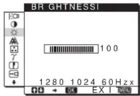
CONTRAST 100 1280 1024 60 Hz x3 BRIGHTNESS (page 12)
Select the BRIGHTNESS menu to adjust the picture brightness (black level).
text_image
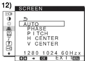
BR GHTNESSI 100 1280 1024 60 Hzx EX I4 SCREEN A (page
Select the SCREEN menu to adjust the picture's sharpness (phase/pitch) or its centering (horizontal/vertical position).
text_image
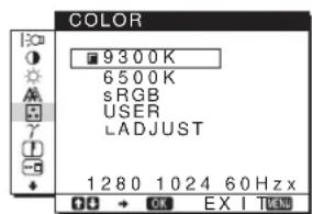
12) SCREEN AUTO PHASE PITCH H CENTER V CENTER 1280 1024 60 Hz5 COLOR (page 13)
Select the COLOR menu to adjust the color temperature of the picture. This adjusts the tone of the screen. While COLOR is set to sRGB, you cannot adjust CONTRAST, BRIGHTNESS or GAMMA.
text_image
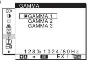
COLOR 9300K 6500K sRGB USER LADJUST 1280 1024 60Hz x6GAMMA γ (page 14)
Select the GAMMA menu to change the picture's color shade setting.
text_image
GAMMA GAMMA 1 GAMMA 2 GAMMA 3 1 2 8 0x 1 0 2 4 / 6 0 Hz DO → OK EX I HANDS7 SHARPNESS (page 14)
Select the SHARPNESS menu to adjust to sharpen the edge of images.

text_image
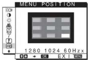
SHARPNESS 1 280x 1 0 24/60 Hz8 MENU POSITION (page 14)
Select the MENU POSITION to change the on-screen menu position.
text_image
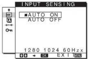
MENU POSITION 1 280 1024 60 Hz x OK EX I9 INPUT SENSING (page 14)
Select the INPUT SENSING menu to change the input automatically before the monitor goes into the power saving mode.
text_image
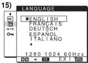
INPUT SENSING ■AUTO ON AUTO OFF 1280 1024 60 Hz x OK EX I Left10LANGUAGE (page
Select LANGUAGE to change the language used on menus or messages.
text_image
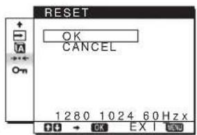
LANGUAGE ■ENGLISH FRANÇAIS DEUTSCH ESPAÑOL ITALIANO + 1280 1024 60Hz x11 Other menus (page 15)
Set the following menu items. - RESET → - MENU LOCK
text_image
RESET OK CANCEL 1280 1024 60 Hzx OK EX I END■ Using the MENU, ↓/↑, and OK buttons
1 Display the main menu.
Press the MENU button to display the main menu on your screen.
2 Select the menu you want to adjust.
Press the ↓/↑ buttons to display the desired menu. Press the OK button to select the menu item.
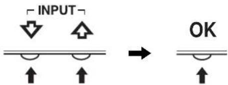
text_image
INPUT OK3 Adjust the menu.
Press the ↓/↑ buttons to make the adjustment, then press the OK button.
When you press the OK button, the setting is stored, then the display returns to the previous menu.
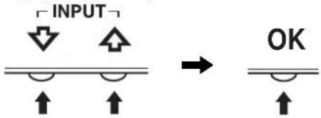
text_image
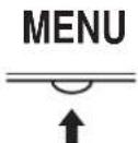
INPUT OK4 Close the menu.
Press the MENU button once to return to normal viewing. If no buttons are pressed, the menu closes automatically after about 30 seconds.
■ Resetting the adjustments
You can reset the adjustments using the RESET menu. See page 15 for more information on resetting the adjustments.
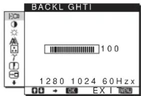
Adjusting the backlight (BACKLIGHT)
If the screen is too bright, adjust the backlight and make the screen easier to see.
Note
The backlight cannot be adjusted when the mode is set to HIGH, MIDDLE, or LOW (page 10).
1 Press the MENU button.
The main menu appears on the screen.
2 Press the ↓/↑ buttons to select ☐ (BACKLIGHT) and press the OK button.
The BACKLIGHT menu appears on the screen.
3 Press the ↓/↑ buttons to adjust the light level and press the OK button.
Adjusting the contrast (CONTRAST)
Adjust the picture contrast.
Note
The contrast cannot be adjusted when the mode is set to HIGH, MIDDLE, or LOW (page 10).
1 Press the MENU button.
The main menu appears on the screen.
2 Press the ↓/↑ buttons to select Ⓐ (CONTRAST) and press the OK button.
The CONTRAST menu appears on the screen.
3 Press the ↓/↑ buttons to adjust the contrast and press the OK button.
Adjusting the black level of an image (BRIGHTNESS)
Adjust the picture brightness (black level).
Note
The brightness cannot be adjusted when the mode is set to HIGH, MIDDLE, or LOW (page 10).
1 Press the MENU button.
The main menu appears on the screen.
2 Press the ↓/↑ buttons to select ⚙ (BRIGHTNESS) and press the OK button.
The BRIGHTNESS menu appears on the screen.
3 Press the ↓/↑ buttons to adjust the brightness and press the OK button.
Adjusting the picture's sharpness and centering (SCREEN) (analog RGB signal only)
Note
When receiving digital RGB signals from the DVI-D input connector, adjustment is not necessary.
■ Automatic picture quality adjustment function
When the monitor receives an input signal, it automatically adjusts the picture's position and sharpness (phase/pitch), and ensures that a clear picture appears on the screen (page 16).
Note
While the automatic picture quality adjustment function is activated, only the ⏻ (power) switch will operate.
If the automatic picture quality adjustment function of this monitor seems to not completely adjust the picture
You can make further automatic adjustment of the picture quality for the current input signal. (See AUTO below.)
If you still need to make further adjustments to the picture quality
You can manually adjust the picture's sharpness (phase/pitch) and position (horizontal/vertical position).
These adjustments are stored in memory and automatically recalled when the display receives the same input signal. These settings may have to be repeated if you change the input signal after reconnecting your computer.
■ Make further automatic adjustments to the picture quality for the current input signal (AUTO)
1 Press the MENU button.
The main menu appears on the screen.
2 Press the ↓/↑ buttons to select ⚪ (SCREEN) and press the OK button.
The SCREEN menu appears on the screen.
3 Press the ↓/↑ buttons to select AUTO and press the OK button.
Make the appropriate adjustments of the screen's phase, pitch and horizontal/vertical position for the current input signal and store them.
4 Press the ↓/↑ buttons to select ↩ and press the OK button.
Return to the menu screen.
■ Adjust the picture's sharpness manually (PHASE/PITCH)
You can adjust the picture's sharpness as follows.
1 Set the resolution to 1280 · 1024 on the computer.
2 Load the CD-ROM.
3 Start the CD-ROM, select the region and model, and display the test pattern.
For Windows
Click [Utility] → [Windows]/[Win Utility.exe].
For Macintosh
Click [Utility] → [Mac]/[Mac Utility].
4 Press the MENU button.
The main menu appears on the screen.
5 Press the ↓/↑ buttons to select ⚪ (SCREEN) and press the OK button.
The SCREEN menu appears on the screen.
6 Press the ↓/↑ buttons to select PHASE and press the OK button.
The PHASE menu appears on the screen.
7 Press the ↓/↑ buttons until the horizontal stripes are at a minimum.
Adjust so that the horizontal stripes are at a minimum.
natural_image
Two-panel image showing a textured surface before and after transformation, with no visible text or symbols.8 Press the OK button.
Return to the SCREEN menu.
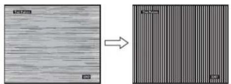
If vertical stripes are observed over the entire screen, adjust pitch by the following steps.
9 Press the ↓/↑ buttons to select PITCH and press the OK button.
The PITCH menu appears on the screen.
10 Press the ↓/↑ buttons until the vertical stripes disappear.
Adjust so that the vertical stripes disappear.
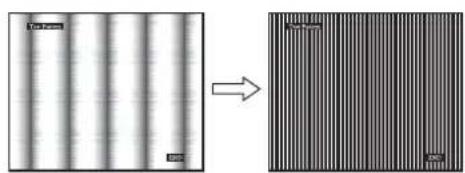
natural_image
Two-panel image showing a striped pattern on the left and a striped pattern on the right, with no visible text or symbols.11 Click END on the screen to turn off the test pattern.
12 Press the OK button.
Return to the SCREEN menu.
13 Press the ↓/↑ buttons to select ↩ and press the OK button.
Return to the menu screen.
■ Adjust the picture's position manually (H CENTER/V CENTER)
If the picture is not in the center of the screen, adjust the picture's centering as follows.
1 Set the resolution to 1280 · 1024 on the computer.
2 Load the CD-ROM.
3 Start the CD-ROM, select the region and model, and display the test pattern.
For Windows
Click [Utility] → [Windows]/[Win Utility.exe].
For Macintosh
Click [Utility] → [Mac]/[Mac Utility].
4 Press the MENU button.
The main menu appears on the screen.
5 Press the ↓/↑ buttons to select ⚪ (SCREEN) and press the OK button.
The SCREEN menu appears on the screen.
6 Press the ↓/↑ buttons to select H CENTER or V CENTER and press the OK button.
The H CENTER or V CENTER menu appears on the screen.
7 Press the ↓/↑ buttons to center the test pattern in the screen.
8 Click END on the screen to turn off the test pattern.
9 Press the OK button.
Return to the SCREEN menu.
10 Press the ↓/↑ buttons to select ↩ and press the OK button.
Return to the menu screen.
Adjusting the color temperature (COLOR)
You can select the color level of the picture's white color field from the default color temperature settings.
Also, if necessary, you can fine tune the color temperature.
You can set the desired color temperature for each mode of the brightness of screen.
1 Press the MENU button.
The main menu appears on the screen.
2 Press the ↓/↑ buttons to select ☐ (COLOR) and press the OK button.
The COLOR menu appears on the screen.
3 Press the ↓/↑ buttons to select the desired color temperature and press the OK button.
Whites will change from a bluish hue to reddish hue as the temperature is lowered from 9300K (default setting) to 6500K.
While "USER" is selected for the brightness of screen, you can set the color temperature to "sRGB."
When you select "sRGB," the colors adjust to the sRGB profile. (The sRGB color setting is an industry-standard color space protocol designed for computer products.) If you select "sRGB," the color settings of your computer must be set to the sRGB profile.
Notes
- If a connected computer or other equipment is not sRGB-compliant, color cannot be adjusted to the sRGB profile.
- While COLOR is set to sRGB, you cannot adjust CONTRAST, BRIGHTNESS or GAMMA.
Fine tuning the color temperature (USER ADJUSTMENT)
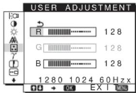
text_image
USER ADJUSTMENT R 128 G 128 B 128 1280 1024 60 Hz x OK EX I1 Press the ↓/↑ buttons to select ADJUST and press the OK button.
The USER ADJUSTMENT menu appears on the screen.
2 Press the ↓/↑ buttons to select R (Red) or B (Blue) and press the OK button. Then press the ↓/↑ buttons to adjust the color temperature and press the OK button.
Since this adjustment changes the color temperature by increasing or decreasing the R and B components with respect to G (green), the G component is fixed.
3 Press the ↓/↑ buttons to select ↗, then press the OK button.
The new color setting is stored in memory for USER and automatically recalled whenever USER is selected.
The main menu appears on the screen.
Changing the gamma setting (GAMMA)
You can associate the picture's color shade on the screen with the picture's original color shade.
1 Press the MENU button.
The main menu appears on the screen.
2 Press the ↓/↑ buttons to select γ (GAMMA) and press the OK button.
The GAMMA menu appears on the screen.
3 Press the ↓/↑ buttons to select the desired mode and press the OK button.
Adjusting the sharpness (SHARPNESS)
Adjust to sharpen the edge of images, etc.
1 Press the MENU button.
The main menu appears on the screen.
2 Press the ↓/↑ buttons to select ☐ (SHARPNESS) and press the OK button.
The SHARPNESS menu appears on the screen.
3 Press the ↓/↑ buttons to adjust the sharpness and press the OK button.
Changing the menu's position (MENU POSITION)
You can change the menu position if it is blocking an image on the screen.
1 Press the MENU button.
The main menu appears on the screen.
2 Press the ↓/↑ buttons to select ☐ (MENU POSITION) and press the OK button.
The MENU POSITION menu appears on the screen.
3 Press the ↓/↑ buttons to select the desired position and press the OK button.
There are three positions each for the top, center and bottom of the screen.
Changing the input automatically (INPUT SENSING)
When you select AUTO ON in the INPUT SENSING menu, the monitor automatically detects an input signal to an input connector, and changes the input automatically before the monitor goes into the power saving mode.
1 Press the MENU button.
The main menu appears on the screen.
2 Keep pressing the ↓ button until the icon of the desired option item appears.
3 Press the ↓/↑ buttons to select (INPUT SENSING) and press the OK button.
The INPUT SENSING menu appears on the screen.
4 Press the ↓/↑ buttons to select the desired mode and press the OK button.
- AUTO ON: When the selected input connector has no input signal, or when you select an input connector by the ↓/↑ buttons on the monitor and the connector has no input signal, the on-screen message appears (page 17) and the monitor checks the input signal to another input connector automatically to change the input. When the input is changed, the selected input connector is displayed on the upper left of the screen. When there is no input signal, the monitor goes into the power saving mode automatically.
- AUTO OFF: The input is not changed automatically. Press the ↓/↑ buttons to change the input.
Selecting the on-screen menu language (LANGUAGE)
You can change the language used on menus or messages displayed on this monitor.
1 Press the MENU button.
The main menu appears on the screen.
2 Keep pressing the ↓ button until the icon of the desired option item appears.
3 Press the ↓/↑ buttons to select A (LANGUAGE) and press the OK button.
The LANGUAGE menu appears on the screen.
4 Press the ↓/↑ buttons to select a language and press the OK button.
• ENGLISH
• FRANÇAIS: French
• DEUTSCH: German
- ESPAÑOL: Spanish
• ITALIANO: Italian
• NEDERLANDS: Dutch
• SVENSKA: Swedish
• : РУСОКИЙ
• : 田本語ese
- 中文:C h i n e s e
Additional settings
You can adjust the following options:
- RESET
- MENU LOCK
1 Press the MENU button.
The main menu appears on the screen.
2 Keep pressing the ↓ button until the icon of the desired option item appears.
3 Press the ↓/↑ buttons to select the desired option item and press the OK button.
Adjust the selected option item according to the following instructions.
■ Resetting the adjustment data to the defaults
You can reset the adjustments to the default settings.
1 Press the ↓/↑ buttons to select →← (RESET) and press the OK button.
The RESET menu appears on the screen.
2 Press the ↓/↑ buttons to select the desired mode and press the OK button.
- OK: To reset all of the adjustment data to the default settings. Note that the ☑LANGUAGE) setting is not reset by this method.
- CANCEL: To cancel resetting and return to the menu screen.
■ Locking the menus and controls
You can lock the control of buttons to prevent accidental adjustments or resetting.
1 Press the ↓/↑ buttons to select O-m (MENU LOCK) and press the OK button.
The MENU LOCK menu appears on the screen.
2 Press the ↓/↑ buttons to select ON or OFF and press the OK button.
- ON: Only the ⏻ (power) switch will operate. If you attempt any other operation, the ⓄMENU LOCK) icon appears on the screen.
- OFF:Set ⬆MENU LOCK) to OFF. If you set the (MENU LOCK) item to ON, only this menu item can be selected.
Technical Features
Power saving function
This monitor meets the power-saving guidelines set by VESA, ENERGY STAR, and NUTEK. If the monitor is connected to a computer or video graphics board that is DPMS (Display Power Management Signaling) compliant, the monitor will automatically reduce power consumption as shown below.
SDM-HS74/SDM-HS74P
| Power mode | Power consumption ⊙ (power) indicator |
| normal operation | 45 W (max.) green |
| active off* (deep sleep)** | 1.0 W (max.) orange |
| power off 1.0 W (max.) off | |
SDM-HS94/SDM-HS94P
| Power mode | Power consumption | + (power) indicator |
| normal operation | 50 W (max.) green | |
| active off* (deep sleep)** | 1.0 W (max.) | orange |
| power off 1.0 W (max.) | off | |
* When your computer enters the “active off” mode, the input signal is cut and NO INPUT SIGNAL appears on the screen. After 5 seconds, the monitor enters the power saving mode.
** "deep sleep" is the power saving mode defined by the Environmental Protection Agency.
Reducing the power consumption
(|m o d e )
If you set the |mode to LOW by pressing the button on the front of the monitor, the backlight level is reduced and the power consumption is reduced, too.
Press the button several times until LOW appears.
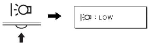
text_image
|:○□ ↓ ↑ → |:○ : LOWLOW appears on the screen and the backlight level is reduced. LOW automatically disappears after about 5 seconds.
Automatic picture quality adjustment function (analog RGB signal only)
When the monitor receives an input signal, it automatically adjusts the picture's position and sharpness (phase/pitch), and ensures that a clear picture appears on the screen.
The factory preset mode
When the monitor receives an input signal, it automatically matches the signal to one of the factory preset modes stored in the monitor's memory to provide a high quality picture at the center of the screen. If the input signal matches the factory preset mode, the picture appears on the screen automatically with the appropriate default adjustments.
If input signals do not match one of the factory preset modes
When the monitor receives an input signal that does not match one of the factory preset modes, the automatic picture quality adjustment function of this monitor is activated to ensure that a clear picture always appears on the screen (within the following monitor frequency ranges):
Horizontal frequency: 28–80 kHz
Vertical frequency: 48–75 Hz
Consequently, the first time the monitor receives input signals that do not match one of the factory preset modes, the monitor may take a longer time than normal to display the picture on the screen. This adjustment data is automatically stored in memory so that next time, the monitor will function in the same way as when the monitor receives the signals that match one of the factory preset modes.
If you adjust the phase, pitch, and picture position manually
For some input signals, the automatic picture quality adjustment function of this monitor may not completely adjust the picture position, phase, and pitch. In this case, you can set these adjustments manually (page 12). If you set these adjustments manually, they are stored in memory as user modes and automatically recalled whenever the monitor receives the same input signals.
Note
While the automatic picture quality adjustment function is activated, only the ⏻ (power) switch will operate.
Troubleshooting
Before contacting technical support, refer to this section.
On-screen messages
If there is something wrong with the input signal, one of the following messages appears on the screen. To solve the problem, see “Trouble symptoms and remedies” on page 18.
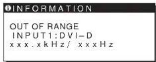
If OUT OF RANGE appears on the screen
This indicates that the input signal is not supported by the monitor's specifications. Check the following items.
text_image
INFORMATION OUT OF RANGE INPUT1:DVI-D xxxx.xkHz/xxxxzIf "xxx.x kHz/xxx Hz" is displayed
This indicates that either the horizontal or vertical frequency is not supported by the monitor's specifications.
The figures indicate the horizontal and vertical frequencies of the current input signal.
If "RESOLUTION > 1280 · 1024" is displayed
This indicates that the resolution is not supported by the monitor's specifications (1280 · 1024 or less).
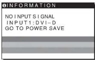
If NO INPUT SIGNAL appears on the screen
This indicates that no signal is being input.
text_image
INFORMATION NO INPUT SIGNAL INPUT1:DVI-D GO TO POWER SAVEGO TO POWER SAVE
The monitor will enter the power saving mode after about 5 seconds from the time the message is displayed.
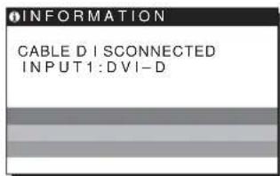
If CABLE DISCONNECTED appears on the screen
This indicates that the video signal cable has been disconnected.
text_image
INFORMATION CABLE DISCONNECTED INPUT1:DVI-DTrouble symptoms and remedies
If a problem is caused by the connected computer or other equipment, please refer to the connected equipment's instruction manual.
Use the self-diagnosis function (page 20) if the following recommendations do not resolve the problem.
| Symptom Check these items | |
| No picture | |
| If the ⏻ (power) indicator is not lit,or if the ⏻ (power) indicator will notlight up when the ⏻ (power) switchis pressed, | ·Check that the power cord is properly connected. |
| If the ⏻ (power) indicator is green, | ·Use the self-diagnosis function (page 20). |
| If CABLE DISCONNECTEDappears on the screen, | ·Check that the video signal cable is properly connected and all plugs are firmly seated intheir sockets (page 7).·Check that the video input connector's pins are not bent or pushed in.A non-supplied video signal cable is connected. If you connect a non-supplied videosignal cable, CABLE DISCONNECTED may appear on the screen before entering thepower saving mode. This is not a malfunction. |
| If NO INPUT SIGNAL appears onthe screen, or the ⏻ (power)indicator is orange, | ·Check that the video signal cable is properly connected and all plugs are firmly seated intheir sockets (page 7).·Check that the video input connector's pins are not bent or pushed in.■Problems caused by a computer or other equipment connected, and notcaused by the monitor·The computer is in the power saving mode. Try pressing any key on the keyboard ormoving the mouse.·Check that your graphics board is installed properly.·Check that the computer's power is on.·Restart the computer. |
| If OUT OF RANGE appears on thescreen, | ■Problems caused by a computer or other equipment connected, and notcaused by the monitor·Check that the video frequency range is within that specified for the monitor. If youreplaced an old monitor with this monitor, reconnect the old monitor and adjust thecomputer's graphics board within the following ranges:Horizontal: 28 – 80 kHz (analog RGB), 28 – 64 kHz (digital RGB)Vertical: 48 – 75 Hz (analog RGB), 60 Hz (digital RGB)Resolution: 1280 · 1024 or less |
| If you are using Windows andreplaced an old monitor with thismonitor, | ·If you replaced an old monitor with this monitor, reconnect the old monitor and do thefollowing. Select “SONY” from the “Manufacturers” list and select “SDM-HS74”,“SDM-HS94P”, “SDM-HS74P” or “SDM-HS94P” from the “Models” list in the Windowsdevice selection screen. If the model name of this monitor does not appear in the“Models” list, try “Plug & Play.” |
| If using a Macintosh system, | ·If you use the Macintosh adapter (not supplied), check that the Macintosh adapter and thevideo signal cable are properly connected (page 7). |
| Picture flickers, bounces,oscillates, or is scrambled | ·Adjust the pitch and phase (analog RGB signal only) (page 12).·Try plugging the monitor into a different AC outlet, preferably on a different circuit.■Problems caused by a computer or other equipment connected, and notcaused by the monitor·Check your graphics board manual for the proper monitor setting.·Confirm that the graphics mode (VESA, Macintosh 19" Color, etc.) and the frequency ofthe input signal are supported by this monitor. Even if the frequency is within the properrange, some graphics boards may have a sync pulse that is too narrow for the monitor tosync correctly.·Adjust the computer’s refresh rate (vertical frequency) to obtain the best possible picture. |
| Picture is fuzzy • Adjust the brightness and contrast (page 12).• Adjust the pitch and phase (analog RGB signal only) (page 12).■ Problems caused by a computer or other equipment connected, and not caused by the monitor• Set the resolution to SXGA (1280 · 1024) on your computer. | |
| Picture is ghosting | • Eliminate the use of video cable extensions and/or video switch boxes.• Check that all plugs are firmly seated in their sockets. |
| Picture is not centered or sized properly (analog RGB signal only) | • Adjust the pitch and phase (page 12).• Adjust the picture position (page 13). Note that some video modes do not fill the screen to the edges. |
| Picture is too small | ■ Problems caused by a computer or other equipment connected, and not caused by the monitor• Set the computer's resolution to the screen's resolution. |
| Picture is dark | • Adjust the brightness using the BRIGHTNESS menu (page 12).• Adjust the backlight (page 11).• Adjust the brightness using the button (page 10).• It takes a few minutes for the display to become bright after turning on the monitor. |
| Wavy or elliptical pattern (moire) is visible | • Adjust the pitch and phase (analog RGB signal only) (page 12). |
| Color is not uniform | • Adjust the pitch and phase (analog RGB signal only) (page 12). |
| White does not look white | • Adjust the color temperature (page 13). |
| Monitor buttons do not operate (Appears on the screen) | • If the menu lock is set to ON, set it to OFF (page 15). |
| The monitor turns off after a while | ■ Problems caused by a computer or other equipment connected, and not caused by the monitor• Set the computer's power saving setting to off. |
| Resolution displayed on the menu screen is incorrect | • Depending on the graphics board setting, the resolution displayed on the menu screen may not coincide with the one set on the computer. |
Displaying this monitor's information
While the monitor is receiving a video signal, press and hold the MENU button for more than 5 seconds until the information box appears.
Press the MENU button again to make the box disappear.
MENU
Example
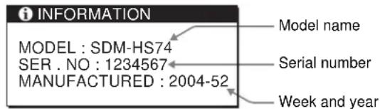
text_image
i INFORMATION MODEL : SDM-HS74 SER . NO : 1234567 MANUFACTURED : 2004-52 Model name Serial number Week and yearIf any problem persists, call your authorized Sony dealer and give the following information:
- Model name: SDM-HS74, SDM-HS94, SDM-HS74P or SDM-HS94P
- Serial number
• Detailed description of the problem - Date of purchase
- Name and specifications of your computer and graphics board
Self-diagnosis function
This monitor is equipped with a self-diagnosis function. If there is a problem with your monitor or computer(s), the screen will go blank and the ⏻ (power) indicator will light up in green. If the ⏻ (power) indicator is lit in orange, the computer is in power saving mode. Try pressing any key on the keyboard or moving the mouse.
text_image
SONY (b) (power) indicatorIf the picture disappears from the screen and the ⏻ (power) indicator is green
1 Turn off the ⏻ (power) switch and disconnect the video signal cables from the monitor.
2 Turn the monitor on by pressing the ⏻ (power) switch.
If all four color bars appear (white, red, green, blue), the monitor is working properly. Reconnect the video signal cables and check the condition of your computer(s).
If the color bars do not appear, there is a potential monitor failure. Inform your authorized Sony dealer of the monitor's condition.
Be sure to note the model name and serial number of your monitor. Also note the make and model of your computer and graphics board.
Specifications
SDM-HS74/SDM-HS74P
LCD panel Panel type: a-Si TFT Active Matrix
Picture size: 17.0 inch
Input signal format RGB operating frequency*
Horizontal: 28 - 80 kHz (analog RGB)
28 - 64 kHz (digital RGB)
Vertical: 48 - 75 Hz (analog RGB)
60 Hz (digital RGB)
Resolution Horizontal: Max.1280 dots
Vertical: Max.1024 lines
Input signal levels Analog RGB video signal
0.7 Vp-p, 75 Ω, positive
SYNC signal
TTL level, 2.2 kΩ,
positive or negative
(Separate horizontal and vertical,
or composite sync)
0.3 Vp-p, 75 Ω, negative
(Sync on green)
Digital RGB (DVI) signal: TMDS
(Single link)
Power requirements 100 - 240 V, 50 - 60 Hz,
Max. 1.0 A
Power consumption Max. 45 W
Operating temperature 5 - 35 °C
Dimensions (width/height/depth)
Display (upright):
LCD panel Panel type: a-Si TFT Active Matrix
Picture size: 19.0 inch
Input signal format RGB operating frequency*
Horizontal: 28–80 kHz (analog RGB)
28 - 64 kHz (digital RGB)
Vertical: 48 - 75 Hz (analog RGB)
60 Hz (digital RGB)
Resolution Horizontal: Max.1280 dots
Vertical: Max.1024 lines
Input signal levels Analog RGB video signal
0.7 Vp-p, 75 Ω, positive
SYNC signal
TTL level, 2.2 kΩ,
positive or negative
(Separate horizontal and vertical,
or composite sync)
0.3 Vp-p, 75 Ω, negative
(Sync on green)
Digital RGB (DVI) signal: TMDS
(Single link)
Power requirements 100 – 240 V, 50 – 60 Hz,
Max. 1.0 A
Power consumption Max. 50 W
Operating temperature 5 – 35 °C
Dimensions (width/height/depth)
Display (upright):
Mass Approx. 6.9 kg (15
lb. 3 ^3 /8 oz.)
Plug & Play DDC2B
Accessories See page 7.
* Recommended horizontal and vertical timing condition
• Horizontal sync width duty should be more than 4.8% of total horizontal time or 0.8 s, whichever is larger.
• Horizontal blanking width should be more than 2.5 μsec.
• Vertical blanking width should be more than 450 μsec.
Design and specifications are subject to change without notice.
TFT LCD Color Computer Display
Mode d'emploi
FR
SDM-HS74
SDM-HS94
SDM-HS74P
SDM-HS94P
Owner's Record
The model and serial numbers are located at the rear of the unit. Record these numbers in the spaces provided below. Refer to them whenever you call upon your dealer regarding this product. Model No. ____ Serial No. ____
WARNING
To prevent fire or shock hazard, do not expose the unit to rain or moisture.
Dangerously high voltages are present inside the unit. Do not open the cabinet. Refer servicing to qualified personnel only.
FCC Notice
This equipment has been tested and found to comply with the limits for a Class B digital device, pursuant to Part 15 of the FCC Rules. These limits are designed to provide reasonable protection against harmful interference in a residential installation. This equipment generates, uses, and can radiate radio frequency energy and, if not installed and used in accordance with the instructions, may cause harmful interference to radio communications. However, there is no guarantee that interference will not occur in a particular installation. If this equipment does cause harmful interference to radio or television reception, which can be determined by turning the equipment off and on, the user is encouraged to try to correct the interference by one or more of the following measures:
– Reorient or relocate the receiving antenna.
– Increase the separation between the equipment and receiver.
- Connect the equipment into an outlet on a circuit different from that to which the receiver is connected.
- Consult the dealer or an experienced radio/TV technician for help. You are cautioned that any changes or modifications not expressly approved in this manual could void your authority to operate this equipment.
IMPORTANTE
If you have any questions about this product, you may call; Sony Customer Information Services Center 1-800-222-7669 or http://www.sony.com/
Declaration of Conformity
Trade Name: SONY
Model: SDM-HS74
SDM-HS94
SDM-HS74P
SDM-HS94P
Responsible Party: Sony Electronics Inc.
Address: 16450 W. Bernardo Dr,
San Diego, CA 92127 U.S.A.
Telephone Number: 858-942-2230
This device complies with part 15 of the FCC rules. Operation is subject to the following two conditions: (1) This device may not cause harmful interference, and (2) this device must accept any interference received, including interference that may cause undesired operation.
NOTICE
This notice is applicable for USA/Canada only.
If shipped to USA/Canada, install only a UL LISTED/CSA
LABELLED power supply cord meeting the following specifications:
SPECIFICATIONS
Plug Type Nema-Plug 5-15p
Cord Type SVT or SJT, minimum 3 - 18 AWG
Length Maximum 15 feet
Rating Minimum 7 A, 125 V
NOTICE
As an ENERGY STAR Partner, Sony Corporation has determined that this product meets the ENERGY STAR guidelines for energy efficiency.
Table des matières
Précautions....4
natural_image
Technical line drawing of a mechanical component with no visible text or symbolsSDM-HS94/SDM-HS94P

natural_image
Technical line drawing of a mechanical component with no visible text or symbolsnatural_image
Illustration of hands holding a tablet with a curved arrow icon on the screen (no text or symbols)Cliquez sur [Utility] → [Windows]/[Win Utility.exc].
Pour Macintosh
Cliquez sur [Utility] → [Mac]/[Mac Utility].
natural_image
Two-panel image showing a striped pattern on the left and a striped pattern on the right, both without any text or symbols.Cliquez sur [Utility] → [Windows]/[Win Utility.exe].
Pour Macintosh
Cliquez sur [Utility] → [Mac]/[Mac Utility].
text_image
INFORMATIONS CABLE NON CONNECTÉ ENTRÉE1 :DV I -DThe model and serial numbers are located at the rear of the unit. Record these numbers in the spaces provided below. Refer to them whenever you call upon your dealer regarding this product. Model No. ____ Serial No. ____
WARNING
To prevent fire or shock hazard, do not expose the unit to rain or moisture.
Dangerously high voltages are present inside the unit. Do not open the cabinet. Refer servicing to qualified personnel only.
FCC Notice
This equipment has been tested and found to comply with the limits for a Class B digital device, pursuant to Part 15 of the FCC Rules. These limits are designed to provide reasonable protection against harmful interference in a residential installation. This equipment generates, uses, and can radiate radio frequency energy and, if not installed and used in accordance with the instructions, may cause harmful interference to radio communications. However, there is no guarantee that interference will not occur in a particular installation. If this equipment does cause harmful interference to radio or television reception, which can be determined by turning the equipment off and on, the user is encouraged to try to correct the interference by one or more of the following measures:
– Reorient or relocate the receiving antenna.
– Increase the separation between the equipment and receiver.
- Connect the equipment into an outlet on a circuit different from that to which the receiver is connected.
- Consult the dealer or an experienced radio/TV technician for help. You are cautioned that any changes or modifications not expressly approved in this manual could void your authority to operate this equipment.
IMPORTANTE
If you have any questions about this product, you may call; Sony Customer Information Services Center 1-800-222-7669 or http://www.sony.com/
Declaration of Conformity
Trade Name: SONY
Model: SDM-HS74
SDM-HS94
SDM-HS74P
SDM-HS94P
Responsible Party: Sony Electronics Inc.
Address: 16450 W. Bernardo Dr,
San Diego, CA 92127 U.S.A.
Telephone Number: 858-942-2230
This device complies with part 15 of the FCC rules. Operation is subject to the following two conditions: (1) This device may not cause harmful interference, and (2) this device must accept any interference received, including interference that may cause undesired operation.
NOTICE
This notice is applicable for USA/Canada only.
If shipped to USA/Canada, install only a UL LISTED/CSA
LABELLED power supply cord meeting the following specifications:
SPECIFICATIONS
Plug Type Nema-Plug 5-15p
Cord Type SVT or SJT, minimum 3 - 18 AWG
Length Maximum 15 feet
Rating Minimum 7 A, 125 V
NOTICE
As an ENERGY STAR Partner, Sony Corporation has determined that this product meets the ENERGY STAR guidelines for energy efficiency.
Inhalt
natural_image
Technical line drawing of a mechanical component with no visible text or symbolsSDM-HS94/SDM-HS94P
natural_image
Technical line drawing of a mechanical component with no visible text or symbolstext_image
Technical diagram of a mechanical or electrical component with numbered parts labeled 8, 9, and 10.text_image
ca. 5° ca. 20°natural_image
Illustration of hands holding a computer monitor with an arrow icon on the screen (no text or symbols)text_image
GAMMA GAMMA 1 GAMMA 2 GAMMA 3 1 2 8 0 1 0 2 4 6 0 Hz xnatural_image
Two-panel image showing a striped pattern on the left and a striped pattern on the right, both without any text or symbols.Horizontal: 28 - 80 kHz
(Analoges RGB)
28 - 64 kHz
(Digitales RGB)
Vertikal: 48 – 75 Hz
(Analoges RGB)
60 Hz (Digitales RGB)
Horizontal: 28 - 80 kHz
(Analoges RGB)
28 - 64 kHz
(Digitales RGB)
Vertical: 48 – 75 Hz (Analoges RGB)
60 Hz (Digitales RGB)
The model and serial numbers are located at the rear of the unit. Record these numbers in the spaces provided below. Refer to them whenever you call upon your dealer regarding this product. Model No. ____ Serial No. ____
WARNING
To prevent fire or shock hazard, do not expose the unit to rain or moisture.
Dangerously high voltages are present inside the unit. Do not open the cabinet. Refer servicing to qualified personnel only.
FCC Notice
This equipment has been tested and found to comply with the limits for a Class B digital device, pursuant to Part 15 of the FCC Rules. These limits are designed to provide reasonable protection against harmful interference in a residential installation. This equipment generates, uses, and can radiate radio frequency energy and, if not installed and used in accordance with the instructions, may cause harmful interference to radio communications. However, there is no guarantee that interference will not occur in a particular installation. If this equipment does cause harmful interference to radio or television reception, which can be determined by turning the equipment off and on, the user is encouraged to try to correct the interference by one or more of the following measures:
– Reorient or relocate the receiving antenna.
– Increase the separation between the equipment and receiver.
- Connect the equipment into an outlet on a circuit different from that to which the receiver is connected.
- Consult the dealer or an experienced radio/TV technician for help. You are cautioned that any changes or modifications not expressly approved in this manual could void your authority to operate this equipment.
IMPORTANTE
If you have any questions about this product, you may call; Sony Customer Information Services Center 1-800-222-7669 or http://www.sony.com/
Declaration of Conformity
Trade Name: SONY
Model: SDM-HS74
SDM-HS94
SDM-HS74P
SDM-HS94P
Responsible Party: Sony Electronics Inc.
Address: 16450 W. Bernardo Dr,
San Diego, CA 92127 U.S.A.
Telephone Number: 858-942-2230
This device complies with part 15 of the FCC rules. Operation is subject to the following two conditions: (1) This device may not cause harmful interference, and (2) this device must accept any interference received, including interference that may cause undesired operation.
NOTICE
This notice is applicable for USA/Canada only.
If shipped to USA/Canada, install only a UL LISTED/CSA
LABELLED power supply cord meeting the following specifications:
SPECIFICATIONS
Plug Type Nema-Plug 5-15p
Cord Type SVT or SJT, minimum 3 - 18 AWG
Length Maximum 15 feet
Rating Minimum 7 A, 125 V
NOTICE
As an ENERGY STAR Partner, Sony Corporation has determined that this product meets the ENERGY STAR guidelines for energy efficiency.
Índice
Precauciones 4
natural_image
Technical line drawing of a mechanical component with no visible text or symbolsSDM-HS94/SDM-HS94P
natural_image
Technical line drawing of a mechanical component with no visible text or symbolsnatural_image
Illustration of hands holding a tablet with a curved arrow icon on the screen (no text or symbols)text_image
GAMMA ■ GAMMA 1 GAMMA 2 GAMMA 3 1280x 1024/60 Hz OK OK EX I END7 NITIDEZ 1 (página
natural_image
Two-panel image showing a striped pattern on the left and a striped pattern on the right, both without any text or symbols.Haga clic en [Utility] → [Windows]/[Win Utility.exe].
Para Macintosh
Haga clic en [Utility] → [Mac]/[Mac Utility].
MANUFACTURED : 2004-52
Nombre del modelo
Número de serie
Horizontal: 28 - 80 kHz
(RVA analógico)
28 - 64 kHz (RVA digital)
(Horizontal y vertical
Horizontal: 28 - 80 kHz
(RVA analógico)
28-64 kHz (RVA digital)
(Horizontal y vertical
The model and serial numbers are located at the rear of the unit. Record these numbers in the spaces provided below. Refer to them whenever you call upon your dealer regarding this product. Model No. ____ Serial No. ____
WARNING
To prevent fire or shock hazard, do not expose the unit to rain or moisture.
Dangerously high voltages are present inside the unit. Do not open the cabinet. Refer servicing to qualified personnel only.
FCC Notice
This equipment has been tested and found to comply with the limits for a Class B digital device, pursuant to Part 15 of the FCC Rules. These limits are designed to provide reasonable protection against harmful interference in a residential installation. This equipment generates, uses, and can radiate radio frequency energy and, if not installed and used in accordance with the instructions, may cause harmful interference to radio communications. However, there is no guarantee that interference will not occur in a particular installation. If this equipment does cause harmful interference to radio or television reception, which can be determined by turning the equipment off and on, the user is encouraged to try to correct the interference by one or more of the following measures:
– Reorient or relocate the receiving antenna.
– Increase the separation between the equipment and receiver.
- Connect the equipment into an outlet on a circuit different from that to which the receiver is connected.
- Consult the dealer or an experienced radio/TV technician for help. You are cautioned that any changes or modifications not expressly approved in this manual could void your authority to operate this equipment.
IMPORTANTE
If you have any questions about this product, you may call; Sony Customer Information Services Center 1-800-222-7669 or http://www.sony.com/
Declaration of Conformity
Trade Name: SONY
Model: SDM-HS74
SDM-HS94
SDM-HS74P
SDM-HS94P
Responsible Party: Sony Electronics Inc.
Address: 16450 W. Bernardo Dr,
San Diego, CA 92127 U.S.A.
Telephone Number: 858-942-2230
This device complies with part 15 of the FCC rules. Operation is subject to the following two conditions: (1) This device may not cause harmful interference, and (2) this device must accept any interference received, including interference that may cause undesired operation.
NOTICE
This notice is applicable for USA/Canada only.
If shipped to USA/Canada, install only a UL LISTED/CSA
LABELLED power supply cord meeting the following specifications:
SPECIFICATIONS
Plug Type Nema-Plug 5-15p
Cord Type SVT or SJT, minimum 3 - 18 AWG
Length Maximum 15 feet
Rating Minimum 7 A, 125 V
NOTICE
As an ENERGY STAR Partner, Sony Corporation has determined that this product meets the ENERGY STAR guidelines for energy efficiency.
Indice
Precauzioni....4
natural_image
Three line drawings of different types of electrical plugs (no text or symbols)da 100 a 120 V CA da 200 a 240 V CA solo 240 V CA
natural_image
Technical line drawing of a mechanical assembly with no visible text or symbolsSDM-HS94/SDM-HS94P

natural_image
Technical line drawing of a mechanical component with no visible text or symbolstext_image
circa 5° circa 20°natural_image
Illustration of hands holding a tablet with a curved arrow icon on the screen (no text or symbols)natural_image
Two-panel image showing a textured surface before and after transformation, with no visible text or symbols.natural_image
Two-panel image showing a striped pattern before and after transformation, with no visible text or symbols.text_image
| : BASSOThe model and serial numbers are located at the rear of the unit. Record these numbers in the spaces provided below. Refer to them whenever you call upon your dealer regarding this product. Model No. ____ Serial No. ____
WARNING
To prevent fire or shock hazard, do not expose the unit to rain or moisture.
Dangerously high voltages are present inside the unit. Do not open the cabinet. Refer servicing to qualified personnel only.
FCC Notice
This equipment has been tested and found to comply with the limits for a Class B digital device, pursuant to Part 15 of the FCC Rules. These limits are designed to provide reasonable protection against harmful interference in a residential installation. This equipment generates, uses, and can radiate radio frequency energy and, if not installed and used in accordance with the instructions, may cause harmful interference to radio communications. However, there is no guarantee that interference will not occur in a particular installation. If this equipment does cause harmful interference to radio or television reception, which can be determined by turning the equipment off and on, the user is encouraged to try to correct the interference by one or more of the following measures:
– Reorient or relocate the receiving antenna.
– Increase the separation between the equipment and receiver.
- Connect the equipment into an outlet on a circuit different from that to which the receiver is connected.
- Consult the dealer or an experienced radio/TV technician for help. You are cautioned that any changes or modifications not expressly approved in this manual could void your authority to operate this equipment.
IMPORTANTE
If you have any questions about this product, you may call; Sony Customer Information Services Center 1-800-222-7669 or http://www.sony.com/
Declaration of Conformity
Trade Name: SONY
Model: SDM-HS74
SDM-HS94
SDM-HS74P
SDM-HS94P
Responsible Party: Sony Electronics Inc.
Address: 16450 W. Bernardo Dr,
San Diego, CA 92127 U.S.A.
Telephone Number: 858-942-2230
This device complies with part 15 of the FCC rules. Operation is subject to the following two conditions: (1) This device may not cause harmful interference, and (2) this device must accept any interference received, including interference that may cause undesired operation.
NOTICE
This notice is applicable for USA/Canada only.
If shipped to USA/Canada, install only a UL LISTED/CSA
LABELLED power supply cord meeting the following specifications:
SPECIFICATIONS
Plug Type Nema-Plug 5-15p
Cord Type SVT or SJT, minimum 3 - 18 AWG
Length Maximum 15 feet
Rating Minimum 7 A, 125 V
NOTICE
As an ENERGY STAR Partner, Sony Corporation has determined that this product meets the ENERGY STAR guidelines for energy efficiency.
Содержание
natural_image
Technical line drawing of a mechanical component with no visible text or symbolsSDM-HS94/SDM-HS94P
natural_image
Technical line drawing of a mechanical component with no visible text or symbolstext_image
Technical diagram of a mechanical or electrical component with numbered parts labeled 8, 9, and 10.natural_image
Illustration of hands holding a tablet with a curved arrow icon on the screen (no text or symbols)text_image
GAMMA GAMMA 1 GAMMA 2 GAMMA 3 1280 1024 60 Hzx OK EX Inatural_image
Two-panel image showing a grid of vertical bars on the left and a striped pattern on the right, with no visible text or symbols.The model and serial numbers are located at the rear of the unit. Record these numbers in the spaces provided below. Refer to them whenever you call upon your dealer regarding this product. Model No. ____ Serial No. ____
WARNING
To prevent fire or shock hazard, do not expose the unit to rain or moisture.
Dangerously high voltages are present inside the unit. Do not open the cabinet. Refer servicing to qualified personnel only.
FCC Notice
This equipment has been tested and found to comply with the limits for a Class B digital device, pursuant to Part 15 of the FCC Rules. These limits are designed to provide reasonable protection against harmful interference in a residential installation. This equipment generates, uses, and can radiate radio frequency energy and, if not installed and used in accordance with the instructions, may cause harmful interference to radio communications. However, there is no guarantee that interference will not occur in a particular installation. If this equipment does cause harmful interference to radio or television reception, which can be determined by turning the equipment off and on, the user is encouraged to try to correct the interference by one or more of the following measures:
– Reorient or relocate the receiving antenna.
– Increase the separation between the equipment and receiver.
- Connect the equipment into an outlet on a circuit different from that to which the receiver is connected.
- Consult the dealer or an experienced radio/TV technician for help. You are cautioned that any changes or modifications not expressly approved in this manual could void your authority to operate this equipment.
IMPORTANTE
If you have any questions about this product, you may call; Sony Customer Information Services Center 1-800-222-7669 or http://www.sony.com/
Declaration of Conformity
Trade Name: SONY
Model: SDM-HS74
SDM-HS94
SDM-HS74P
SDM-HS94P
Responsible Party: Sony Electronics Inc.
Address: 16450 W. Bernardo Dr,
San Diego, CA 92127 U.S.A.
Telephone Number: 858-942-2230
This device complies with part 15 of the FCC rules. Operation is subject to the following two conditions: (1) This device may not cause harmful interference, and (2) this device must accept any interference received, including interference that may cause undesired operation.
NOTICE
This notice is applicable for USA/Canada only.
If shipped to USA/Canada, install only a UL LISTED/CSA
LABELLED power supply cord meeting the following specifications:
SPECIFICATIONS
Plug Type Nema-Plug 5-15p
Cord Type SVT or SJT, minimum 3 - 18 AWG
Length Maximum 15 feet
Rating Minimum 7 A, 125 V
NOTICE
As an ENERGY STAR Partner, Sony Corporation has determined that this product meets the ENERGY STAR guidelines for energy efficiency.
natural_image
Technical line drawing of a mechanical component with no visible text or symbolsSDM-HS94/SDM-HS94P
natural_image
Technical line drawing of a mechanical component with no visible text or symbols7 Bakre panel (sid. 8)
natural_image
Illustration of hands holding a tablet with a curved arrow icon on the screen (no text or symbols)text_image
Test Sample Test → Test Sample Testnatural_image
Two-panel image showing a striped pattern on the left and a striped pattern on the right, both without any text or symbols.text_image
INFORMATION KABEL EJ ANSLUTEN INSIGNAL1:DVI-DDigital RGB-signal (DVI):
TMDS (Enkel länk)
Digital RGB-signal (DVI):
TMDS (Enkel länk)
The model and serial numbers are located at the rear of the unit. Record these numbers in the spaces provided below. Refer to them whenever you call upon your dealer regarding this product. Model No. ____ Serial No. ____
WARNING
To prevent fire or shock hazard, do not expose the unit to rain or moisture.
Dangerously high voltages are present inside the unit. Do not open the cabinet. Refer servicing to qualified personnel only.
FCC Notice
This equipment has been tested and found to comply with the limits for a Class B digital device, pursuant to Part 15 of the FCC Rules. These limits are designed to provide reasonable protection against harmful interference in a residential installation. This equipment generates, uses, and can radiate radio frequency energy and, if not installed and used in accordance with the instructions, may cause harmful interference to radio communications. However, there is no guarantee that interference will not occur in a particular installation. If this equipment does cause harmful interference to radio or television reception, which can be determined by turning the equipment off and on, the user is encouraged to try to correct the interference by one or more of the following measures:
– Reorient or relocate the receiving antenna.
– Increase the separation between the equipment and receiver.
- Connect the equipment into an outlet on a circuit different from that to which the receiver is connected.
- Consult the dealer or an experienced radio/TV technician for help. You are cautioned that any changes or modifications not expressly approved in this manual could void your authority to operate this equipment.
IMPORTANTE
If you have any questions about this product, you may call; Sony Customer Information Services Center 1-800-222-7669 or http://www.sony.com/
Declaration of Conformity
Trade Name: SONY
Model: SDM-HS74
SDM-HS94
SDM-HS74P
SDM-HS94P
Responsible Party: Sony Electronics Inc.
Address: 16450 W. Bernardo Dr,
San Diego, CA 92127 U.S.A.
Telephone Number: 858-942-2230
This device complies with part 15 of the FCC rules. Operation is subject to the following two conditions: (1) This device may not cause harmful interference, and (2) this device must accept any interference received, including interference that may cause undesired operation.
NOTICE
This notice is applicable for USA/Canada only.
If shipped to USA/Canada, install only a UL LISTED/CSA
LABELLED power supply cord meeting the following specifications:
SPECIFICATIONS
Plug Type Nema-Plug 5-15p
Cord Type SVT or SJT, minimum 3 - 18 AWG
Length Maximum 15 feet
Rating Minimum 7 A, 125 V
NOTICE
As an ENERGY STAR Partner, Sony Corporation has determined that this product meets the ENERGY STAR guidelines for energy efficiency.
Inhoudsopgave
natural_image
Technical line drawing of a mechanical component with no visible text or symbolsSDM-HS94/SDM-HS94P
natural_image
Technical line drawing of a mechanical component with no visible text or symbolstext_image
ca. 5° ca. 20°natural_image
Illustration of hands holding a tablet with a curved arrow on the screen (no text or symbols)text_image
GAMMA GAMMA 1 GAMMA 2 GAMMA 3 1 2 8 0 1 0 2 4 6 0 Hz x DO → EX Itext_image
RESET OK ANNULEREN 1280 1024 60 Hz x 10 + OK EX I timeKlik op [Utility] → [Windows]/[Win Utility.exe].
Voor Macintosh
Klik op [Utility] → [Mac]/[Mac Utility].
text_image
Red Fiber Silica Fibernatural_image
Two-panel image showing a striped pattern on the left and a grayscale striped pattern on the right, both without any text or symbols.Klik op [Utility] → [Windows]/[Win Utility.exe].
Voor Macintosh
Klik op [Utility] → [Mac]/[Mac Utility].
text_image
INFORMATIE BUI TEN BERE IK INGANG1:DVI-D xxxx.xkHz/xxxxztext_image
INFORMATIE GEEN INPUT S I GNAAL INGANG1:D VI-D GA NAAR STROOMSPAARGA NAAR STROOMSPAAR
The model and serial numbers are located at the rear of the unit. Record these numbers in the spaces provided below. Refer to them whenever you call upon your dealer regarding this product. Model No. ____ Serial No. ____
WARNING
To prevent fire or shock hazard, do not expose the unit to rain or moisture.
Dangerously high voltages are present inside the unit. Do not open the cabinet. Refer servicing to qualified personnel only.
FCC Notice
This equipment has been tested and found to comply with the limits for a Class B digital device, pursuant to Part 15 of the FCC Rules. These limits are designed to provide reasonable protection against harmful interference in a residential installation. This equipment generates, uses, and can radiate radio frequency energy and, if not installed and used in accordance with the instructions, may cause harmful interference to radio communications. However, there is no guarantee that interference will not occur in a particular installation. If this equipment does cause harmful interference to radio or television reception, which can be determined by turning the equipment off and on, the user is encouraged to try to correct the interference by one or more of the following measures:
– Reorient or relocate the receiving antenna.
– Increase the separation between the equipment and receiver.
- Connect the equipment into an outlet on a circuit different from that to which the receiver is connected.
- Consult the dealer or an experienced radio/TV technician for help.
You are cautioned that any changes or modifications not expressly approved in this manual could void your authority to operate this equipment.
IMPORTANTE
If you have any questions about this product, you may call; Sony Customer Information Services Center 1-800-222-7669 or http://www.sony.com/
Declaration of Conformity
Trade Name: SONY
Model: SDM-HS74
SDM-HS94
SDM-HS74P
SDM-HS94P
Responsible Party: Sony Electronics Inc.
Address: 16450 W. Bernardo Dr,
San Diego, CA 92127 U.S.A.
Telephone Number: 858-942-2230
This device complies with part 15 of the FCC rules. Operation is subject to the following two conditions: (1) This device may not cause harmful interference, and (2) this device must accept any interference received, including interference that may cause undesired operation.
NOTICE
This notice is applicable for USA/Canada only. If shipped to USA/Canada, install only a UL LISTED/CSA LABELLED power supply cord meeting the following specifications:
SPECIFICATIONS
Plug Type Nema-Plug 5-15p
Cord Type SVT or SJT, minimum 3 · 18 AWG
Length Maximum 15 feet
Rating Minimum 7 A, 125 V
NOTICE
As an ENERGY STAR Partner, Sony Corporation has determined that this product meets the ENERGY STAR guidelines for energy efficiency.
目录
使用前须知注意事项 4
识别部件和控制钮 5
安装 7
natural_image
Line drawings of three different types of electrical plugs (no text or symbols present)natural_image
Technical line drawing of a mechanical assembly with no visible text or symbolsSDM-HS94/SDM-HS94P
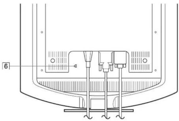
natural_image
Technical line drawing of a mechanical component with no visible text or symbolsnatural_image
Illustration of hands holding a tablet with a curved arrow icon on the screen (no text or symbols)若要舒适地使用显示器
natural_image
Two-panel image showing a textured surface before and after transformation, with no visible text or symbols.8 按 0K 按钮。
返回到屏幕效果。
natural_image
Two-panel image showing a striped pattern on the left and a striped pattern on the right, with no visible text or symbols.The model and serial numbers are located at the rear of the unit. Record these numbers in the spaces provided below. Refer to them whenever you call upon your dealer regarding this product. Model No. ____ Serial No. ____
WARNING
To prevent fire or shock hazard, do not expose the unit to rain or moisture.
Dangerously high voltages are present inside the unit. Do not open the cabinet. Refer servicing to qualified personnel only.
FCC Notice
This equipment has been tested and found to comply with the limits for a Class B digital device, pursuant to Part 15 of the FCC Rules. These limits are designed to provide reasonable protection against harmful interference in a residential installation. This equipment generates, uses, and can radiate radio frequency energy and, if not installed and used in accordance with the instructions, may cause harmful interference to radio communications. However, there is no guarantee that interference will not occur in a particular installation. If this equipment does cause harmful interference to radio or television reception, which can be determined by turning the equipment off and on, the user is encouraged to try to correct the interference by one or more of the following measures:
– Reorient or relocate the receiving antenna.
– Increase the separation between the equipment and receiver.
- Connect the equipment into an outlet on a circuit different from that to which the receiver is connected.
- Consult the dealer or an experienced radio/TV technician for help. You are cautioned that any changes or modifications not expressly approved in this manual could void your authority to operate this equipment.
IMPORTANTE
If you have any questions about this product, you may call; Sony Customer Information Services Center 1-800-222-7669 or http://www.sony.com/
Declaration of Conformity
Trade Name: SONY
Model: SDM-HS74
SDM-HS94
SDM-HS74P
SDM-HS94P
Responsible Party: Sony Electronics Inc.
Address: 16450 W. Bernardo Dr,
San Diego, CA 92127 U.S.A.
Telephone Number: 858-942-2230
This device complies with part 15 of the FCC rules. Operation is subject to the following two conditions: (1) This device may not cause harmful interference, and (2) this device must accept any interference received, including interference that may cause undesired operation.
NOTICE
This notice is applicable for USA/Canada only.
If shipped to USA/Canada, install only a UL LISTED/CSA
LABELLED power supply cord meeting the following specifications:
SPECIFICATIONS
Plug Type Nema-Plug 5-15p
Cord Type SVT or SJT, minimum 3 × 18 AWG
Length Maximum 15 feet
Rating Minimum 7 A, 125 V
NOTICE
As an ENERGY STAR Partner, Sony Corporation has determined that this product meets the ENERGY STAR guidelines for energy efficiency.
Obsah
natural_image
Technical line drawing of a mechanical assembly with no visible text or symbolsSDM-HS94/SDM-HS94P
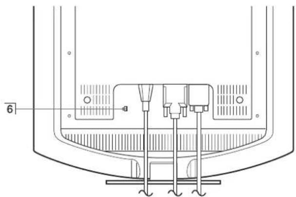
natural_image
Technical line drawing of a mechanical component with no visible text or symbolsnatural_image
Illustration of hands holding a tablet with a curved arrow icon on the screen (no text or symbols)HIGH → MIDDLE → LOW → USER → HIGH ...
text_image
GAMMA GAMMA 1 GAMMA 2 GAMMA 3 1 2 8 0 1 0 2 4 6 0 Hz x7 SHARPNESS (strana 14)
natural_image
Two-panel image showing a textured surface before and after transformation, with no visible text or symbols.natural_image
Two-panel image showing a striped pattern on the left and a striped pattern on the right, with no visible text or symbols.text_image
|:○□ ↓ ↑ → |:○ : LOWtext_image
INFORMATION CABLE DISCONNECTED INPUT1:DVI-DThe model and serial numbers are located at the rear of the unit. Record these numbers in the spaces provided below. Refer to them whenever you call upon your dealer regarding this product. Model No. ____ Serial No. ____
WARNING
To prevent fire or shock hazard, do not expose the unit to rain or moisture.
Dangerously high voltages are present inside the unit. Do not open the cabinet. Refer servicing to qualified personnel only.
FCC Notice
This equipment has been tested and found to comply with the limits for a Class B digital device, pursuant to Part 15 of the FCC Rules. These limits are designed to provide reasonable protection against harmful interference in a residential installation. This equipment generates, uses, and can radiate radio frequency energy and, if not installed and used in accordance with the instructions, may cause harmful interference to radio communications. However, there is no guarantee that interference will not occur in a particular installation. If this equipment does cause harmful interference to radio or television reception, which can be determined by turning the equipment off and on, the user is encouraged to try to correct the interference by one or more of the following measures:
– Reorient or relocate the receiving antenna.
– Increase the separation between the equipment and receiver.
- Connect the equipment into an outlet on a circuit different from that to which the receiver is connected.
- Consult the dealer or an experienced radio/TV technician for help. You are cautioned that any changes or modifications not expressly approved in this manual could void your authority to operate this equipment.
IMPORTANTE
If you have any questions about this product, you may call; Sony Customer Information Services Center 1-800-222-7669 or http://www.sony.com/
Declaration of Conformity
Trade Name: SONY
Model: SDM-HS74
SDM-HS94
SDM-HS74P
SDM-HS94P
Responsible Party: Sony Electronics Inc.
Address: 16450 W. Bernardo Dr,
San Diego, CA 92127 U.S.A.
Telephone Number: 858-942-2230
This device complies with part 15 of the FCC rules. Operation is subject to the following two conditions: (1) This device may not cause harmful interference, and (2) this device must accept any interference received, including interference that may cause undesired operation.
NOTICE
This notice is applicable for USA/Canada only.
If shipped to USA/Canada, install only a UL LISTED/CSA
LABELLED power supply cord meeting the following specifications:
SPECIFICATIONS
Plug Type Nema-Plug 5-15p
Cord Type SVT or SJT, minimum 3 × 18 AWG
Length Maximum 15 feet
Rating Minimum 7 A, 125 V
NOTICE
As an ENERGY STAR Partner, Sony Corporation has determined that this product meets the ENERGY STAR guidelines for energy efficiency.
Kazalo
Pozor 4
Deli monitorja in elementi za nastavljanje. 5
Nastavitev....7
Nastavitev 1: Priključite monitor na vaš računalnik ..... 7
natural_image
Three line drawings of different types of electrical plugs (no text or symbols)natural_image
Technical line drawing of a mechanical assembly with no visible text or symbolsSDM-HS94/SDM-HS94P
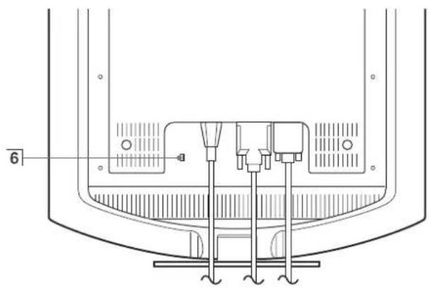
natural_image
Technical line drawing of a mechanical component with no visible text or symbols① ⏻ (Napajalno) stikalo in indikator (strani 9, 16, 20)
text_image
Pribl. 5° Pribl. 20°Primate spodnji del LCD zaslona in nato nastavite naklon.
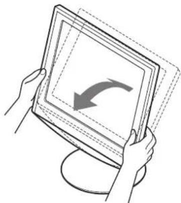
natural_image
Illustration of hands holding a tablet with a curved arrow icon on the screen (no text or symbols)HIGH → MIDDLE → LOW → USER → HIGH ...
text_image
GAMMA GAMMA 1 GAMMA 2 GAMMA 3 1280x 1024/60 Hz7 SHARPNESS
(stran 14)
Izberite meni SHARPNESS, da nastavite ostrino robov slik.
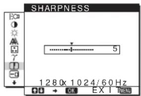
text_image
SHARPNESS 1280x 1024/60 Hz8 MENU POSITION
(stran 14)
Kliknite [Utility] → [Windows]/[Win Utility.exe].
Za Macintosh
Kliknite [Utility] → [Mac]/[Mac Utility].
4 Pritisnite tipko MENU.
Na zaslonu se prikaže glavni meni.
5 Pritisnite tipki ↓/↑ za izbiro ⚠ (SCREEN) in pritisnite tipko OK.
Na zaslonu se prikaže meni SCREEN.
6 Pritisnite tipki ↓/↑, da izberete PHASE in pritisnite tipko OK.
Na zaslonu se prikaže meni PHASE.
7 Pritisnite tipki ↓/↑, dokler niso vodoravni pasovi minimalni.
Nastavljajte toliko časa, da so vodoravni pasovi minimalni.
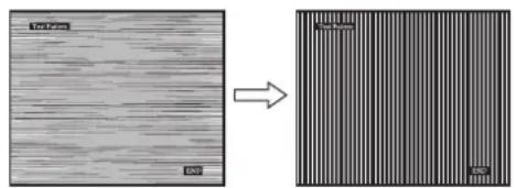
natural_image
Two-panel image showing a textured surface before and after transformation, with no visible text or symbols.8 Pritisnite tipko OK.
Vrnite se v meni SCREEN.
natural_image
Two-panel image showing a striped pattern before and after transformation, with no visible text or symbols.Kliknite [Utility] → [Windows]/[Win Utility.exe].
Za Macintosh
Kliknite [Utility] → [Mac]/[Mac Utility].
4 Pritisnite tipko MENU.
Na zaslonu se prikaže glavni meni.
5 Pritisnite tipki ↓/↑ za izbiro ⚠ (SCREEN) in pritisnite tipko OK.
Na zaslonu se prikaže meni SCREEN.
6 Pritisnite tipki ↓/↑, da izberete H CENTER ali V CENTER in pritisnite tipko OK.
Na zaslonu se pojavi meni H CENTER ali meni V CENTER.
text_image
INFORMATION CABLE DI SCONNECTED INPUT1:DVI-DVelikost slike: 19,0
Pribl. 480 × 440 × 260 mm
(19× 17^3 / 8× 10^1 / 4 palcev)
lb. 3 ^3 /8 oz.)
Masa Pribl. 6,9 kg (15
Plug & Play DDC2B
Dodatki Glej stran 7.
The model and serial numbers are located at the rear of the unit. Record these numbers in the spaces provided below. Refer to them whenever you call upon your dealer regarding this product. Model No. ____ Serial No. ____
WARNING
To prevent fire or shock hazard, do not expose the unit to rain or moisture.
Dangerously high voltages are present inside the unit. Do not open the cabinet. Refer servicing to qualified personnel only.
FCC Notice
This equipment has been tested and found to comply with the limits for a Class B digital device, pursuant to Part 15 of the FCC Rules. These limits are designed to provide reasonable protection against harmful interference in a residential installation. This equipment generates, uses, and can radiate radio frequency energy and, if not installed and used in accordance with the instructions, may cause harmful interference to radio communications. However, there is no guarantee that interference will not occur in a particular installation. If this equipment does cause harmful interference to radio or television reception, which can be determined by turning the equipment off and on, the user is encouraged to try to correct the interference by one or more of the following measures:
– Reorient or relocate the receiving antenna.
– Increase the separation between the equipment and receiver.
- Connect the equipment into an outlet on a circuit different from that to which the receiver is connected.
- Consult the dealer or an experienced radio/TV technician for help. You are cautioned that any changes or modifications not expressly approved in this manual could void your authority to operate this equipment.
IMPORTANTE
If you have any questions about this product, you may call; Sony Customer Information Services Center 1-800-222-7669 or http://www.sony.com/
Declaration of Conformity
Trade Name: SONY
Model: SDM-HS74
SDM-HS94
SDM-HS74P
SDM-HS94P
Responsible Party: Sony Electronics Inc.
Address: 16450 W. Bernardo Dr,
San Diego, CA 92127 U.S.A.
Telephone Number: 858-942-2230
This device complies with part 15 of the FCC rules. Operation is subject to the following two conditions: (1) This device may not cause harmful interference, and (2) this device must accept any interference received, including interference that may cause undesired operation.
NOTICE
This notice is applicable for USA/Canada only.
If shipped to USA/Canada, install only a UL LISTED/CSA
LABELLED power supply cord meeting the following specifications:
SPECIFICATIONS
Plug Type Nema-Plug 5-15p
Cord Type SVT or SJT, minimum 3 × 18 AWG
Length Maximum 15 feet
Rating Minimum 7 A, 125 V
NOTICE
As an ENERGY STAR Partner, Sony Corporation has determined that this product meets the ENERGY STAR guidelines for energy efficiency.
Spis treści
(INPUT SENSING)....15
ZERO (BOLEC OCHRONNY)
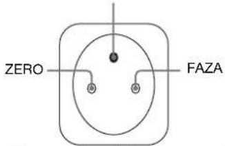
text_image
ZERO FAZAnatural_image
Technical line drawing of a mechanical component with no visible text or symbolsSDM-HS94/SDM-HS94P
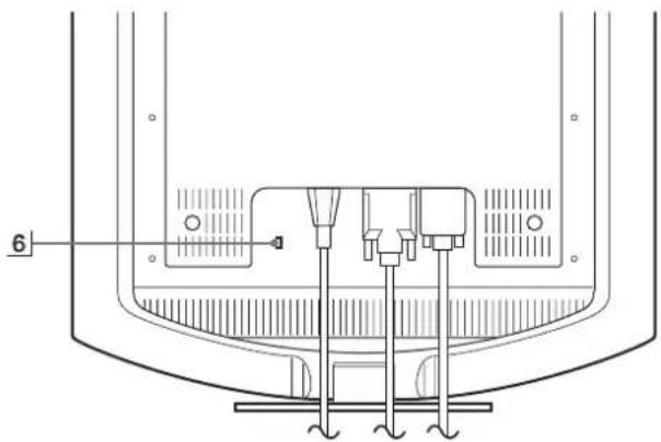
natural_image
Technical line drawing of a mechanical component with no visible text or symbols1 Przycisk i kontrolka zasilania ⏻ (str. 9, 17, 21)
natural_image
Illustration of hands holding a tablet with an arrow indicating rotation (no text or symbols)HIGH → MIDDLE → LOW → USER → HIGH ...
text_image
GAMMA ■GAMMA 1 GAMMA 2 GAMMA 3 1 2 8 0 1 0 2 4 6 0 Hz xtext_image
SHARPNESS 1280 1024 60 Hz x 00 → EX EX Inatural_image
Two-panel image showing a striped pattern before and after transformation, with no visible text or symbols.text_image
|○□ ↓ → |○□ : LOWtext_image
INFORMATION CABLE DISCONNECTED INPUT1:DVI-DThe model and serial numbers are located at the rear of the unit. Record these numbers in the spaces provided below. Refer to them whenever you call upon your dealer regarding this product. Model No. ____ Serial No. ____
WARNING
To prevent fire or shock hazard, do not expose the unit to rain or moisture.
Dangerously high voltages are present inside the unit. Do not open the cabinet. Refer servicing to qualified personnel only.
FCC Notice
This equipment has been tested and found to comply with the limits for a Class B digital device, pursuant to Part 15 of the FCC Rules. These limits are designed to provide reasonable protection against harmful interference in a residential installation. This equipment generates, uses, and can radiate radio frequency energy and, if not installed and used in accordance with the instructions, may cause harmful interference to radio communications. However, there is no guarantee that interference will not occur in a particular installation. If this equipment does cause harmful interference to radio or television reception, which can be determined by turning the equipment off and on, the user is encouraged to try to correct the interference by one or more of the following measures:
– Reorient or relocate the receiving antenna.
– Increase the separation between the equipment and receiver.
- Connect the equipment into an outlet on a circuit different from that to which the receiver is connected.
- Consult the dealer or an experienced radio/TV technician for help. You are cautioned that any changes or modifications not expressly approved in this manual could void your authority to operate this equipment.
IMPORTANTE
If you have any questions about this product, you may call; Sony Customer Information Services Center 1-800-222-7669 or http://www.sony.com/
Declaration of Conformity
Trade Name: SONY
Model: SDM-HS74
SDM-HS94
SDM-HS74P
SDM-HS94P
Responsible Party: Sony Electronics Inc.
Address: 16450 W. Bernardo Dr,
San Diego, CA 92127 U.S.A.
Telephone Number: 858-942-2230
This device complies with part 15 of the FCC rules. Operation is subject to the following two conditions: (1) This device may not cause harmful interference, and (2) this device must accept any interference received, including interference that may cause undesired operation.
NOTICE
This notice is applicable for USA/Canada only.
If shipped to USA/Canada, install only a UL LISTED/CSA
LABELLED power supply cord meeting the following specifications:
SPECIFICATIONS
Plug Type Nema-Plug 5-15p
Cord Type SVT or SJT, minimum 3 × 18 AWG
Length Maximum 15 feet
Rating Minimum 7 A, 125 V
NOTICE
As an ENERGY STAR Partner, Sony Corporation has determined that this product meets the ENERGY STAR guidelines for energy efficiency.
Tartalomjegyzék
Óvintézkedések 4
natural_image
Three line drawings of different types of electrical plugs (no text or symbols)natural_image
Technical line drawing of a mechanical assembly with no visible text or symbolsSDM-HS94/SDM-HS94P

natural_image
Technical line drawing of a mechanical component with no visible text or symbolsnatural_image
Illustration of hands holding a tablet with a curved arrow icon on the screen (no text or symbols)HIGH → MIDDLE → LOW → USER → HIGH ...
text_image
GAMMA ■GAMMA 1 GAMMA 2 GAMMA 3 1 2 8 0 1 0 2 4 6 0 Hz x OK EX I TEAD7 SHARPNESS
(15. oldal)
natural_image
Two-panel image showing a textured surface before and after transformation, with no visible text or symbols.natural_image
Two-panel image showing a striped pattern before and after transformation, with no visible text or symbols.text_image
|○□ ↓ → |○□ : LOWtext_image
INFORMATION CABLE D I SCONNECTED INPUT1:DVI-DThe model and serial numbers are located at the rear of the unit. Record these numbers in the spaces provided below. Refer to them whenever you call upon your dealer regarding this product. Model No. ____ Serial No. ____
WARNING
To prevent fire or shock hazard, do not expose the unit to rain or moisture.
Dangerously high voltages are present inside the unit. Do not open the cabinet. Refer servicing to qualified personnel only.
FCC Notice
This equipment has been tested and found to comply with the limits for a Class B digital device, pursuant to Part 15 of the FCC Rules. These limits are designed to provide reasonable protection against harmful interference in a residential installation. This equipment generates, uses, and can radiate radio frequency energy and, if not installed and used in accordance with the instructions, may cause harmful interference to radio communications. However, there is no guarantee that interference will not occur in a particular installation. If this equipment does cause harmful interference to radio or television reception, which can be determined by turning the equipment off and on, the user is encouraged to try to correct the interference by one or more of the following measures:
– Reorient or relocate the receiving antenna.
– Increase the separation between the equipment and receiver.
- Connect the equipment into an outlet on a circuit different from that to which the receiver is connected.
- Consult the dealer or an experienced radio/TV technician for help. You are cautioned that any changes or modifications not expressly approved in this manual could void your authority to operate this equipment.
IMPORTANTE
| If you have any questions about this product, you may call; Sony Customer Information Services Center 1-800-222-7669 or http://www.sony.com/ |
Declaration of Conformity
Trade Name: SONY
Model: SDM-HS74
SDM-HS94
SDM-HS74P
SDM-HS94P
Responsible Party: Sony Electronics Inc.
Address: 16450 W. Bernardo Dr.
San Diego, CA 92127 U.S.A.
Telephone Number: 858-942-2230
This device complies with part 15 of the FCC rules. Operation is subject to the following two conditions: (1) This device may not cause harmful interference, and (2) this device must accept any interference received, including interference that may cause undesired operation.
NOTICE
This notice is applicable for USA/Canada only.
If shipped to USA/Canada, install only a UL LISTED/CSA
LABELLED power supply cord meeting the following specifications:
SPECIFICATIONS
Plug Type Nema-Plug 5-15p
Cord Type SVT or SJT, minimum 3 . 18 AWG
Length Maximum 15 feet
Rating Minimum 7 A, 125 V
NOTICE
As an ENERGY STAR Partner, Sony Corporation has determined that this product meets the ENERGY STAR guidelines for energy efficiency.
İçindekiler
Uyarılar....4
natural_image
Three line drawings of different types of electrical plugs (no text or symbols)natural_image
Technical line drawing of a mechanical component with no visible text or symbolsSDM-HS94/SDM-HS94P
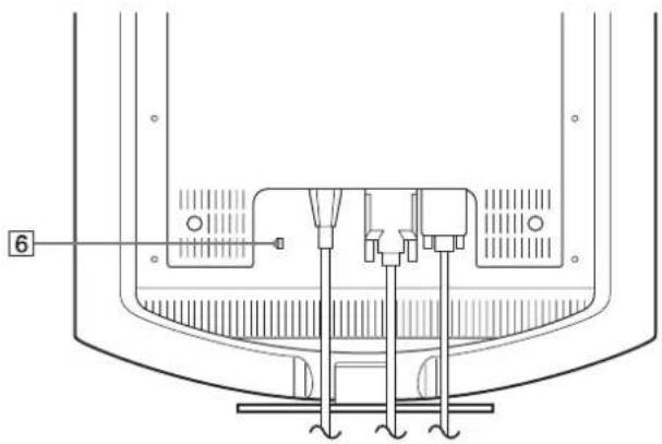
natural_image
Technical line drawing of a mechanical component with no visible text or symbolsnatural_image
Illustration of hands holding a tablet with a curved arrow on the screen (no text or symbols)HIGH → MIDDLE → LOW → USER → HIGH ...
text_image
GAMMA ■GAMMA 1 GAMMA 2 GAMMA 3 1 2 8 0 1 0 2 4 6 0 Hz x OK → OK EX I NEW7SHARPNESS (sayfa 14)
text_image
SHARPNESS 5 1 2 8 0 1 0 2 4 6 0 Hz x OK EX I NEW8 MENU POSITION (sayfa 14)
text_image
Diagram showing a textured surface before and after transformation, with labeled regions and scale indicators.natural_image
Two-panel image showing a striped pattern on the left and a striped pattern on the right, both without any text or symbols.Dikey frekans: 48–75 Hz