
AV28X28EU - Television JVC - Free user manual and instructions
Find the device manual for free AV28X28EU JVC in PDF.
| Product Type | Colour Television |
| Brand | JVC |
| Model | AV28X28EU |
| Screen Size (diagonal) | 66 cm (28 inches) |
| Dimensions (W × H × D) | 780 × 509 × 499 mm |
| Weight | 40.2 kg |
| Power Supply | 220 – 240 V AC, 50 Hz |
| Power Consumption | Max. 178 W, average 125 W, standby 2.6 W |
| TV Systems | CCIR B/G, I, D/K, L ; PAL, SECAM ; NTSC 3.58/4.43 on EXT inputs |
| Main Functions | T-V LINK, teletext FLOF/TOP/WST, multi-mode zoom, Hyper Sound, BBE, digital noise reduction, parental lock, sleep timer |
| Inputs / Outputs | 4 SCART sockets (EXT-1 to EXT-3), EXT-4 with RCA and S-Video, RCA audio output, 3.5 mm headphone jack |
| Audio Output | 7.5 W + 7.5 W |
| Speakers | 2 oval (13 cm × 6.5 cm) with magnetic shielding |
| Care and Cleaning | Wipe the screen with a soft dry cloth. Never use cleaning products or detergents. Do not rub. |
| Safety | Do not obstruct ventilation openings. Do not expose to rain or moisture. Unplug if not used for extended periods. Do not open the cabinet. |
| Repairability | Do not attempt repairs yourself. Entrust exclusively to a qualified technician. |
| General Information | User manual available in several languages. |
Frequently Asked Questions - AV28X28EU JVC
User questions about AV28X28EU JVC
0 question about this device. Answer the ones you know or ask your own.
Ask a new question about this device
Download the instructions for your Television in PDF format for free! Find your manual AV28X28EU - JVC and take your electronic device back in hand. On this page are published all the documents necessary for the use of your device. AV28X28EU by JVC.
USER MANUAL AV28X28EU JVC
MANUEL D'INSTRUCTIONS
GEBRUIKSAANWIJZING
Thank you for buying this JVC colour television.
To make sure you understand how to use your new TV, please read this manual thoroughly before you begin.
WARNING: TO PREVENT FIRE OR SHOCK HAZARD, DO NOT EXPOSE THIS APPLIANCE TO RAIN OR MOISTURE.
CAUTION:
- Operate only from the power source specified (AC 220 – 240 V, 50 Hz) on the unit.
- Avoid damaging the AC plug and power cord.
- When you are not using this unit for a long period of time, it is recommended that you disconnect the power cord from the main outlet.
- The main power button on the TV does not fully isolate the TV from the AC supply. If you are not going to use this TV for a long period of time, be sure to disconnect the AC plug from the AC socket.
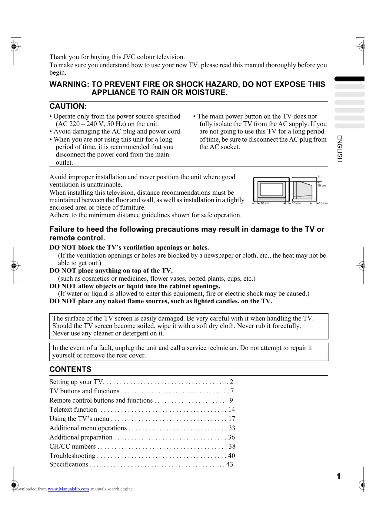
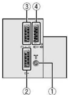
Avoid improper installation and never position the unit where good ventilation is unattainable.
When installing this television, distance recommendations must be maintained between the floor and wall, as well as installation in a tightly enclosed area or piece of furniture.
Adhere to the minimum distance guidelines shown for safe operation.
Failure to heed the following precautions may result in damage to the TV or remote control.
DO NOT block the TV's ventilation openings or holes.
(If the ventilation openings or holes are blocked by a newspaper or cloth, etc., the heat may not be able to get out.)
DO NOT place anything on top of the TV.
(such as cosmetics or medicines, flower vases, potted plants, cups, etc.)
DO NOT allow objects or liquid into the cabinet openings.
(If water or liquid is allowed to enter this equipment, fire or electric shock may be caused.)
DO NOT place any naked flame sources, such as lighted candles, on the TV.
The surface of the TV screen is easily damaged. Be very careful with it when handling the TV. Should the TV screen become soiled, wipe it with a soft dry cloth. Never rub it forcefully. Never use any cleaner or detergent on it.
In the event of a fault, unplug the unit and call a service technician. Do not attempt to repair it yourself or remove the rear cover.
CONTENTS
Setting up your TV....2
TV buttons and functions 7
Remote control buttons and functions 9
Teletext function 14
Using the TV's menu 17
Additional menu operations 33
Additional preparation 36
CH/CC numbers 38
Troubleshooting 40
Specifications 43
Setting up your TV
Caution
- Turn off all the equipment including the TV before connecting anything.
Connecting the aerial and VCR
• The connecting cables are not provided.
- For further details, refer to the manuals provided with the devices to be connected.
■ If connecting a VCR, follow A→ B → C.
■ If not connecting a VCR, follow①①
To operate T-V LINK functions, a T-V LINK compatible VCR must be connected to the EXT-2 terminal on the TV. For details about T-V LINK functions, see “T-V LINK FUNCTIONS” on page 5.
- A video can be viewed from the VCR without performing ©. For details, refer to your VCR instruction manual.
- To connect additional external devices, please see “Additional preparation” on page 36.
- To connect speakers and amplifier, please see “Connecting Speakers/Amplifier (Excluding AV28CH1EU)” on page 37.
- When a decoder is connected to a T-V LINK compatible VCR, set the DECODER (EXT-2) function to ON. For details, see “Using the DECODER (EXT-2) function” on page 35. Otherwise, you will not be able to view scrambled channels.

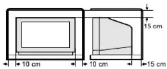
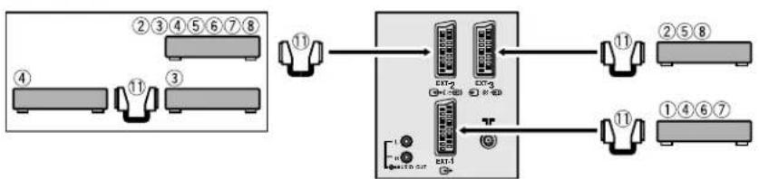
■ Rear Panel
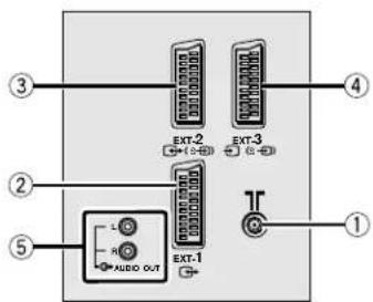
①Aerial socket (2)
②EXT-1 terminal (2, 22, 36)
③EXT-2 terminal (2, 5, 22, 36)
④EXT-3 terminal (22, 36)
⑤AUDIO OUT terminal (Excluding AV28CH1EU) (37)
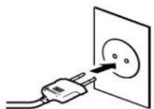
Connecting the power cord to the AC outlet
Caution
- Operate only from the power source specified (AC 220 – 240 V, 50 Hz) on the unit.
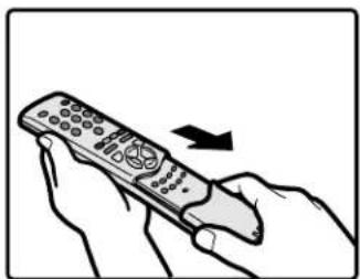
Putting the batteries into the Remote control
Use two AAA/R03 dry cell batteries. Insert the batteries from the end, making sure the and polarities are correct.
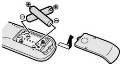
- Follow the warnings printed on the batteries.
- Battery life is about six months to one year, depending on your frequency of use.
- The batteries we supply are only for setting up and testing your TV, please replace them as soon as necessary.
- If the remote control does not work properly, replace the batteries.
Initial settings
When the TV is first turned on, it enters the initial setting mode, and the JVC logo is displayed. Follow the instructions on the on-screen display to make the initial settings.
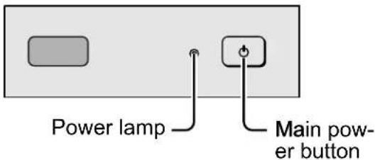
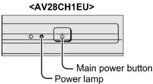
1 Press the Main power button on the TV
The Power lamp lights red (for power on), then green (for TV on) and the JVC logo is displayed.
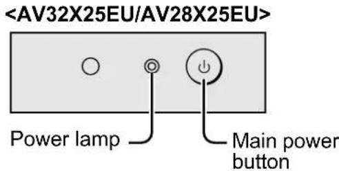
- If the power lamp stays red and does not change to green: Your TV is in the standby mode. Press the ⏻/l (Standby) button on the remote control to turn your TV on.
- The JVC logo does not appear when your TV has been turned on once. In this case, use the “LANGUAGE” and “AUTO PROGRAM” functions to make the initial settings. For details, see “INSTALL” on page 27.
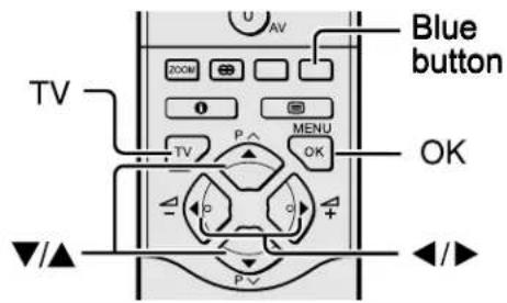
2 Press the OK button
The LANGUAGE menu appears.
3 Press the ◀◀▶ and ▼/▲ buttons to choose ENGLISH. Then press the OK button
English is set for the on-screen display description. The COUNTRY menu appears as a sub-menu of the AUTO PROGRAM function.
There are two COUNTRY menus. Pressing the yellow button changes the COUNTRY menu as follows:
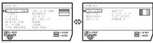
4 Press the ◀◀▶ and ▼/▲ buttons to choose the country where you are now located
5 Press the blue button to start the AUTO PROGRAM function
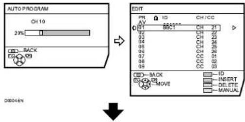
The AUTO PROGRAM menu appears and received TV channels are automatically registered in the Programme numbers (PR).
- To cancel the AUTO PROGRAM function: Press the TV button.
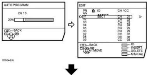
After the TV channels have been registered in the Programme numbers (PR), the EDIT menu appears
- You can proceed to edit the Programme numbers (PR) using the EDIT/MANUAL function. For details, see “EDIT/MANUAL” on page 28. - If you do not need to use the EDIT/MANUAL function, go to the next step.
If "ACI START/ACI SKIP" appears in the AUTO PROGRAM menu:
You can use the ACI (Automatic Channel Installation) function to decode the ACI data and complete the registration of all the TV channels in a short period of time. For details of the ACI function and how to use it, refer to “Using the ACI function” on page 33.
If you don't want to use the ACI function, press the ▼/▲ buttons to choose ACI SKIP and then press OK.
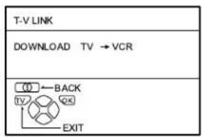
6 Press the OK button to display the T-V LINK menu

7 If you do not have a T-V LINK compatible VCR connected:
Press the TV button to exit the T-V LINK menu.
The T-V LINK menu disappears.
If you have a T-V LINK compatible VCR connected to the EXT-2 terminal:
Follow the operating procedure "Downloading the data to VCR" on page 34 to transmit the Programme number (PR) data.
Now, the initial settings are complete, and you can watch the TV
- When your TV can detect the TV channel name from the TV channel broadcast signal, it automatically registers the TV channel name (ID) to the Programme number (PR) in which the TV channel has been registered.
- If a TV channel you want to view is not set to a Programme number (PR), manually set it using the MANUAL function. For details, see “EDIT/MANUAL” on page 28.
- The TV channel is not registered in Programme number PR 0 (AV). When you want to register a TV channel to PR 0 (AV), manually set it using the MANUAL function. For details, see “EDIT/MANUAL” on page 28.
T-V LINK FUNCTIONS
When a T-V LINK compatible VCR is connected to the EXT-2 Terminal on the TV, it is easier to set up the VCR and to view videos. T-V LINK uses the following features:
To use T-V LINK functions:
A T-V LINK compatible VCR is necessary. The VCR must be connected to the EXT-2 terminal on the TV by a fully wired SCART cable.
A “T-V LINK compatible VCR” means a JVC VCR with the T-V LINK logo or a VCR with one of the following logos. However, these VCRs may support some or all of the features described below. For details, refer to your VCR instruction manual.
"Q-LINK" (a trademark of Panasonic Corporation)
"Data Logic" (a trademark of Metz Corporation)
"Easy Link" (a trademark of Phillips Corporation)
"Megalogic" (a trademark of Grundig Corporation)
"SMARTLINK" (a trademark of Sony Corporation)
■ Pre-set Download
Download the registered data on the TV channels from the TV to the VCR.
The Preset Download function automatically begins when the initial setting is complete or whenever the AUTO PROGRAM or EDIT/MANUAL operations are performed.
- This function can be operated via VCR operation.
When "FEATURE NOT AVAILABLE" is displayed:
If “FEATURE NOT AVAILABLE” is displayed, the download was not performed correctly. Before trying to download again, ensure the following:
• The VCR power is turned on.
- The VCR is T-V LINK compatible.
- The VCR is connected to the EXT-2 terminal.
• The SCART cable is fully wired.
■ Direct Rec
“What You See Is What You Record” You can record to VCR the images that you are currently viewing on TV by a simple operation. For details, read the manual for your VCR. Operate via the VCR. “VCR IS RECORDING” is displayed.
In the following conditions, the VCR will stop recording if the TV is turned off, if the TV channel or input is switched, or if the menu is displayed on the TV:
- When recording images from an external device connected to the TV.
- When recording a TV channel after it has been unscrambled on a decoder.
- When recording a TV channel by using the TV's output because that TV channel cannot be properly received on the VCR's tuner.
- When the VCR is not ready (for example, when there is no tape inserted), “NO RECORDING” is displayed (Excluding AV28CH1EU).
• Operation via the TV is not possible.
- Generally, the VCR cannot record a TV channel that cannot be received properly by the VCR's tuner, even though you can view that TV channel on the TV.
However, some VCRs can record a TV channel by using the TV's output if that channel can be viewed on the TV, even though the TV channel cannot be received properly by the VCR's tuner. For details, refer to your VCR instruction manual.
■ TV Auto Power On/VCR Image View
When the VCR starts playing, the TV automatically turns on and the images from EXT-2 terminal are displayed on the screen. When the VCR menu is operated, the TV automatically turns on and the images from EXT-2 terminal are displayed on the screen.
- This function does not operate if your TV's main power is turned off. Set your TV's main power to on (standby mode).
TV buttons and functions
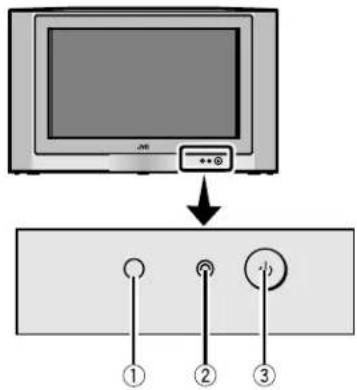


Refer to the pages in parentheses for details.
①Remote control sensor
②Power lamp (3, 8)
③Main power button (3, 8)
④Headphone jack (mini jack) (36)
⑤ P ∨/∧ buttons/ -/+ buttons (8)
⑥△ (Volume) button (8)
⑦EXT-4 terminal (22, 36)
Turn the Main power on
Press the Main power button on the TV.
The Power lamp lights red and your TV is in the standby mode.
- If the Power lamp lights green, the TV is already on.
To turn the Main power off:
Press the Main power button again.
The Power lamp goes off.
Caution
- The main power button on the TV does not fully isolate the TV from the AC supply. If you are not going to use this TV for a long period of time, be sure to disconnect the AC plug from the AC socket.
Turn the TV on from standby mode
Press the P ∨/∧ buttons to turn the TV on from standby mode
Choose a TV channel
Press the P V/Λ buttons to choose a programme number (PR) or an EXT terminal
Adjust the volume
1 Press the △ (Volume) button
The volume level indicator appears.
2 Press the —/A+ buttons while the volume level indicator is displayed
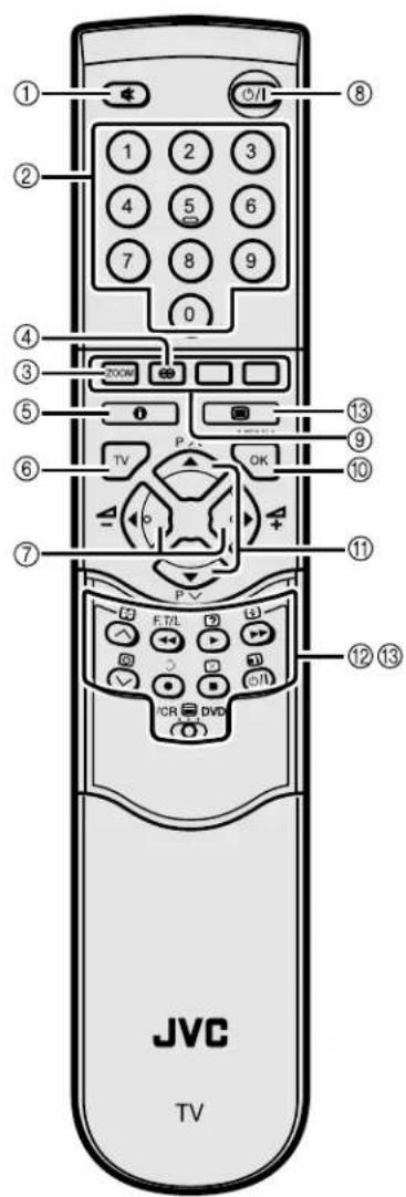
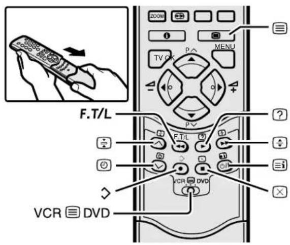
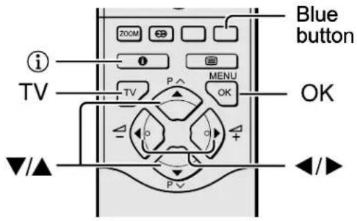
Remote control buttons and functions
natural_image
Illustration of a hand holding a remote control with an arrow indicating rotation (no text or symbols)①Muting button
②Number buttons
③ZOOM button
④HYPER SOUND button
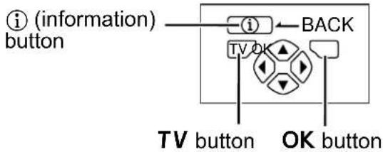
⑤Information button
⑥TV button
⑦◀/▶ buttons
⑧Standby button
⑨Colour buttons
⑩OK button
⑪▼/▲ buttons
⑫VCR/DVD/Teletext control button
⑬ VCR 📋 DVD switch 📋 (Text) button
Turn the TV on or off from standby mode
Press the ⏻/l (standby) button to turn the TV on or off.
When the TV is turned on, the power lamp changes from red to green.
- The power can be turned on by pressing the TV button, ▼/▲ buttons or Number buttons.
Choose a TV channel
■ Use the number buttons: Enter the programme number (PR) of the channel using the number buttons.
Example:
• P R 6 → press 6
- PR12 → press 1 and 2
■ Use the▼/▲ buttons: Press the ▼/▲ buttons to choose the programme number (PR) you want.
■ Use the PR LIST:
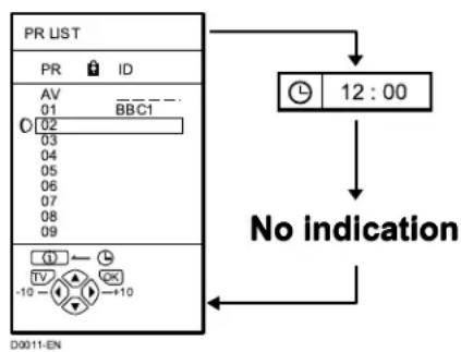
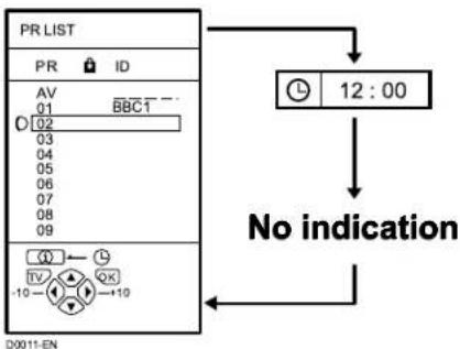
1 Press the ⓘ (Information) button to display the PR LIST
Pressing the ⓘ (information) button changes the display as follows:
flowchart
graph TD
    A["PR LIST"] --> B["AV 01"]
    A --> C["BBC1 02"]
    A --> D["03 04 05 06 07 08 09"]
    A --> E["12:00"]
    E --> F["No indication"]
    F --> G["D0011-EN"]
2 Press the ◀◀▶ and ▼/▲ buttons to choose a Programme number (PR). Then press the OK button
- For Programme numbers (PR) with the CHILD LOCK function set, the Ⓞ (CHILD LOCK) mark is displayed next to the Programme number (PR) in the PR LIST.
- You cannot use the ▼/▲ buttons to choose a Programme number (PR) with the CHILD LOCK function set.
- Even if you try to choose a Programme number (PR) with the CHILD LOCK function set, the Ⓜ (CHILD LOCK) mark will appear, and you cannot watch the TV channel. To watch the TV channel, see “CHILD LOCK” on page 25.
- If the picture is tilted, correct it. See “PICTURE TILT (Excluding AV28CH1EU)” on page 21.
Adjust the volume
Press the ◀/▶ buttons to adjust the volume.
The Volume indicator appears and the volume changes as you press the -/+ buttons.
■ Muting the sound Press the ⚙ (muting) button to turn off the sound.
Pressing the ⚙ (muting) button again restores the previous volume level.
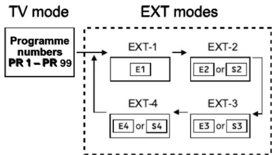
Watch images from external devices
■ Use the O(AV) button: Press the O (AV) button to choose an EXT terminal.
flowchart
graph TD
    A["Programme numbers PR 1–PR 99"] --> B["EXT-1"]
    B --> C["EXT-2"]
    B --> D["EXT-3"]
    D --> E["EXT-4"]
    E --> F["E4 or S4"]
    F --> B
    B --> G["E1"]
    G --> B
    D --> H["E3 or S3"]
    H --> D
■ Use the ▼/▲ buttons: Press the ▼/▲ buttons to choose an EXT terminal.
■ Use the PR LIST:
1 Press the Ⓐ (Information) button to display the PR LIST
2 Press the ◀◀▶ and ▼/▲ buttons to choose an EXT terminal. Then press the OK button
- The EXT terminals are registered after the Programme number PR 99.
- You can choose a video input signal from the S-VIDEO signal (Y/C signal) and regular video signal (composite signal). For details, see “S-IN (S-VIDEO input)” on page 22.
- If you do not have a clear picture or no colour appears, change the colour system manually. See “COLOUR SYSTEM” on page 20.
- If you choose an EXT terminal with no input signal, the EXT terminal number becomes fixed on the screen.
- This TV set has a function which can automatically change over the input according to a special signal output from an external device. (The EXT-4 terminal does not support it.)
To return to a TV channel:
Press the TV button, the ▼/▲ buttons or the Number buttons.
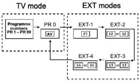
To use the Programme number PR 0 (AV):
When the TV and VCR are connected only by the Aerial cable, choosing the Programme number PR 0 (AV) allows you to view images from the VCR. Set the VCR RF channel to the Programme number PR 0 (AV) manually. For details, see “EDIT/MANUAL” on page 28.
Pressing the O(AV) button changes the choice as follows:
flowchart
graph TD
    A["Programme numbers PR 1–PR 99"] --> B["PR 0"]
    B --> C["AV"]
    C --> D["EXT-1"]
    D --> E["E1"]
    E --> F["EXT-2"]
    F --> G["E2 or S2"]
    G --> H["EXT-3"]
    H --> I["E3 or S3"]
    I --> J["EXT-4"]
    J --> K["E4 or S4"]
    K --> L["EXT-4"]
    L --> M["EXT-4"]
    M --> N["EXT-4"]
    style A fill:#f9f,stroke:#333
    style N fill:#f9f,stroke:#333
• The VCR RF channel is sent as the RF signal from the VCR.
- Also refer to your VCR instruction manual.
ZOOM function
You can change the screen size according to the picture aspect ratio. Choose the optimum one from the following ZOOM modes.
AUTO:
For any picture format except Normal Picture (4:3 Aspect Ratio), the picture will be automatically displayed in the optimum screen size.
For Normal Picture (4:3 Aspect Ratio), the picture displayed in accordance with the ZOOM mode set on the 4:3 AUTO ASPECT menu. For details, see "4:3 AUTO ASPECT" on page 20.
- AUTO may not function properly with poor signal quality. In this case, choose an optimum ZOOM mode manually.
- This TV supports WSS (wide-screen signals). When broadcasts with WSS are received with the ZOOM mode set at AUTO, the most suitable ZOOM mode is automatically chosen according to the WSS received.
REGULAR:
Use to view a normal picture (4:3 aspect ratio) as its original size is.

PANORAMIC:
This mode stretches the left and right sides of a normal picture (4:3 Aspect Ratio) to fill the screen, without making the picture appear unnatural.

• The top and bottom of the picture are slightly cut off.
14:9 ZOOM:
This mode zooms up the Wide Picture (14:9 Aspect Ratio) to the upper and lower limits of the screen.

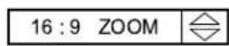
16:9 ZOOM:
This mode zooms up the Wide Picture (16:9 Aspect Ratio) to the full screen.

16:9 ZOOM SUBTITLE:
This mode zooms up the Wide Picture (16:9 Aspect Ratio) with subtitles to the full screen.

FULL:
This mode uniformly stretches the left and right sides of a normal picture (4:3 aspect ratio) to fill the wide TV screen.

Use for pictures with a 16:9 aspect ratio that have been squeezed into a normal picture (4:3 aspect ratio), you can restore their original dimensions.
■ Choose the ZOOM mode
1 Press the ZOOM button to display the ZOOM menu
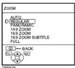
2 Press the ▼▲ buttons to choose a ZOOM mode. Then press the OK button
The picture expands and the chosen ZOOM mode is displayed in about 5 seconds.
• The ZOOM mode may be automatically changed due to the control signal from an external device. When you want to return to the previous ZOOM mode, choose the ZOOM mode again.
■ Adjusting the visible area of the picture
If subtitles or the top (or bottom) of the picture are cut off, adjust the visible area of the picture manually.
1 Press the ZOOM button
The ZOOM menu appears.
2 Press the OK button to display the ZOOM mode indication
Indicator is displayed.
3 While it is displayed, press the ▼▲▲ buttons to adjust the visible area vertically
- You cannot adjust the visible area in REGULAR or FULL mode.
HYPER SOUND function
You can enjoy sounds with a wider ambience.
Press the ⬇ (HYPER SOUND) button to turn the HYPER SOUND function on or off
• The HYPER SOUND function does not work properly with mono sound.
- The HYPER SOUND function can be also turned on or off by using the SOUND SETTING menu. For details, see "HYPER SOUND" on page 22.
Displaying the current time
You can display the Current Time on the screen.
Press the ⓘ (Information) button to display the current time
Pressing the ⓘ (Information) button changes the display as follows:
flowchart
graph TD
    A["PR LIST"] --> B["AV 01 BBCT"]
    A --> C["02 03 04 05 06 07 08 09"]
    A --> D["12:00"]
    D --> E["No indication"]
    E --> F["D0011-EN"]
- This TV uses teletext data to set the current time. If the TV has not received a TV channel that has teletext programmes since it was turned on, the time display is blank. To view the current time, choose a TV channel that has teletext programmes. The time will still be displayed as long as you do not turn off the TV, even if you choose other TV channels.
- When watching videos, an incorrect current time is sometimes displayed.
Return to TV channel instantly
You can return to a TV channel instantly.
Press the TV button
The TV returns to the TV mode and a TV channel appears.
Operating a JVC brand VCR or DVD player
You can operate a JVC brand VCR or DVD player. Pressing the button having the same appearance as the original remote control button of a device makes the function work in the same way as the original remote control.
1 Set the VCR 📄 DVD Switch to the VCR or DVD position
VCR:
When you are operating the VCR, set the switch to the VCR position.
DVD:
When you are operating the DVD player, set the switch to the DVD position.
2 Press the VCR/DVD Control Button to control your VCR or DVD player
- If your device is not made by JVC, these buttons cannot be used.
• Even if your device is made by JVC, some of these buttons or any one of the buttons may not work, depending on the device. - You can use the V//^ buttons to choose a TV channel. The VCR will receive or choose the chapter the DVD player plays back.
- Some DVD player models use the V/Λ buttons for both operating of Fast forward/backward functions and choosing the chapter. In this case, the ◀◀/▶▶ buttons do not work.
Teletext function
Basic operation
You can view three types of teletext broadcasts on the TV: FLOF (Fastext), TOP and WST.
1 Choose a TV channel with a teletext broadcast
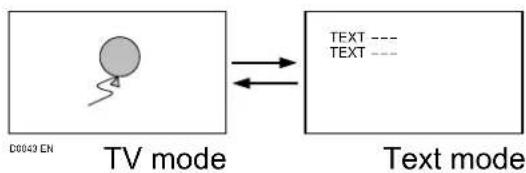
2 Set the VCR 📋 DVD switch to the 📋 (Text) position

3 Press (Text) button to display the teletext
Pressing ☐ (Text) button changes the mode as follows:
flowchart
graph LR
    A["TV mode"] --> B["Text mode"]
    style A fill:#f9f,stroke:#333
    style B fill:#ccf,stroke:#333
4 Choose a teletext page by pressing the ▼/▲ buttons, Number buttons or Colour buttons
To return to the TV mode:
Press the TV button or ☐ (Text) button.
- If you have trouble receiving teletext broadcasts, consult your local dealer or the teletext station.
- The ZOOM function will not operate in the TV and text mode or Text mode.
- No menu operations are possible when viewing a teletext programme.
- Language display depends on the country which was set on the COUNTRY menu. If characters on a Teletext programme do not appear properly, change the COUNTRY Setting to other country's. For detail, "Changing the COUNTRY setting" on page 34.
Using the List Mode
You can store the numbers of your favourite teletext pages in memory and call them up quickly using the colour buttons.
■ To store the page numbers:
1 Press FTTTL button to engage the List mode
The stored page numbers are displayed at the bottom of the screen.
2 Press a Colour button to choose a position. Then press the Number buttons to enter the page number
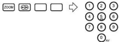
flowchart
graph LR
    A["ZOOM"] --> B["⊕"]
    B --> C[" "]
    C --> D[" "]
    D --> E["1 2 3"]
    E --> F["4 5 6"]
    F --> G["7 8 9"]
    G --> H["0 AV"]
3 Press and hold down ✗ (Store) button
The four page numbers blink white to indicate that they are stored in memory.
■ To call up a stored page:
1 Press the FETTL button to engage the List mode
2 Press a colour button to which a page has been assigned

To exit the List mode:
Press the F.T/L button again.
Hold
You can hold a teletext page on the screen for as long as you want, even while several other teletext pages are being received.
Press the ☐ (Hold) button
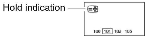
To cancel the Hold function:
Press ☑ (Hold) button again.
Sub-page
Some teletext pages include sub-pages that are automatically displayed.
You can hold any sub-page, or view it at any time.
1 Press the (Sub-page) button to operate the Sub-page function
Sub-page numbers are displayed at the left of the screen.
| Colour* Meaning of sub-page number | |
| Yellow Currently being displayed. | |
| White Can be displayed. | |
| Blue or Red Cannot be displayed and it is not sent. |
*: Background colour of the sub-page number.
2 Press the ▼▲ buttons to choose a sub-page number
To cancel the Sub-page function:
Press the ☑ (Sub-page) button again.
Reveal
Some teletext pages include hidden text (such as answers to a quiz).
You can display the hidden text.
Each time you press the ☐ (Reveal) button, text is hidden or revealed

Size
You can double the height of the teletext display.
Press the ☐ (size) button.
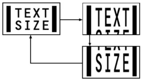
flowchart
graph TD
    A["|TEXT SIZE|"] --> B["|TEXT SIZE|"]
    B --> C["|SIZE|"]
Index
You can return to the index page instantly.
Press ☐ (Index) button
FLOF (Fastext)/TOP/WST:
Returns to page 100 or a previously specified page.
List mode:
Returns to the page number displayed in the lower left area of the screen.
Cancel
You can search for a teletext page while watching TV.
1 Press the Number button to enter a page number, or press a Colour button
The TV searches for a teletext page.
2 Press ☐ (Cancel) button
The TV programme appears. When the TV finds the teletext page, its page number appears in the upper left of the screen.
3 Press 📄 (Cancel) button to return to a teletext page when the page number is on the screen
- The TV mode cannot be resumed even by pressing the ☒ (Cancel) button. A TV programme is temporarily displayed instead of the teletext programme.
Using the TV's menu
This TV has a number of functions you can operate using menus. To fully utilize all your TV's functions, you need to understand the basic menu operating techniques fully.
Basic operation
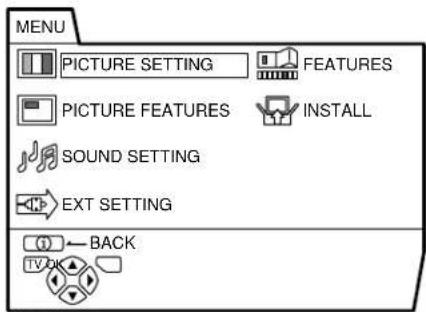
1 Press the OK button to display the MENU (main menu)
D0013-EN
- The display appearing at the bottom of a menu indicates buttons on the remote control you can use when you operate a chosen function.
When a menu is displayed on the screen, the ZOOM mode may be automatically changed to the FULL mode. This is not a malfunction. When the menu disappears, the ZOOM mode will return to the previously set ZOOM mode.
2 Press the ▼▲ buttons to choose a menu title, and press the OK button The menu appears.
To return to the previous menu: Press the ⓘ (information) button.
To exit a menu instantly:
Press the TV button.
3 Press the ▼▲ buttons to choose a function
- For details of the functions in the menus, see the following pages.
4 Press the ◀◀▶ buttons to choose the setting of that function
- If you want to operate a function which appears only with its name, follow the descriptions of that function on the following pages.
- The display appearing at the bottom of a menu shows you a button on the remote control that you can use when you operate a chosen function.
5 Press the OK button to complete the setting
The menu disappears.
- When watching the television with the NTSC system, the menus are displayed at about half of their normal vertical size.
PICTURE SETTING
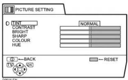
TINT
You can select one of three TINT modes (three kinds of picture settings) to adjust the picture settings automatically.
COOL:
A cool white colour base with a boost in the colour and contrast levels that creates a more vivid picture.
WARM:
A warm orange/red colour base that creates the appropriate colour and contrast levels for watching films.
NORMAL:
A normal white colour base with normal colour and contrast levels.
■ Picture Adjustment
You can change the picture settings of each TINT mode as you like.
CONTRAST:
You can adjust the picture contrast.
◀: lower
▶: higher
BRIGHT:
You can adjust the picture brightness.
◀ : darker
▶ : brighter
SHARP:
You can adjust the picture sharpness.
◀: softer
▶ : sharper
COLOUR:
You can adjust the picture colour.
◀ : lighter
▶ : deeper
HUE:
You can adjust the picture tint.
◀ : reddish
▶: greenish
- You can change the HUE setting (picture hue) only when the colour system is NTSC 3.58 or NTSC 4.43. (See "Specifications" on page 43.)
To return to the default settings in each TINT mode:
Press the blue button.
- This returns the picture settings in the TINT mode you have chosen to the default settings, and stores them in the TINT mode.
PICTURE FEATURES
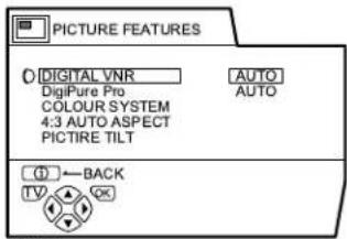
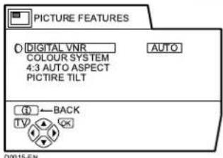
DIGITAL VNR
The DIGITAL VNR function cuts down the amount of noise in the original picture. You can choose from the three DIGITAL VNR function settings of AUTO, MIN and MAX.
AUTO:
The TV will automatically adjust the level of the DIGITAL VNR effect to match the amount of noise in the picture, giving you the best possible picture.
- If you set the DIGITAL VNR effect too high it can make the picture less sharp. It is recommended to use the AUTO setting if you can.
MIN:
The level of the DIGITAL VNR effect is set to the minimum. If you set the DIGITAL VNR function to AUTO but feel that the sharpness of the original picture has not been reproduced fully, change the setting from AUTO to MIN.
- The MIN setting is not suitable for low-quality pictures which contain a lot of noise.
MAX:
The level of the DIGITAL VNR effect is set to the maximum. If you set the DIGITAL VNR function to AUTO but still notice some noise, change the setting from AUTO to MAX.
- The MAX setting is not suitable for high-quality pictures which contain very little noise.
■ DigiPure Pro (only for AV32X25EU/AV28X25EU)
The DigiPure Pro function uses the latest in digital technology to give you a natural-looking picture. The DigiPure Pro function includes the following two functions.
DigiPure function:
This function helps to create a natural-looking picture by eliminating unnecessary edges from high-contrast and crisp images. For images with low-contrast, edges are added to produce a sharper, more detailed picture.
You can choose from the three DigiPure function settings of AUTO, MIN and MAX.
- If you set the DigiPure effect too high on a low-quality picture that contains a lot of noise, this may actually make the noise worse. We recommend you use the AUTO setting if you can.
Picture motion compensation function:
This function displays fast-moving pictures (for example, the players or ball in a football game) more smoothly and naturally on the screen.
- The effect level of the picture motion compensation function cannot be changed. The effect level is the same no matter which of the AUTO, MIN or MAX settings is used.
1 Choose DigiPure Pro
2 Press the ◀◀▶ buttons to choose a setting. Then press the OK button
AUTO:
The TV will automatically adjust the level of the DigiPure effect to match the amount of noise in the picture, giving the best possible picture.
MIN:
The level of DigiPure effect is set to the minimum. When you set the DigiPure Pro function to AUTO and notice some noise, change the setting from AUTO to MIN.
- The MIN setting is not suitable for high-quality pictures which contain very little noise.
MAX:
The level of DigiPure effect is set to the maximum. If you set the DigiPure Pro function to AUTO but feel that the original picture quality has not been reproduced fully, change the setting from AUTO to MAX.
- The MAX setting is not suitable for low-quality pictures which contain a lot of noise.
OFF:
The DigiPure Pro function is turned off.
COLOUR SYSTEM
The colour system is chosen automatically. However, if the picture is not clear or no colour appears, choose the colour system manually.
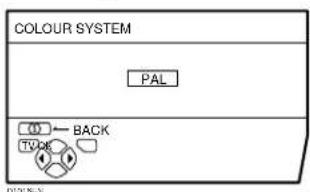
1 Choose COLOUR SYSTEM then press the OK button
2 Press the ◀◀▶ buttons to chose the appropriate colour system. Then press the OK button
PAL:
PAL system
SECAM:
SECAM system
NTSC 3.58:
NTSC 3.58 MHz system
NTSC 4.43:
NTSC 4.43 MHz system
AUTO:
This function detects a colour system from the input signal. Only when you are viewing a picture from Programme number PR 0 (AV), or EXT terminal, you can choose using the AUTO function.
- The AUTO function may not function properly if you have poor signal quality. If the picture is abnormal in the AUTO function, choose another colour system manually.
- When in the Programme numbers PR 0 (AV) to PR 99, you cannot choose NTSC 3.58 or NTSC 4.43.
■ 4:3 AUTO ASPECT
You can choose one of three ZOOM modes, REGULAR, PANORAMIC or 14:9 ZOOM, as the ZOOM mode for the normal picture (4:3 aspect ratio).
1 Choose 4:3 AUTO ASPECT then press the OK button
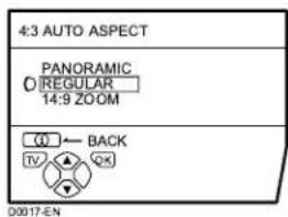
2 Press the ▼▲ buttons to choose a ZOOM mode
■ PICTURE TILT (Excluding AV28CH1EU)
There are cases where the Earth's magnetic force may make the picture tilt. If this happens, you can correct the picture tilt.
1 Press the ▼▲ buttons to choose PICTURE TILT. Then press the OK button
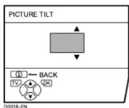
2 Press the ▼▲ buttons until the picture becomes level. Then press the OK button
SOUND SETTING
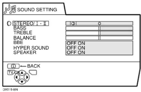
■ STEREO / I • II
When you are viewing a bilingual broadcast programme, you can choose the sound from Bilingual I (Sub I) or Bilingual II (Sub II). When the stereo broadcasting is received poorly, you can change from stereo to mono sound so that you can hear the broadcast more clearly and easily.
∞: Stereo sound
O::mono sound
- The sound mode you can choose differs depending on the TV programme.
- This function does not work in the EXT modes. And this function does not appear in the SOUND SETTING menu.
■ Sound Adjustment
You can adjust the sound to your liking.
BASS:
You can adjust the low tone of the sound.
◀ : weaker
▶ : strong
TREBLE:
You can adjust the high tone of the sound.
◀ : weaker
▶ : strong
BALANCE:
You can adjust the volume balance between the left and right speaker.
◀: turn the left speaker's volume level up.
▶: turn the right speaker's volume level up.
BBE
You can use the BBE function to enjoy easy-to-listen sound that is faithful to the original sound recorded.
ON:
This function is turned on.
OFF:
This function is turned off.
Licensed by BBE Sound, Inc. BBE is a registered trademark of BBE Sound, Inc.
■ HYPER SOUND
You can enjoy sounds with a wider ambience.
ON:
This function is turned on.
OFF:
This function is turned off. The menu disappears.
• The HYPER SOUND function does not work properly with mono sound.
- You can turn on or off the HYPER SOUND function with a single press. For details, see “HYPER SOUND function” on page 12.
■ SPEAKER
(Excluding AV28CH1EU)
You can turn off the sound from the TV speakers; but you should only do this if an audio system is connected to the TV as a substitute for the TV speakers.
ON:
The TV speakers issue sound.
OFF:
The TV speakers does not issue sound.
- The ◀/▶ buttons of the TV remote control and the △ (volume) buttons at the front panel of your TV set can be used to control the volume of each speaker simultaneously.
- Setting the volume of the amplifier too high may damage the front speakers.
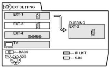
EXT SETTING
flowchart
graph TD
    A["EXT SETTING"] --> B["EXT-1"]
    A --> C["EXT-3"]
    A --> D["EXT-4"]
    A --> E["TV"]
    F["DUBBING EXT-2"] --> G["ID LIST"]
    F --> H["S-IN"]
    I["Back"] --> J["TV"]
    K["OK"] --> L["+"]
■ S-IN (S-VIDEO input)
When connecting a device (such as S-VHS VCR) which enables an S-VIDEO signal (Y/C signal) to be output, you can enjoy high-quality picture of the S-VIDEO signal (Y/C signal).
Preparation:
- At first, read the Device Instruction Manual and “Additional preparation” on page 36 to connect the device to the TV properly. Second, follow the Device Instruction Manual to set the device so that an S-VIDEO signal (Y/C signal) can be output to the TV.
- Do not set S-IN (S-VIDEO input) to the EXT terminal connected to a device which cannot output an S-VIDEO (Y/C signal). If it is set wrongly, a picture cannot appear.
1 Choose an EXT terminal
2 Press the yellow button and set the S-IN (S-VIDEO input).
Then press the OK button
An S-IN (S-VIDEO input) mark is displayed. You can view an S-VIDEO signal (Y/C signal) instead of the regular video signal (composite signal).
To cancel the S-IN (S-VIDEO input) setting:
Press the yellow button and turn off S-IN (S-VIDEO input) mark. The regular video signal (composite signal) pictures are resumed.
- The EXT-1 terminal does not support S-VIDEO signal (Y/C signal) and you cannot set S-IN (S-VIDEO input) in the EXT-1 terminal.
- Setting S-IN (S-VIDEO input) changes the head character from "E" to "S". For example, "E2" is changed to "S2".
- Even a device which enables the S-VIDEO signal (Y/C signal) to be output may output a regular video signal (composite signal) depending on the device setting. If a picture cannot appear because S-IN (S-VIDEO input) setting has been made, read the device Instruction Manual carefully again to check for the device settings.
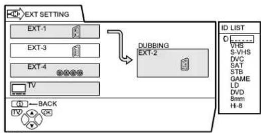
ID LIST
You can have a name corresponding to the devices connected for each EXT terminal. Giving a name to an EXT terminal makes the EXT terminal number appear on the screen, together with the name.
1 Choose an EXT terminal
2 Press the blue button to display the name list (ID LIST)
flowchart
graph TD
    A["EXT SETTING"] --> B["EXT-1"]
    A --> C["EXT-3"]
    A --> D["EXT-4"]
    A --> E["TV"]
    F["DUBBING"] --> G["EXT-2"]
    H["ID LIST"] --> I["0 VHS S-VHS DVC SAT STB GAME LD DVD 8nm HI-8"]
    J["BACK"] --> K["TV"]
D0021-EN
3 Press the ▼▲ buttons to choose a name. Then press the OK button The ID LIST disappears and the name is assigned to the EXT terminal.
- You cannot assign an EXT terminal name not found in the name list (ID LIST).
To erase a name assigned to the EXT terminal:
Choose a blank space.
4 Press the OK button to complete the setting
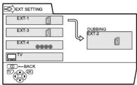
■ DUBBING
You can choose a signal source to be output from an EXT-2 terminal.
You can choose any one of the output signal of the device connected to the EXT terminal and the picture and sound from a TV channel you are currently viewing to output it to the EXT-2 terminal.
1 Press the ◀◀▶ buttons to choose the arrow from the menu
flowchart
graph TD
    A["EXT SETTING"] --> B["EXT-1"]
    A --> C["EXT-3"]
    A --> D["EXT-4"]
    A --> E["TV"]
    F["DUBBING"] --> G["EXT-2"]
    H["BACK"] --> I["TV"]
D0022-EN
2 Press the ▼▲▲ buttons to choose an EXT terminal or TV. Then press the OK button
The arrow in the menu represents a signal flow. The left side of the arrow denotes a signal source output from the EXT-2 terminal.
EXT-1/EXT-3/EXT-4:
The output signal of the device connected to an EXT terminal passes through the TV and is output from the EXT-2 terminal.
TV:
The picture and sound of the TV channel you are currently viewing are output from the EXT-2 terminal.
- During dubbing, you cannot turn off the TV. Turning off the TV also turns off the output from the EXT-2 terminal.
- When you choose an EXT terminal as an output, you can view a TV programme or a picture from the other EXT terminal while dubbing the picture from a device connected to the EXT terminal onto a VCR connected to the EXT-2 terminal.
- The RGB signals from the TV games cannot be output. Teletext programmes cannot be output.
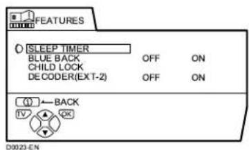
FEATURES
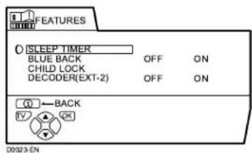
■ SLEEP TIMER
You can set the TV to automatically turn off after a specified period of time.
1 Choose SLEEP TIMER, then press the OK button
A Sub-menu of the SLEEP TIMER function appears.
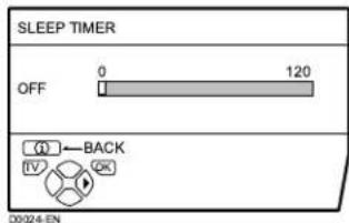
2 Press the ◀◀▶ buttons to set the period of time.
Then press the OK button
You can set the period of time a maximum of 120 minutes (2 hours) in 10 minute increments.
- One minute before the SLEEP TIMER function turns off the TV, “GOOD NIGHT!” appears.
- The SLEEP TIMER function cannot be used to turn off the TV's main power.
- When the SLEEP TIMER function is on, you can display the Sub-menu of the SLEEP TIMER function again to confirm and/or change the remaining period of time of the SLEEP TIMER function. Press the OK button to exit the menu after confirming and / or changing the remaining time.
To cancel the SLEEP TIMER function:
Press the ◀ button to set a period of time to "OFF".
BLUE BACK
You can set the TV to automatically change to a blue screen and mute the sound if the signal is weak or absent, or when there is no input from an external device.
ON:
This function is turned on.
OFF:
This function is turned off.
CHILD LOCK
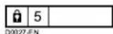
When there is a TV channel you wish your children not to watch, you can use the CHILD LOCK function to lock out the TV channel. Even when a child chooses a Programme number (PR) in which a locked TV channel has been registered, the screen will change to blue and displays Ⓞ (CHILD LOCK) so the TV channel cannot be viewed. Unless you enter a pre-set ID number by a special operation, the lock cannot be released and the child cannot view the TV channel programmes.
To set the CHILD LOCK function
1 Choose CHILD LOCK, then press the 0(AV) button
"SET ID NO." (ID number setting screen) appears.
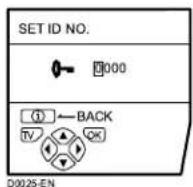
2 Set the ID number to your liking
1 Press the ▼/▲ buttons to choose a number.
2 Press the ◀/▶ buttons to move the cursor.
3 Press the OK button
The Sub-menu of CHILD LOCK appears.
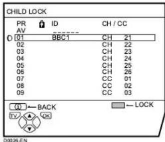
4 Press the ▼▲ buttons to choose a TV channel
Every time you press the ▼/▲ buttons, the Programme number (PR) changes, and the picture of the TV channel registered in the Programme number (PR) is displayed on the screen.
5 Press the blue button and set the CHILD LOCK function.
Then press the OK button
(CHILD LOCK) appears and the TV channel is locked.
To reset the CHILD LOCK function:
Press the blue button again.
(CHILD LOCK) disappears.
To disable easy resetting of the CHILD LOCK function, the menu disappears by choosing the CHILD LOCK function and pressing the OK button as in the ordinary menu operation.
To view a locked TV channel
1 Choose a Programme number (PR) in which a TV channel locked with the Number buttons or PR LIST
The screen changes to blue and the ⏻ (CHILD LOCK) appears. You cannot view the TV channel.
2 Press the ① (Information) button to display "ID NO." (ID NO. input screen).
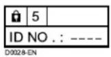
3 Press the Number buttons to enter the ID number
The lock is temporarily released so you can view the TV channel.
If you have forgotten the ID number:
Perform step 1 of “To set the CHILD LOCK function”. After confirming the ID number, press the TV button to exit the menu.
- Even if you reset the lock temporarily, it does not mean that the CHILD LOCK function set for the TV channel is cancelled. The next time anyone attempts to view the TV channel, it will be locked again.
- When you would like to cancel the CHILD LOCK function, you must perform the operation “To set the CHILD LOCK function” again.
- To disable easy choosing of a Programme number (PR) in which a locked TV channel has been registered, the Programme number (PR) has been set that it cannot be chosen by the ▼/▲ buttons or the operation buttons at the TV.
- To disable easy resetting of the lock, "ID NO." (ID NO. input screen) is set so that it cannot appear unless you press the ① (Information) button.
■ DECODER (EXT-2)
Only when connecting a Decoder with a T-V LINK compatible VCR connected to the EXT-2 terminal, you can use this function. To operate this function, see “Using the DECODER (EXT-2) function” on page 35.
Caution
- If you have not connected a Decoder with a T-V LINK compatible VCR connected to the EXT-2 terminal, setting this function to "ON" by mistake causes the picture/sound of a TV channel you are currently viewing not to be issued.
INSTALL
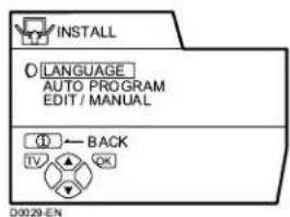
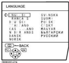
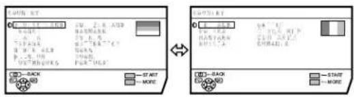
LANGUAGE
You can choose the language you want to use for the on-screen display from the language list in a menu.
1 Choose LANGUAGE, then press the OK button
A sub-menu of the LANGUAGE function appears.
![LANGUAGE O NG S - RANCAIS D-U SCI A ANO CAS I ANO N-D-R ANDS DANSK NORSK SV NSKA SUOM PO_SK: C SKY MAGTAR БЫЛГАРСКИ РУССКИЙ [1] ← BACK TV QX D0002(E)-EN](/content/2026/02/377671/images/47b9a90c4dbd0a466c334ae21ca33fb42b300b52cb4bccf7741c415a9e814347.jpg)
2 Press the ◀◀▶ and ▼/▲ buttons to choose a language. Then press the OK button
■ AUTO PROGRAM
You can automatically register the TV channels which can be received well at your residence in the TV's Programme numbers (PR) by performing the following.
1 Choose AUTO PROGRAM. Then press the OK button
The COUNTRY menu appears as a sub-menu of the AUTO PROGRAM function. There are two COUNTRY menus. Pressing the yellow button changes the COUNTRY menu as follows:
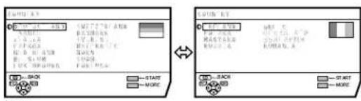
2 Press the ◀◀▶ and ▼/▲ buttons to choose the country where you are now located
3 Press the blue button to start the AUTO PROGRAM function
The AUTO PROGRAM menu appears and received TV channels are automatically registered in the Programme numbers (PR).
• To cancel the AUTO PROGRAM function, press the TV button.
After the TV channels have been registered in the Programme numbers (PR), the EDIT menu appears.
- You can proceed to edit the Programme numbers (PR) using the EDIT/MANUAL function. For details, see “EDIT/MANUAL” on page 28.
- If you do not need to use the EDIT/MANUAL function, go to the next step.
If "ACI START/ACI SKIP" appears in the AUTO PROGRAM menu:
You can use the ACI (Automatic Channel Installation) function to decode the ACI data and complete the registration of all the TV channels in a short period of time. For details of the ACI function and how to use it, refer to "Using the ACI function" on page 33. If you don't want to use the ACI function, press the ▼/▲ buttons to choose ACI SKIP and then press OK.
4 Press the OK button to display the T-V LINK menu

5 If you do not have a T-V LINK compatible VCR connected:
Press the TV button to exit the T-V LINK menu.
If you have a T-V LINK compatible VCR connected to the EXT-2 terminal:
Follow the operating procedure "Downloading the data to VCR" on page 34 to transmit the Programme number (PR) data.
- When your TV can detect the TV channel name from the TV channel broadcast signal, it automatically registers the TV channel name (ID) to the Programme number (PR) in which the TV channel has been registered.
- If a TV channel you want to view is not set to a Programme number (PR), manually set it using the MANUAL function. For details, see “EDIT/MANUAL” on page 28.
- The TV channel is not registered in Programme number PR 0 (AV). When you want to register a TV channel to PR 0 (AV) manually set it using the MANUAL function. For details, see "EDIT/MANUAL" on page 28.
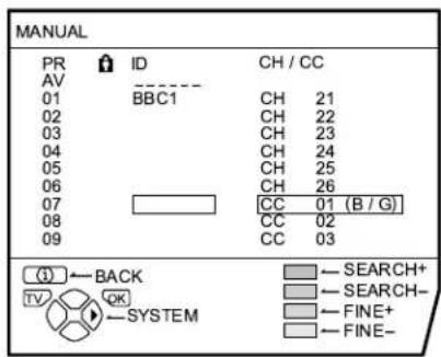
EDIT/MANUAL
The EDIT/MANUAL functions are divided into two types: editing of the current Programme numbers (PR) (EDIT functions) and manual registration of a TV channel you want to view to the Programme number (PR) (MANUAL function). The details about these functions are as follows:
Caution
- Using the MOVE, DELETE or INSERT function rewrites the current Programme numbers (PR) list. Resultingly, the Programme number (PR) of some of the TV channels will change.
• Using the MANUAL function for a TV channel for which the CHILD LOCK function has been set cancels the CHILD LOCK function for the TV channel. - Using the MANUAL function for a TV channel for which the DECODER (EXT-2) function has been set to ON returns the setting of the DECODER (EXT-2) function for the TV channel to OFF.
- When a TV channel has already been registered in PR 99, using the INSERT function deletes the TV channel.
1 Choose EDIT/MANUAL, then press the OK button
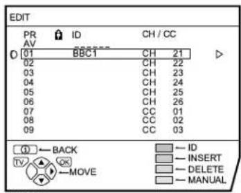
- For Programme number PR 0, "AV" appears in the Programme numbers (PR) list.
- An EXT terminal number does not appear in the Programme numbers (PR) list.
- The CH/CC number is a number unique to the TV and corresponding to the Channel number of a TV channel. For the relationship of a Channel number and a CH/CC number, see “CH/CC numbers” on page 38.
2 Follow the operation description of a function you want to use and operate the function
MOVE:
This function changes a Programme number (PR) of a TV channel.
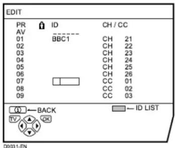
ID:
This function registers a Channel name (ID) to a TV channel.
INSERT:
This function adds a new TV channel in the current Programme numbers (PR) list by using the CH/CC number.
- You cannot use the INSERT function if you do not know a Channel number of a TV channel. Use the MANUAL function to register a TV channel in the Programme number (PR).
DELETE:
This function deletes an unnecessary TV channel.
MANUAL:
This function manually registers a new TV channel in a Programme number (PR).
3 Press the OK button to complete the settings
The T-V LINK menu appears.
4 If you do not have a T-V LINK compatible VCR connected:
Press the TV button to exit the T-V LINK menu.
The T-V LINK menu disappears and all the settings are completed.
If you have a T-V LINK compatible VCR connected to the EXT-2 terminal:
Follow the operating procedure "Downloading the data to VCR" on page 34 to transmit the Programme number (PR) data to the VCR.
MOVE
1 Press the ▼▲ buttons to choose a TV channel
Every time you press the ▼/▲ buttons, the Programme number (PR) is changed over, and the picture of the TV channel registered in the Programme number (PR) appears on the screen.
2 Press the ▶ button to start the MOVE function
3 Press the ▼▲ buttons to choose a new Programme number (PR)
To cancel the MOVE function:
Press the ⓘ (Information) button.
4 Press the ◀ button to change the Programme number (PR) of a TV channel to a new Programme number (PR)
ID
1 Press the ▼▲ buttons to choose a TV channel
Every time you press the ▼/▲ buttons, the Programme number (PR) is changed over, and the picture of the TV channel registered in the Programme number (PR) appears on the screen.
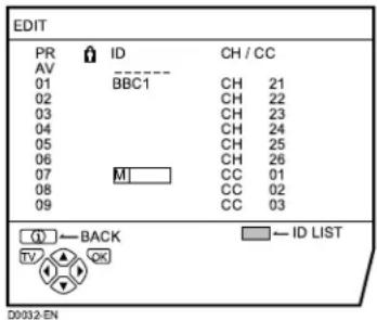
2 Press the red button to start the ID function
3 Press the ▼▲▲ buttons to choose the first character of a Channel name (ID) you want to attach to the TV channel
4 Press the blue button to display the ID LIST (channel name list)
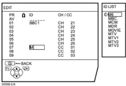
5 Press the ▼▲ buttons to choose the Channel name (ID)
To cancel the ID function:
Press the ⓘ (Information) button.
6 Press the OK button to register a Channel name (ID) to a TV channel
- You can register your unique Channel name (ID) to the TV channel. When step 3 is completed, do not go to step 4, but press the ◀/▶ buttons to move the cursor and the ▼/▲ buttons to choose a character for completing the Channel name (ID). Then press the OK button to register the Channel name (ID) to the TV channel.
INSERT
Preparation:
- A CH/CC number unique to this TV and corresponding to the Channel number of a TV channel is required. Find the corresponding CH/CC number from a table “CH/CC numbers” on page 38 based on the Channel number of the TV channel.
- When the COUNTRY setting is not FRANCE, use a two-digit CH/CC number. When the COUNTRY setting is FRANCE, use a three-digit CH/CC number.
- Only when you add a TV channel (SECAM-L system) from a French station, be sure to set COUNTRY to FRANCE. If the COUNTRY setting is not FRANCE, follow the description “Changing the COUNTRY setting” on page 34 to change the COUNTRY setting to FRANCE, then start the INSERT function.
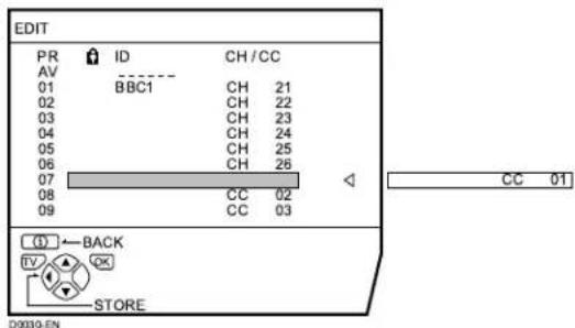
1 Press the ▼▲ buttons to choose a Programme number (PR) for which you will register a new TV channel
2 Press the green button and start the INSERT function.
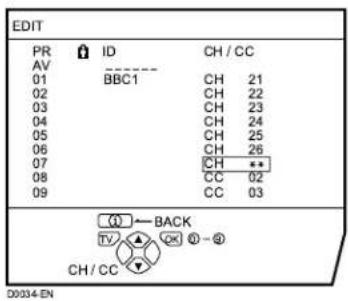
3 Press the ▼▲ buttons to choose "CC" or "CH" according to the CH/ CC number of the TV channel
When the COUNTRY setting is FRANCE:
Choose "CH1", "CH2", "CC1" or "CC2".
To cancel the INSERT function:
Press the ⓘ (Information) button.
4 Press the Number buttons to enter the remaining CH/CC number
The TV shifts to registration mode. When the registration is completed, the picture of the TV channel appears on the screen.
• The CH/CC number is a number indicating the broadcast frequency to the TV. If the TV cannot detect the TV channel corresponding to the broadcast frequency indicated by the CH/CC number, a picture in the no-signal state appears.
DELETE
1 Press the ▼▲ buttons to choose a TV channel
Every time you press the ▼/▲ buttons, the Programme number (PR) is changed over, and the picture of the TV channel registered in the Programme number (PR) appears on the screen.
2 Press the yellow button to delete the TV channel
The TV channel is deleted from the Programme numbers (PR) list.
MANUAL
Preparation:
- As long as you register the TV channel (SECAM-L system) from a French station, be sure to set the COUNTRY setting to FRANCE. If the COUNTRY setting is not FRANCE, follow the description “Changing the COUNTRY setting” on page 34 to change the COUNTRY setting to FRANCE, then start the MANUAL function.
1 Press the ▼▲ buttons to choose a Programme number (PR) to which you want to register a new TV channel
2 Press the blue button to activate the MANUAL function
At the right side following the CH/CC number, the SYSTEM (broadcasting system) of the TV channel appears.
D0035-EN
To cancel the MANUAL function: Press the ⓘ (Information) button.
3 Press the ▶ button to choose the SYSTEM (broadcasting system) for a TV channel you want to register
TV channel (SECAM-L system) from a French station:
Set the SYSTEM to "L". If it is set to one other than "L", you cannot receive the TV channel of the SECAM-L system.
Other TV channels:
If you do not know the correct broadcasting system, set the SYSTEM to "B/G". If "B/G" is not correct, it results in the fact that you will not hear the sound normally when the TV detects a TV channel. In this case, retry to set the SYSTEM again correctly so that no problem arises.
4 Press the green or red button to search for a TV channel
Scanning stops when the TV finds a TV channel. Then the TV channel is displayed.
5 Press the green or red button repeatedly until the TV channel you want appears
If the TV channel reception is poor:
Press the blue or yellow button to fine-tune the TV channel.
If you cannot hear the normal sound even when the picture of the TV channel appears normally:
The SYSTEM setting is wrong. Press the ▶ button and choose a SYSTEM that has normal sound.
6 Press the OK button and register the TV channel to a Programme number (PR)
The normal EDIT menu is resumed.
Additional menu operations
Using the ACI function
This TV has an ACI function which decodes the ACI (automatic Channel Installation) data.
Using the ACI function allows all TV channels transmitted from the cable TV station to be properly registered quickly according to the data from the cable TV station.
Caution
- If your cable TV station broadcasts ACI data and if "ACI START/ACI SKIP" appears in the AUTO PROGRAM menu, the ACI function is enabled. In all other cases, it is disabled.
1 Press the ▼▲ buttons to choose ACI START. Then press the OK button to start the ACI function
When you don't want to use the ACI function:
Press the ▼/▲ buttons to choose ACI SKIP and then press the OK button.
If the AUTO PROGRAM menu changes to another menu:
Depending on your cable TV station, there may be a broadcast selection menu set up by the cable TV station.
Follow the menu indications and use the
◀/▶ and ▼/▲ buttons to operate the menu. After you have made the setting, press the OK button.
If "ACI ERROR" is displayed in the AUTO PROGRAM menu:
“ACI ERROR” denotes that the ACI function is not working properly. Press the OK button to start the ACI function again.
If “ACI ERROR” still appears even after you have tried to start the ACI function several times, press the ▶ button to start the AUTO PROGRAM function. It does not cause any problem because all the TV channels are registered to the Programme numbers (PR) by the AUTO PROGRAM function.
2 When the settings are completed, the EDIT menu is displayed. Return to the instructions that you were reading before, and continue the operation
When the "Initial settings" has been made:
Return to step 6 of "Initial settings" on page 5.
When the "AUTO PROGRAM" has been made:
Return to step 4 of "AUTO PROGRAM" on page 28.
- If you have any questions about the items in the Broadcast Selection menu or how to operate the menu, please contact your cable TV station.
- When the cable TV broadcast reception is poor, the ACI function will not work properly.
- If there is an error in the ACI data itself, the TV channel cannot be registered properly. If this happens, turn the ACI function off (ACI SKIP) and use the AUTO PROGRAM function. Alternatively, use the EDIT/MANUAL function to correct the Programme number (PR) setting.
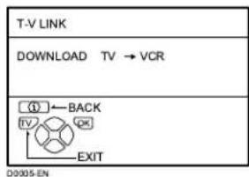
Downloading the data to VCR
You can transmit to the latest Programme numbers (PR) data to the VCR with the T-V LINK function.
Caution
- Only when the T-V LINK compatible VCR is connected to the EXT-2 terminal, this operation is enabled.
- Only when the T-V LINK menu is being displayed, this operation is enabled.

D0005-EN
1 Turn on the VCR
2 Press the OK button
The data transmission begins.
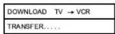
D0037-EN
The T-V LINK menu disappears once the data transmission ends.
When the T-V LINK menu is changed over to another menu:
The menu operation at the TV side is completed and it is shifted to the menu operation at the VCR side. Refer to the VCR Instruction Manual and operate the VCR.
If "FEATURE NOT AVAILABLE" appears at the T-V LINK menu, ensure the following three items are correct; then press the OK button to retry data transmission.
- Has the T-V LINK compatible VCR been connected to the EXT-2 terminal?
- Has the VCR power been turned on?
- Does the SCART cable that is connected to the EXT-2 terminal to T-V LINK compatible VCR have all proper connections?
Changing the COUNTRY setting
After the AUTO PROGRAM function is completed, you can change the country you have already set by using the AUTO PROGRAM function.
When registering the TV channels for French broadcast stations (SECAM-L system), perform this operation to change the country.
1 Display the INSTALL menu
When the EDIT menu is currently being displayed:
Press the ⓘ (Information) to return to the INSTALL menu.
2 Press the ▼▲ buttons to choose AUTO PROGRAM. Then press the OK button
A COUNTRY menu appears as a sub-menu of the AUTO PROGRAM function. There are two COUNTRY menus. Pressing the yellow button changes the COUNTRY as follows:
3 Press the ◀◀▶ and the ▼/▲ buttons to choose a country
4 Press the OK button to complete the setting
The menu disappears.
To return to the INSTALL menu from the COUNTRY menu:
Press the ⓘ (Information) button instead of the OK button.
Using the DECODER (EXT-2) function
When connecting a Decoder with a T-V LINK compatible VCR connected to the EXT-2 terminal, use the DECODER (EXT-2) function to unscramble the scrambled TV channels.
1 Turn on the Decoder power
2 Display the TV channel capable of being unscrambled with the Decoder on the TV
Even if the Decoder is functioning, a scrambled picture appears at this time.
3 Press the OK button to display the MENU
The MENU (main menu) appears.
4 Press the ▼▲ buttons to choose FEATURES. Then press the OK button
The FEATURES menu appears.
5 Press the ▼▲ buttons to choose DECODER (EXT-2). Then press the ◀/▶ buttons to choose ON
An unscrambled picture appears.
To cancel the DECODER (EXT-2) function:
Press the ◀/▶ buttons to choose OFF.
6 Press the OK button to complete the setting
The T-V LINK menu appears.
7 Follow the operating procedure "Downloading the data to VCR" on page 34 to transmit the Programme number (PR) data to the VCR
8 If you have another TV channel capable of being unscrambled with a Decoder, repeat steps 2 through 7
If for some reason the DECODER (EXT-2) function has been set to "ON" but the TV channel cannot be unscrambled, check the following:
- Has the Decoder been connected to the VCR properly according to the VCR and Decoder Instruction Manuals?
- Has the Decoder power been turned on?
- Can the TV channel be unscrambled with a Decoder?
- Is it necessary to change the VCR settings in order to connect the Decoder? Confirm that the VCR is set properly by rechecking the VCR Instruction Manual.
Additional preparation
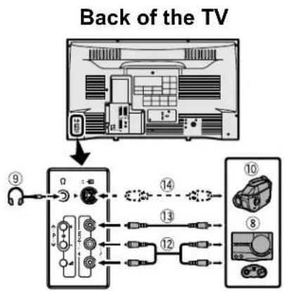
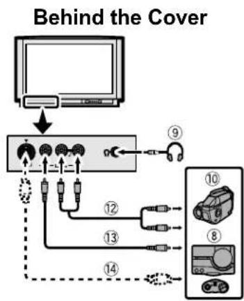
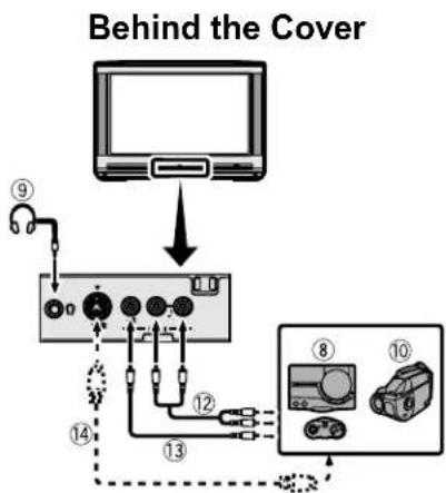
Connecting the external devices
Connect the devices to the TV, paying attention to the following connection diagram.
Before connecting anything:
- Read the manuals provided with the devices. Depending on the devices, the connection method may differ from the figure. In addition, the device settings may be changed depending on the connection method to secure proper operation.
- Turn off all the devices including the TV.
- The “Specifications” on page 43 contains the details of the EXT terminals. If you are connecting a device not listed in the following connection diagram, see the table to choose the best EXT terminal.
- Note that connecting cables are not supplied.
①VCR (composite signal) ②VCR (composite signal/S-VIDEO signal) ③T-V LINK compatible VCR (composite signal/S-VIDEO signal)
④Decoder ⑤DVD player (composite signal/S-VIDEO signal) ⑥DVD player (composite signal/RGB signal)
⑦TV game (composite signal/RGB signal)
⑧TV game (composite signal/S-VIDEO signal)
⑨Headphones ⑩Camcorder (composite signal/S-VIDEO signal)
⑪SCART cable
⑫Audio cable
⑬Video cable
⑭S-VIDEO cable
flowchart
graph TD
    A["Antenna"] --> B["Signal ⑨"]
    B --> C["Antenna ⑩"]
    C --> D["Output ⑪"]
    C --> E["Antenna ⑬"]
    E --> F["Output ⑩"]
    C --> G["Antenna ⑭"]
    G --> H["Output ⑧"]
flowchart
graph TD
    A["Monitor"] --> B["Device 1"]
    B --> C["Device 2"]
    C --> D["Device 3"]
    D --> E["Device 4"]
    E --> F["Device 5"]
    F --> G["Device 6"]
    G --> H["Device 7"]
    H --> I["Device 8"]
    I --> J["Device 9"]
    J --> K["Device 10"]
    style A fill:#f9f,stroke:#333
    style K fill:#bbf,stroke:#333
flowchart
graph TD
    A["Behind the Cover"] --> B["Monitor"]
    B --> C["Device ⑨"]
    B --> D["Device ⑪"]
    B --> E["Device ⑬"]
    B --> F["Device ⑭"]
    B --> G["Device ⑮"]
    B --> H["Device ⑰"]
    B --> I["Device ⑱"]
Back of the TV
flowchart
graph TD
    A["Port 4"] --> B["Port 3"]
    C["Port 2"] --> D["Port 5"]
    E["Port 6"] --> F["Port 7"]
    G["Port 8"] --> H["Port 1"]
    I["Port 1"] --> J["Port 2"]
    K["Port 7"] --> L["Port 1"]
    M["Port 1"] --> N["Port 2"]
    O["Port 1"] --> P["Port 1"]
    Q["Port 1"] --> R["Port 1"]
    S["Port 1"] --> T["Port 1"]
    U["Port 1"] --> V["Port 1"]
    W["Port 1"] --> X["Port 1"]
    Y["Port 1"] --> Z["Port 1"]
    AA["Port 1"] --> AB["Port 1"]
    AC["Port 1"] --> AD["Port 1"]
    AE["Port 1"] --> AF["Port 1"]
    AG["Port 1"] --> AH["Port 1"]
    AI["Port 1"] --> AJ["Port 1"]
    AK["Port 1"] --> AL["Port 1"]
    AM["Port 1"] --> AN["Port 1"]
    AO["Port 1"] --> AP["Port 1"]
    AQ["Port 1"] --> AR["Port 1"]
    AS["Port 1"] --> AT["Port 1"]
    AU["Port 1"] --> AV["Port 1"]
    AW["Port 1"] --> AX["Port 1"]
    AY["Port 2"] --> Z
    AZ["Port 2"] --> AA
    BA["Port 2"] --> AB
    BB["Port 2"] --> AC
    BC["Port 2"] --> AD
    BD["Port 2"] --> AE
    BE["Port 2"] --> AF
    BF["Port 2"] --> AG
    BG["Port 2"] --> AH
    BH["Port 2"] --> AI
    AJ["Port 2"] --> AK
    AL["Port 2"] --> AM
    AM --> AN
    AN --> AO
    AO --> AP
    AP --> AQ
    AQ --> AR
    AR --> AS
■ Devices which can output the S-VIDEO signal (Y/C signal) such as a S-VHS VCR
Connect the device to an EXT terminal other than the EXT-1 terminal.
You can choose a video input signal from the S-VIDEO signal (Y/C signal) and regular video signal (composite signal). For details of how to operate the device, see “S-IN (S-VIDEO input)” on page 22.
■ T-V LINK compatible VCR
Be sure to connect the T-V LINK compatible VCR to the EXT-2 terminal. If not, the T-V LINK function will not work properly.
- When connecting a T-V LINK compatible VCR to the EXT-2 terminal, be sure to connect the Decoder to the VCR. If not, the T-V LINK function may not work properly. After you have registered TV channels to the Programme numbers (PR), set the DECODER (EXT-2) function for the Programme number (PR) to ON in order to unscramble a scrambled TV channel. For details of operation, see “Using the DECODER (EXT-2) function” on page 35.
■ Connecting headphones
Connect the headphones with a stereo mini-jack (of 3.5 mm in diameter) to the headphone jack at the TV front panel.
- When you connect the headphones, the TV speakers issue no sound.
■ Video/sound signal output from the EXT-2 terminal
You can arbitrarily change over the output of the video/sound signal from the EXT-2 terminal. It is useful when you want to dub the video/sound from another device on the VCR connected to the EXT-2 terminal. For details on how to do this operation, see “DUBBING” on page 23.
■ TV output from the EXT-1 terminal
The output of video/sound signal of a TV channel you are currently viewing is always output from the EXT-1 terminal.
- Changing over a Programme number (PR) also changes over the TV output from the EXT-1 terminal.
- The video/sound signal from an EXT terminal cannot be output.
- Teletext programmes cannot be output.
■ Connecting Speakers/Amplifier (Excluding AV28CH1EU)
While referring to the Audio equipment connection diagram, connect the audio equipment you desire to the TV.
You can use external front speakers to listen to the TV sound instead of the TV speakers.
Before connecting anything:
- Read the manuals provided with the amplifier and speakers.
- Turn the TV and Amplifier off.
- To prevent magnetism from the speakers adversely effecting the TV screen, use magnetic-shielded speakers for the front speakers.
- Note that connecting cables are not supplied.

1Amplifier
2 Front speakers (Magnetic-shielded type)
- The output from the AUDIO OUT terminal is not interrupted by headphone connection to the TV. You cannot cut the sound from the front speaker even if you connect a headphone to the TV.
CH/CC numbers
When you want to use the INSERT function on page 30, find the CH/CC number corresponding to the Channel number of the TV channel from this table.
| CH Channel | CH Channel | CC Channel | CC Channel |
| CH 02 / CH 202 E2, R1 | CH 40 / CH 240 E40, R40 | CC 01 / CC 201 S1 | CC 31 / CC 231 S31 |
| CH 03 / CH 203 E3, ITALY A | CH 41 / CH 241 E41, R41 | CC 02 / CC 202 S2 | CC 32 / CC 232 S32 |
| CH 04 / CH 204 E4, ITALY B, R2 | CH 42 / CH 242 E42, R42 | CC 03 / CC 203 S3 | CC 33 / CC 233 S33 |
| CH 05 / CH 205 E5, ITALY D, R6 | CH 43 / CH 243 E43, R43 | CC 04 / CC 204 S4 | CC 34 / CC 234 S34 |
| CH 06 / CH 206 E8, ITALY E, R7 | CH 44 / CH 244 E44, R44 | CC 05 / CC 205 S5 | CC 35 / CC 235 S35 |
| CH 07 / CH 207 E7, ITALY F, R8 | CH 45 / CH 245 E45, R45 | CC 06 / CC 206 S6 | CC 36 / CC 236 S36 |
| CH 08 / CH 208 E8, R9 | CH 46 / CH 246 E46, R46 | CC 07 / CC 207 S7 | CC 37 / CC 237 S37 |
| CH 09 / CH 209 E9, ITALY G | CH 47 / CH 247 E47, R47 | CC 08 / CC 208 S8 | CC 38 / CC 238 S38 |
| CH 10 / CH 210 E10, ITALY H, R10 | CH 48 / CH 248 E48, R48 | CC 09 / CC 209 S9 | CC 39 / CC 239 S39 |
| CH 11 / CH 211 E11, ITALY H+1, R11 | CH 49 / CH 249 E49, R49 | CC 10 / CC 210 S10 | CC 40 / CC 240 S40 |
| CH 12 / CH 212 E12, ITALY H+2, R12 | CH 50 / CH 250 E50, R50 | CC 11 / CC 211 S11 | CC 41 / CC 241 S41 |
| CH 21 / CH 221 E21, R21 | CH 51 / CH 251 E51, R51 | CC 12 / CC 212 S12 | CC 75 / CC 275 X |
| CH 22 / CH 222 E22, R22 | CH 52 / CH 252 E52, R52 | CC 13 / CC 213 S13 | CC 76 / CC 276 Y, R3 |
| CH 23 / CH 223 E23, R23 | CH 53 / CH 253 E53, R53 | CC 14 / CC 214 S14 | CC 77 / CC 277 Z, ITALY C, R4 |
| CH 24 / CH 224 E24, R24 | CH 54 / CH 254 E54, R54 | CC 15 / CC 215 S15 | CC 78 / CC 278 Z+1, R5 |
| CH 25 / CH 225 E25, R25 | CH 55 / CH 255 E55, R55 | CC 16 / CC 216 S16 | CC 79 / CC 279 Z+2 |
| CH 26 / CH 226 E26, R26 | CH 56 / CH 256 E56, R56 | CC 17 / CC 217 S17 | |
| CH 27 / CH 227 E27, R27 | CH 57 / CH 257 E57, R57 | CC 18 / CC 218 S18 | |
| CH 28 / CH 228 E28, R28 | CH 58 / CH 258 E58, R58 | CC 19 / CC 219 S19 | |
| CH 29 / CH 229 E29, R29 | CH 59 / CH 259 E59, R59 | CC 20 / CC 220 S20 | |
| CH 30 / CH 230 E30, R30 | CH 60 / CH 260 E60, R60 | CC 21 / CC 221 S21 | |
| CH 31 / CH 231 E31, R31 | CH 61 / CH 261 E61, R61 | CC 22 / CC 222 S22 | |
| CH 32 / CH 232 E32, R32 | CH 62 / CH 262 E62, R62 | CC 23 / CC 223 S23 | |
| CH 33 / CH 233 E33, R33 | CH 63 / CH 263 E63, R63 | CC 24 / CC 224 S24 | |
| CH 34 / CH 234 E34, R34 | CH 64 / CH 264 E64, R64 | CC 25 / CC 225 S25 | |
| CH 35 / CH 235 E35, R35 | CH 65 / CH 265 E65, R65 | CC 26 / CC 226 S26 | |
| CH 36 / CH 236 E36, R36 | CH 66 / CH 266 E66, R66 | CC 27 / CC 227 S27 | |
| CH 37 / CH 237 E37, R37 | CH 67 / CH 267 E67, R67 | CC 28 / CC 228 S28 | |
| CH 38 / CH 238 E38, R38 | CH 68 / CH 268 E68, R68 | CC 29 / CC 229 S29 | |
| CH 39 / CH 239 E39, R39 | CH 69 / CH 269 E69, R69 | CC 30 / CC 230 S30 |
| CH Channel | CH Channel | CC Frequency (MHz) | CC Frequency (MHz) | ||||
| CH 102 F2 | CH 141 F41 | CC 110 116 - 124 | CC 152 391 - 399 | ||||
| CH 103 F3 | CH 142 F42 | CC 111 124 - 132 | CC 153 399 - 407 | ||||
| CH 104 F4 | CH 143 F43 | CC 112 132 - 140 | CC 154 407 - 415 | ||||
| CH 105 F5 | CH 144 F44 | CC 113 140 - 148 | CC 155 415 - 423 | ||||
| CH 106 F6 | CH 145 F45 | CC 114 148 - 156 | CC 156 423 - 431 | ||||
| CH 107 F7 | CH 146 F46 | CC 115 156 - 164 | CC 157 431 - 439 | ||||
| CH 108 F8 | CH 147 F47 | CC 116 164 - 172 | CC 158 439 - 447 | ||||
| CH 109 F9 | CH 148 F48 | CC 123 220 - 228 | CC 159 447 - 455 | ||||
| CH 110 F10 | CH 149 F49 | CC 124 228 - 236 | CC 160 455 - 463 | ||||
| CH 121 F21 | CH 150 F50 | CC 125 236 - 244 | CC 161 463 - 469 | ||||
| CH 122 F22 | CH 151 F51 | CC 126 244 - 252 | |||||
| CH 123 F23 | CH 152 F52 | CC 127 252 - 260 | |||||
| CH 124 F24 | CH 153 F53 | CC 128 260 - 268 | |||||
| CH 125 F25 | CH 154 F54 | CC 129 268 - 276 | |||||
| CH 126 F26 | CH 155 F55 | CC 130 276 - 284 | |||||
| CH 127 F27 | CH 156 F56 | CC 131 284 - 292 | |||||
| CH 128 F28 | CH 157 F57 | CC 132 292 - 300 | |||||
| CH 129 F29 | CH 158 F58 | CC 133 300 - 306 | |||||
| CH 130 F30 | CH 159 F59 | CC 141 306 - 311 | |||||
| CH 131 F31 | CH 160 F60 | CC 142 311 - 319 | |||||
| CH 132 F32 | CH 161 F61 | CC 143 319 - 327 | |||||
| CH 133 F33 | CH 162 F62 | CC 144 327 - 335 | |||||
| CH 134 F34 | CH 163 F63 | CC 145 335 - 343 | |||||
| CH 135 F35 | CH 164 F64 | CC 146 343 - 351 | |||||
| CH 136 F36 | CH 165 F65 | CC 147 351 - 359 | |||||
| CH 137 F37 | CH 166 F66 | CC 148 359 - 367 | |||||
| CH 138 F38 | CH 167 F67 | CC 149 367 - 375 | |||||
| CH 139 F39 | CH 168 F68 | CC 150 375 - 383 | |||||
| CH 140 F40 | CH 169 F69 | CC 151 383 - 391 | |||||
- When two CH/CC numbers correspond to one Channel number, choose either one according to the current COUNTRY setting. When the COUNTRY setting is other than FRANCE, choose a two-digit CH/CC number. When the COUNTRY setting is FRANCE, choose a three-digit CH/CC number.
- Find the CH/CC number (CC110 to CC161) corresponding to the TV channel (SECAM-L system) from a French cable TV station, based on the broadcast frequency of the TV channel. When you do not know the broadcast frequency, please contact the cable TV station.
- The CH/CC numbers of CH102-CH169 and CC110-CC161 correspond to the TV channels being broadcast by a SECAM-L system. The other CH/CC numbers correspond to the TV channels being broadcast by a method other than a SECAM-L system.
Troubleshooting
If a problem arises while you are using the TV, please read this “Troubleshooting” well before you request having the TV repaired. You may be able to fix it easily by yourself. For example, if the AC plug is disconnected from the AC outlet, or the TV aerial has problems, you may think there is a problem with the TV itself.
Important:
- This Troubleshooting guide only covers problems whose cause are not easy to determine. If a question arise when you are operating a function, read the page(s) corresponding to the operation of the function well, not this Troubleshooting guide.
- After you have followed the Troubleshooting description or the operating description of the functions concerned without any success, remove the AC plug from the AC outlet and request a repair of your TV. Do not attempt to repair the TV by yourself or remove the rear cover of the TV.
■ If you cannot turn on the TV
- Is the AC plug connected to the AC outlet?
- Is the Power lamp lit? If not, press the Main power button.
■ No picture/No sound
- Have you chosen a TV channel whose reception is extremely bad? In this case, the BLUE BACK function will be activated, the entire screen becomes blue, and the sound is muted. In spite of this, if you want to view the TV channel, follow the description “BLUE BACK” on page 25 to try to change the BLUE BACK function setting to OFF.
- Have you connected the headphones to the TV? Connecting the headphones to the TV causes sounds not to be issued from the TV speakers.
- Have you set the SPEAKER function to OFF? Follow the description “SPEAKER (Excluding AV28CH1EU)” on page 22 to confirm the SPEAKER function setting to try to solve the problem.
- If the SYSTEM setting for a TV channel is incorrect, it may prevent the sound from being issued. Follow the description "EDIT/MANUAL" on page 28 to use the MANUAL function to try to change the SYSTEM setting.
■ Poor picture
- If noise totally obscures the picture (snow), the aerial or aerial cable may have trouble. Check the following to try to solve the trouble:
Has the TV and aerial been connected properly?
Has the aerial cable been damaged? Is the aerial pointed to the right direction?
Is the aerial itself faulty?
- If the TV or aerial receives interference from the other devices, stripes or noise may appear in the picture. Move such devices as an amplifier, personal computer, or a hair drier that can cause interference away from your TV, or try changing its location. If the aerial suffers interference from a radio tower or high-voltage wire, please contact your local dealer.
- If the TV receives interference from signal reflecting from mountains or building, double-pictures (ghosting) will occur. Try to change the aerial's direction or replace the antenna with the one with better directionality.
- Are your COLOUR SYSTEM settings for the TV channels correct? Follow the description “COLOUR SYSTEM” on page 20 to try to solve the trouble.
- Has COLOUR or BRIGHT been controlled properly? Follow the description “Picture Adjustment” on page 18 to try to adjust them properly.
- Videotaping teletext is not recommended because it may not record correctly.
- When a white and bright still image (such as a white dress) is displayed on the screen, the white part may look as if it were coloured. It is a phenomenon unavoidable due to the nature of the picture tube itself, and not due to a TV failure. When the picture disappears from the screen, the unnatural colours will also disappear.
- When viewing images from commercially available video software products, or videos from videotapes which have been recorded improperly, the top of the image may be distorted. This is due to the condition of the video signal, and not because of malfunction.
■ Poor sound
Have you adjusted BASS or TREBLE properly? If not, follow the description “Sound Adjustment” on page 21 to try to adjust them properly.
When the TV channel reception is poor, it can be hard to hear the stereo or bilingual sound. In this case, follow the description “STEREO / I • II” on page 21 to hear the sound more easily by changing it to a mono sound.
■ Operation disabled
- Have the batteries of the remote control become exhausted? Follow the description “Putting the batteries into the Remote control” on page 3 and replace them with new batteries to try to solve the problem.
- Have you attempted to use the remote control at the sides or rear of the TV or at a location more than seven meters apart from the TV location? Operate the remote control in the front of your TV or a location less than seven meters from your TV to try to solve the problem.
- When you are viewing a teletext programme, you cannot operate the menus. Press the TV button to return the teletext programme to the ordinary TV programme to try operating the menus.
- If the TV operation becomes disabled suddenly, press the Main power button on the TV and turn off the main power. Try to press the Main power button again to turn on the main power. If the TV returns to a normal state, it is not a failure.
■ Other concerns
- When the SLEEP TIMER function operates, the TV is automatically turned off. If the TV is turned off suddenly, try to press the ⏻/l (Standby) button to turn on the TV once again. At this time, if the TV resumes a normal state, there is no problem.
- When a WSS signal is included in the broadcast signal or the signal from an external device, or when the TV is receiving a control signal from an external device, the ZOOM mode will change automatically. When you want to return to the previous ZOOM mode, press the ZOOM button to choose the ZOOM mode again.
-
If you bring a magnetised device such as a speaker near to your TV, a picture may be warped or unnatural colours appear at the corners of the screen. In this case, keep the device apart from your TV. If the speakers causes such phenomena, use the magnetic-shielded speakers instead.
-
A picture may be tilted due to the influence of the earth's magnetism. In this case, use the “PICTURE TILT (Excluding AV28CH1EU)” on page 21 to complete the tilt.
- It takes a short period of time from the time an operation such as changing channels is performed until an image is displayed. This is not a malfunction. This is the time required for the image to stabilize before it can be displayed.
- The TV may emit a crackling sound due to a sudden change in temperature. It does not matter if a picture or sound does not show any abnormality. If you hear crackling sounds frequently while you are viewing the TV, other causes may be assumed. For precautionary purposes, request your service technician to inspect it.
- Touching the screen may cause you feel a slight electric shock due to its static electricity. It is an unavoidable phenomenon due to the construction of the picture tube. It is not a problem with the TV. You can rest assured that this static discharge does not have harmful influence over the human body.
- When a menu is displayed on the screen, the ZOOM mode may be automatically changed to the FULL mode. This is not a malfunction. When the menu disappears, the ZOOM mode will return to the previously set ZOOM mode.
Specifications
| Item\Model | AV32X25EU* AV28X25EU* | |
| Broadcasting systems CCIR | B/G, I, D/K, L | |
| Colour systems PAL, SECAM | The EXT terminals also support the NTSC 3.58/4.43 MHz system. | |
| Channels and frequencies • E2-E12, E21-E69, S1-S41, X, Y, Z, Z+1, Z+2, ITALY A-H, ITALY H+1, ITALY H+2, F2-F10, F21-F69, R1-R12, R21-R69French cable TV channel of broadcast frequencies 116 - 172 MHz and 220 - 469 MHz | ||
| Sound-multiplex systems A2 | (B/G, D/K), NICAM (B/G, I, D/K, L) system | |
| Teletext systems FLOF (Fastext), TOP, WST (World Standard System) | ||
| Power requirements 220 - 240 V AC, 50 Hz | ||
| Power consumption Maximum: 187 W, Average: 132 W, Standby: 2.6 W | Maximum: 178 W, Average: 125 W, Standby: 2.6 W | |
| Picture tube size Viewable area 76 cm (measured diagonally) | Viewable area 66 cm (measured diagonally) | |
| Audio output Rated Power output: 7.5 W + 7.5 W | ||
| Speakers | (13 cm × 6.5 cm) oval × 2 | |
| EXT-1 terminal | Euroconnector (21-pin, SCART)Video input, Audio L/R inputs and RGB inputs are available.TV broadcast outputs (Video and Audio L/R) are available. | |
| EXT-2 terminal | Euroconnector (21-pin, SCART)Video input, S-VIDEO (Y/C) input, Audio L/R inputs and RGB inputs are available.Video and Audio L/R outputs are available.T-V LINK functions are available. | |
| EXT-3 terminal | Euroconnector (21-pin, SCART)Video input, S-VIDEO (Y/C) input and Audio L/R inputs are available. | |
| EXT-4 terminal | RCA connectors × 3S-VIDEO connector × 1Video input, S-VIDEO (Y/C) input and Audio L/R inputs are available. | |
| AUDIO OUT terminal | RCA connectors × 2Variable audio L/R outputs are available.Variable out 0-1 Vrms, low impedance. | |
| Headphone jack | Stereo mini-jack (3.5 mm in diameter) | |
| Dimensions (W × H × D) | 855 mm × 550 mm × 568 mm | 780 mm × 509 mm × 499 mm |
| Weight | 53.6 kg | 40.2 kg |
| Accessories | Remote control unit × 1 (RM-C54 (Grey) or RM-C50 (Black) is supplied.) AAA/R03 dry cell battery × 2 | |
*: A basic model number. The actual model number may have characters added (such as “S” denoting silver) indicating the colour of the TV set.
Design and specifications subject to change without notice.
Pictures displayed on the screen using this TV's ZOOM functions should not be shown for any commercial or demonstration purpose in public places (cafes, hotels, etc.) without the consent of the owners of copyright of the original picture sources, as this constitutes an infringement of copyright.
Specifications
| Item\Model | AV32H20EU* AV28H20EU* | |
| Broadcasting systems CCIR | B/G, I, D/K, L | |
| Colour systems PAL, SECAM | The EXT terminals also support the NTSC 3.58/4.43 MHz system. | |
| Channels and frequencies • E2-E12, E21-E69, S1-S41, X, Y, Z, Z+1, Z+2, ITALY A-H, ITALY H+1, ITALY H+2, F2-F10, F21-F69, R1-R12, R21-R69French cable TV channel of broadcast frequencies 116 - 172 MHz and 220 - 469 MHz | ||
| Sound-multiplex systems A2 | (B/G, D/K), NICAM (B/G, I, D/K, L) system | |
| Teletext systems FLOF (Fastext), TOP, WST (World Standard System) | ||
| Power requirements 220 - 240 V AC, 50 Hz | ||
| Power consumption Maximum | 187 W, Average: 132 W, Standby: 2.6 W | Maximum: 178 W, Average: 125 W, Standby: 2.6 W |
| Picture tube size Viewable area | 76 cm (measured diagonally) | Viewable area 66 cm (measured diagonally) |
| Audio output Rated Power output: 7.5 W + 7.5 W | ||
| Speakers | (16 cm × 4 cm) oval × 2 | |
| EXT-1 terminal | Euroconnector (21-pin, SCART)Video input, Audio L/R inputs and RGB inputs are available.TV broadcast outputs (Video and Audio L/R) are available. | |
| EXT-2 terminal | Euroconnector (21-pin, SCART)Video input, S-VIDEO (Y/C) input, Audio L/R inputs and RGB inputs are available.Video and Audio L/R outputs are available.T-V LINK functions are available. | |
| EXT-3 terminal | Euroconnector (21-pin, SCART)Video input, S-VIDEO (Y/C) input and Audio L/R inputs are available. | |
| EXT-4 terminal | RCA connectors × 3S-VIDEO connector × 1Video input, S-VIDEO (Y/C) input and Audio L/R inputs are available. | |
| AUDIO OUT terminal | RCA connectors × 2Variable audio L/R outputs are available.Variable out 0-1 Vrms, low impedance. | |
| Headphone jack | Stereo mini-jack (3.5 mm in diameter) | |
| Dimensions (W × H × D) | 855 mm × 550 mm × 568 mm | 780 mm × 509 mm × 499 mm |
| Weight | 53.6 kg | 40.2 kg |
| Accessories | Remote control unit × 1 (RM-C54 (Grey) or RM-C50 (Black) is supplied.) AAA/R03 dry cell battery × 2 | |
*: A basic model number. The actual model number may have characters added (such as "S" denoting silver) indicating the colour of the TV set.
Design and specifications subject to change without notice.
Pictures displayed on the screen using this TV's ZOOM functions should not be shown for any commercial or demonstration purpose in public places (cafes, hotels, etc.) without the consent of the owners of copyright of the original picture sources, as this constitutes an infringement of copyright.
| Item\Model | AV28CH1EU* |
| Broadcasting systems CCIR B/G, I, D/K, L | |
| Colour systems PAL, SECAM | The EXT terminals also support the NTSC 3.58/4.43 MHz system. |
| Channels and frequencies E2-E12, E21-E69, S1-S41, X, Y, Z, Z+1, Z+2, ITALY A-H, ITALY H+1, ITALY H+2, F2-F10, F21-F69, R1-R12, R21-R69French cable TV channel of broadcast frequencies 116 - 172 MHz and 220 - 469 MHz | |
| Sound-multiplex systems A2 (B/G, D/K), NICAM (B/G, I, D/K, L) system | |
| Teletext systems FLOF (Fastext), TOP, WST (World Standard System) | |
| Power requirements 220 - 240 V AC, 50 Hz | |
| Power consumption Maximum: 165 W, Average: 112 W, Standby: 2.8 W | |
| Picture tube size Viewable area 66 cm (measured diagonally) | |
| Audio output Rated Power output: 5 W + 5 W | |
| Speakers | (10 cm × 3 cm) oval × 2 |
| EXT-1 terminal Euroconnector (21-pin, SCART)Video input, Audio L/R inputs and RGB inputs are available.TV broadcast outputs (Video and Audio L/R) are available. | |
| EXT-2 terminal Euroconnector (21-pin, SCART)Video input, S-VIDEO (Y/C) input, Audio L/R inputs and RGB inputs are available.Video and Audio L/R outputs are available.T-V LINK functions are available. | |
| EXT-3 terminal Euroconnector (21-pin, SCART)Video input, S-VIDEO (Y/C) input and Audio L/R inputs are available. | |
| EXT-4 terminal RCA connectors × 3S-VIDEO connector × 1Video input, S-VIDEO (Y/C) input and Audio L/R inputs are available. | |
| Headphone jack | Stereo mini-jack (3.5 mm in diameter) |
| Dimensions (W × H × D) | 725 mm × 480 mm × 496 mm |
| Weight | 34.7 kg |
| Accessories | Remote control unit × 1 (RM-C54 (Grey) or RM-C50 (Black) is supplied.) AAA/R03 dry cell battery × 2 |
*: A basic model number. The actual model number may have characters added (such as “S” denoting silver) indicating the colour of the TV set.
Design and specifications subject to change without notice.
Pictures displayed on the screen using this TV's ZOOM functions should not be shown for any commercial or demonstration purpose in public places (cafes, hotels, etc.) without the consent of the owners of copyright of the original picture sources, as this constitutes an infringement of copyright.


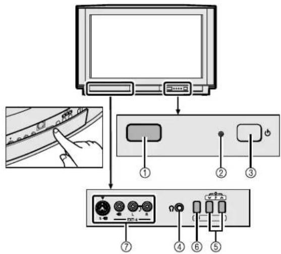

natural_image
Illustration of a hand holding a remote control with an arrow indicating rotation (no text or symbols)FLOF (Fastext)/TOP/WST:
D0005-GE
①Prise de l'antenne (2)
②EXT-1 borne (2, 22, 36)
③EXT-2 borne (2, 5, 22, 36)
④EXT-3 borne (22, 36)
⑤AUDIO OUT borne (sauf AV28CH1EU) (37)
"Q-LINK" (une marque commerciale de Panasonic Corporation)
"Data Logic" (une marque commerciale de Metz Corporation)
"Easy Link" (une marque commerciale de Phillips Corporation)
"Megalogic" (une marque commerciale de Grundig Corporation)
"SMARTLINK" (une marque commerciale de Sony Corporation)

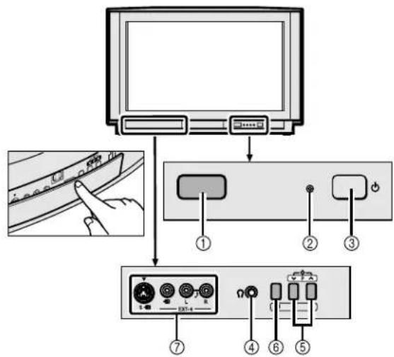
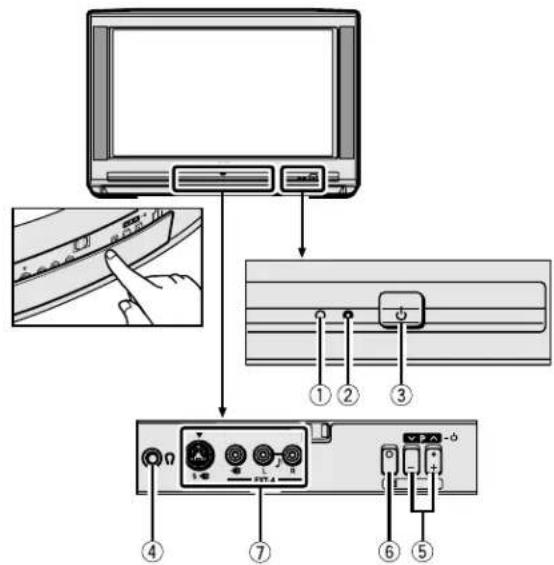
natural_image
Illustration of a hand holding a remote control with an arrow indicating rotation (no text or symbols)FLOF (Fastext)/TOP/WST:
Sélectionner “CH1”, “CH2”, “CC1” ou “CC2”.
| CHARGEMENT TV → VCR |
| TRANSFERT.... |
flowchart
graph TD
    A["Derrière le cache"] --> B["Device with cable ⑨"]
    B --> C["Device with cable ⑪"]
    C --> D["Device with cable ⑫"]
    D --> E["Device with cable ⑬"]
    E --> F["Device with cable ⑭"]
    F --> G["Device with cable ⑮"]
    G --> H["Device with cable ⑰"]
Dos du téléviseur
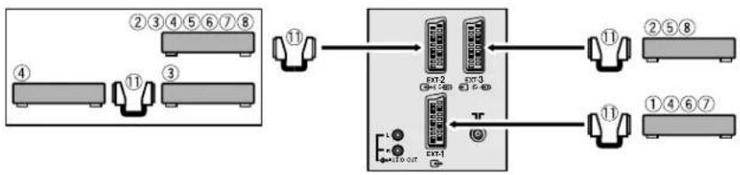
flowchart
graph TD
    A["Port 10"] --> B["EAN2"]
    B --> C["Port 3"]
    C --> D["EAN3"]
    D --> E["Port 11"]
    E --> F["Port 7"]
    G["Port 10"] --> H["EAN4"]
    H --> I["Port 10"]
    style A fill:#f9f,stroke:#333
    style G fill:#f9f,stroke:#333
    style B fill:#ccf,stroke:#333
    style C fill:#ccf,stroke:#333
    style D fill:#ccf,stroke:#333
    style E fill:#ccf,stroke:#333
    style F fill:#ccf,stroke:#333
    style H fill:#ccf,stroke:#333
    style I fill:#ccf,stroke:#333


natural_image
Illustration of a hand holding a remote control with an arrow indicating rotation (no text or symbols)FLOF (Fastext)/TOP/WST:
Kies "CH1", "CH2", "CC1" of "CC2".
1 Schakel de videorecorder in
①Toma de la antena (2)
②Terminal EXT-1 (2, 22, 36)
③Terminal EXT-2 (2, 5, 22, 36)
④Terminal EXT-3 (22, 36)
⑤Terminal AUDIO OUT (excluido AV28CH1EU) (37)

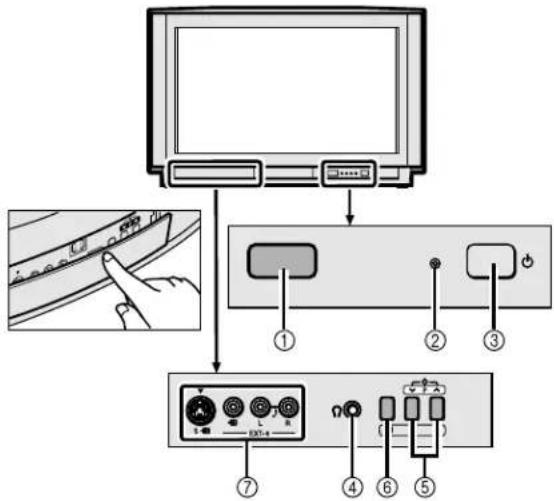

natural_image
Illustration of a hand holding a remote control with an arrow indicating rotation (no text or symbols)FLOF (Fastext)/TOP/WST:
Seleccione “CH1”, “CH2”, “CC1” o “CC2”.
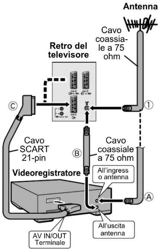
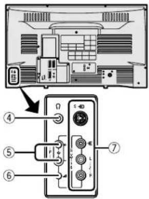


natural_image
Illustration of a hand holding a remote control with an arrow indicating rotation (no text or symbols)FLOF (Fastext), TOP e WST.
FLOF (Fastext)/TOP/WST:
Scegliere “CH1”, “CH2”, “CC1” o “CC2”.
①Tomada da antena (2)
②Terminal EXT-1 (2, 22, 36)
③Terminal EXT-2 (2, 5, 22, 36)
④Terminal EXT-3 (22, 36)
⑤Terminal AUDIO OUT (Excluindo AV28CH1EU) (37)
Colocar as pilhas no controlo remoto


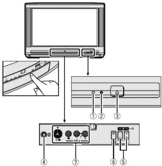
natural_image
Illustration of a hand holding a remote control with an arrow indicating rotation (no text or symbols)FLOF (Fastext), TOP e WST.
FLOF (Fastext)/TOP/WST:
Escolha “CH1”, “CH2”, “CC1” ou “CC2”.
flowchart
graph TD
    A["Monitor"] --> B["USB"]
    B --> C["Audio Cable Interface"]
    C --> D["Audio Cable Interface"]
    D --> E["Audio Cable Interface"]
    E --> F["Audio Cable Interface"]
    F --> G["Audio Cable Interface"]
    G --> H["Audio Cable Interface"]
    H --> I["Audio Cable Interface"]
    I --> J["Audio Cable Interface"]
    J --> K["Audio Cable Interface"]
    K --> L["Audio Cable Interface"]
    L --> M["Audio Cable Interface"]
    M --> N["Audio Cable Interface"]
    N --> O["Audio Cable Interface"]
    O --> P["Audio Cable Interface"]
    P --> Q["Audio Cable Interface"]
    Q --> R["Audio Cable Interface"]
    R --> S["Audio Cable Interface"]
    S --> T["Audio Cable Interface"]
    T --> U["Audio Cable Interface"]
    U --> V["Audio Cable Interface"]
    V --> W["Audio Cable Interface"]
    W --> X["Audio Cable Interface"]
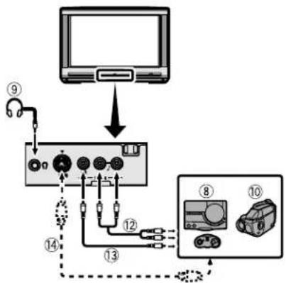
flowchart
graph TD
    A["Monitor"] --> B["Port 1"]
    B --> C["Port 2"]
    C --> D["Port 3"]
    D --> E["Port 4"]
    E --> F["Port 5"]
    F --> G["Port 6"]
    G --> H["Port 7"]
    H --> I["Port 8"]
    I --> J["Port 9"]
    style A fill:#f9f,stroke:#333
    style J fill:#bbf,stroke:#333
Parte traseira do televisor
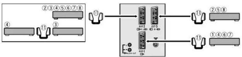
flowchart
graph TD
    A["Module 1"] --> B["External Unit 1"]
    C["Module 2"] --> D["External Unit 2"]
    E["Module 3"] --> F["External Unit 3"]
    G["Module 4"] --> H["External Unit 4"]
    I["Module 5"] --> J["External Unit 5"]
    K["Module 6"] --> L["External Unit 6"]
    M["Module 7"] --> N["External Unit 7"]
    O["Module 8"] --> P["External Unit 8"]
    Q["External Unit 1"] --> R["External Unit 1"]
    S["External Unit 2"] --> T["External Unit 2"]
    U["External Unit 3"] --> V["External Unit 3"]
    W["External Unit 4"] --> X["External Unit 4"]
    Y["External Unit 5"] --> Z["External Unit 5"]
    AA["External Unit 6"] --> AB["External Unit 6"]
    AC["External Unit 7"] --> AD["External Unit 7"]
natural_image
Abstract geometric pattern with diagonal black and white stripes on white background (no text or symbols)JVC
VICTOR COMPANY OF JAPAN, LIMITED


Downloaded from www.Manualslib.com manuals search engine
AV32X25EU/AV28X25EU/AV32H20EU/AV28H20EU/AV28CH1EU
JVC


- WARNING: TO PREVENT FIRE OR SHOCK HAZARD, DO NOT EXPOSE THIS APPLIANCE TO RAIN OR MOISTURE.
- CAUTION:
- Failure to heed the following precautions may result in damage to the TV or remote control.
- CONTENTS
- Setting up your TV
- Caution
- Connecting the aerial and VCR
- ■ Rear Panel
- Connecting the power cord to the AC outlet
- Putting the batteries into the Remote control
- Initial settings
- Press the Main power button on the TV
- Press the OK button
- Press the ◀◀▶ and ▼/▲ buttons to choose ENGLISH. Then press the OK button
- Press the blue button to start the AUTO PROGRAM function
- After the TV channels have been registered in the Programme numbers (PR), the EDIT menu appears
- If "ACI START/ACI SKIP" appears in the AUTO PROGRAM menu:
- Press the OK button to display the T-V LINK menu
- If you do not have a T-V LINK compatible VCR connected:
- If you have a T-V LINK compatible VCR connected to the EXT-2 terminal:
- Now, the initial settings are complete, and you can watch the TV
- T-V LINK FUNCTIONS
- To use T-V LINK functions:
- ■ Pre-set Download
- When "FEATURE NOT AVAILABLE" is displayed:
- ■ Direct Rec
- In the following conditions, the VCR will stop recording if the TV is turned off, if the TV channel or input is switched, or if the menu is displayed on the TV:
- ■ TV Auto Power On/VCR Image View
- TV buttons and functions
- Turn the Main power on
- Press the Main power button on the TV.
- To turn the Main power off:
- Turn the TV on from standby mode
- Choose a TV channel
- Adjust the volume
- Remote control buttons and functions
- Turn the TV on or off from standby mode
- ■ Use the PR LIST:
- Press the ⓘ (Information) button to display the PR LIST
- Press the ◀◀▶ and ▼/▲ buttons to choose a Programme number (PR). Then press the OK button
- Press the ◀/▶ buttons to adjust the volume.
- ■ Muting the sound Press the ⚙ (muting) button to turn off the sound.
- Watch images from external devices
- ■ Use the O(AV) button: Press the O (AV) button to choose an EXT terminal.
- ■ Use the ▼/▲ buttons: Press the ▼/▲ buttons to choose an EXT terminal.
- To return to a TV channel:
- To use the Programme number PR 0 (AV):
- ZOOM function
- AUTO:
- REGULAR:
- PANORAMIC:
- 14:9 ZOOM:
- 16:9 ZOOM:
- 16:9 ZOOM SUBTITLE:
- FULL:
- ■ Choose the ZOOM mode
- Press the ZOOM button to display the ZOOM menu
- Press the ▼▲ buttons to choose a ZOOM mode. Then press the OK button
- ■ Adjusting the visible area of the picture
- Press the ZOOM button
- Press the OK button to display the ZOOM mode indication
- While it is displayed, press the ▼▲▲ buttons to adjust the visible area vertically
- HYPER SOUND function
- Press the ⬇ (HYPER SOUND) button to turn the HYPER SOUND function on or off
- Displaying the current time
- Press the ⓘ (Information) button to display the current time
- Return to TV channel instantly
- Press the TV button
- Operating a JVC brand VCR or DVD player
- Set the VCR 📄 DVD Switch to the VCR or DVD position
- VCR:
- DVD:
- Press the VCR/DVD Control Button to control your VCR or DVD player
- Teletext function
- Basic operation
- Using the List Mode
- ■ To call up a stored page:
- Hold
- Sub-page
- Reveal
- Size
- Index
- Cancel
- Using the TV's menu
- Press the OK button to display the MENU (main menu)
- PICTURE SETTING
- TINT
- COOL:
- WARM:
- NORMAL:
- ■ Picture Adjustment
- CONTRAST:
- BRIGHT:
- SHARP:
- COLOUR:
- HUE:
- To return to the default settings in each TINT mode:
- PICTURE FEATURES
- DIGITAL VNR
- MIN:
- MAX:
- ■ DigiPure Pro (only for AV32X25EU/AV28X25EU)
- DigiPure function:
- Picture motion compensation function:
- Choose DigiPure Pro
- OFF:
- COLOUR SYSTEM
- Choose COLOUR SYSTEM then press the OK button
- PAL:
- SECAM:
- NTSC 3.58:
- NTSC 4.43:
- ■ 4:3 AUTO ASPECT
- Choose 4:3 AUTO ASPECT then press the OK button
- Press the ▼▲ buttons to choose a ZOOM mode
- ■ PICTURE TILT (Excluding AV28CH1EU)
- SOUND SETTING
- ■ STEREO / I • II
- ∞: Stereo sound
- ■ Sound Adjustment
- BASS:
- TREBLE:
- BALANCE:
- BBE
- ON:
- ■ HYPER SOUND
- ■ SPEAKER
- (Excluding AV28CH1EU)
- EXT SETTING
- ■ S-IN (S-VIDEO input)
- Preparation:
- Choose an EXT terminal
- Press the yellow button and set the S-IN (S-VIDEO input).
- Then press the OK button
- To cancel the S-IN (S-VIDEO input) setting:
- ID LIST
- Press the blue button to display the name list (ID LIST)
- Press the ▼▲ buttons to choose a name. Then press the OK button The ID LIST disappears and the name is assigned to the EXT terminal.
- To erase a name assigned to the EXT terminal:
- Press the OK button to complete the setting
- ■ DUBBING
- Press the ◀◀▶ buttons to choose the arrow from the menu
- Press the ▼▲▲ buttons to choose an EXT terminal or TV. Then press the OK button
- EXT-1/EXT-3/EXT-4:
- TV:
- FEATURES
- ■ SLEEP TIMER
- Choose SLEEP TIMER, then press the OK button
- Press the ◀◀▶ buttons to set the period of time.
- To cancel the SLEEP TIMER function:
- BLUE BACK
- CHILD LOCK
- To set the CHILD LOCK function
- Choose CHILD LOCK, then press the 0(AV) button
- Set the ID number to your liking
- Press the OK button
- Press the ▼▲ buttons to choose a TV channel
- Press the blue button and set the CHILD LOCK function.
- To reset the CHILD LOCK function:
- To view a locked TV channel
- Choose a Programme number (PR) in which a TV channel locked with the Number buttons or PR LIST
- Press the Number buttons to enter the ID number
- If you have forgotten the ID number:
- ■ DECODER (EXT-2)
- INSTALL
- LANGUAGE
- Choose LANGUAGE, then press the OK button
- Press the ◀◀▶ and ▼/▲ buttons to choose a language. Then press the OK button
- ■ AUTO PROGRAM
- Choose AUTO PROGRAM. Then press the OK button
- Press the ◀◀▶ and ▼/▲ buttons to choose the country where you are now located
- Press the blue button to start the AUTO PROGRAM function
- After the TV channels have been registered in the Programme numbers (PR), the EDIT menu appears.
- Press the OK button to display the T-V LINK menu
- If you do not have a T-V LINK compatible VCR connected:
- EDIT/MANUAL
- Choose EDIT/MANUAL, then press the OK button
- Follow the operation description of a function you want to use and operate the function
- MOVE:
- ID:
- INSERT:
- DELETE:
- MANUAL:
- Press the OK button to complete the settings
- If you do not have a T-V LINK compatible VCR connected:
- MOVE
- Press the ▼▲ buttons to choose a TV channel
- Press the ▶ button to start the MOVE function
- Press the ▼▲ buttons to choose a new Programme number (PR)
- Press the ◀ button to change the Programme number (PR) of a TV channel to a new Programme number (PR)
- ID
- Press the red button to start the ID function
- Press the ▼▲▲ buttons to choose the first character of a Channel name (ID) you want to attach to the TV channel
- Press the blue button to display the ID LIST (channel name list)
- Press the ▼▲ buttons to choose the Channel name (ID)
- To cancel the ID function:
- Press the OK button to register a Channel name (ID) to a TV channel
- INSERT
- Press the ▼▲ buttons to choose a Programme number (PR) for which you will register a new TV channel
- Press the green button and start the INSERT function.
- Press the ▼▲ buttons to choose "CC" or "CH" according to the CH/ CC number of the TV channel
- Press the Number buttons to enter the remaining CH/CC number
- DELETE
- Press the yellow button to delete the TV channel
- MANUAL
- Press the ▼▲ buttons to choose a Programme number (PR) to which you want to register a new TV channel
- Press the blue button to activate the MANUAL function
- Press the ▶ button to choose the SYSTEM (broadcasting system) for a TV channel you want to register
- Other TV channels:
- Press the green or red button to search for a TV channel
- Press the green or red button repeatedly until the TV channel you want appears
- Press the OK button and register the TV channel to a Programme number (PR)
- Additional menu operations
- Using the ACI function
- Downloading the data to VCR
- Turn on the VCR
- When the T-V LINK menu is changed over to another menu:
- Changing the COUNTRY setting
- Display the INSTALL menu
- When the EDIT menu is currently being displayed:
- Press the ▼▲ buttons to choose AUTO PROGRAM. Then press the OK button
- Using the DECODER (EXT-2) function
- Additional preparation
- Connecting the external devices
- Before connecting anything:
- ■ Devices which can output the S-VIDEO signal (Y/C signal) such as a S-VHS VCR
- ■ T-V LINK compatible VCR
- ■ Connecting headphones
- ■ Video/sound signal output from the EXT-2 terminal
- ■ TV output from the EXT-1 terminal
- ■ Connecting Speakers/Amplifier (Excluding AV28CH1EU)
- CH/CC numbers
- Troubleshooting
- Important:
- ■ If you cannot turn on the TV
- ■ No picture/No sound
- ■ Poor picture
- ■ Poor sound
- ■ Operation disabled
- ■ Other concerns
- Specifications
- Design and specifications subject to change without notice.
- FLOF (Fastext)/TOP/WST:
- Schakel de videorecorder in
- Colocar as pilhas no controlo remoto
- JVC
Brand : JVC
Model : AV28X28EU
Category : Television