
PDP42MXE20 - Television PIONEER - Free user manual and instructions
Find the device manual for free PDP42MXE20 PIONEER in PDF.

| Product type | Plasma display |
| Brand | Pioneer |
| Model | PDP-42MXE20 |
| Native resolution | 1024 x 768 pixels |
| Screen size (diagonal) | 42 inches (105.59 cm) |
| Dimensions (W x H x D) without stand | 1022 x 610 x 98 mm |
| Dimensions (W x H x D) with stand | 1218 x 737 x 300 mm |
| Weight without stand | 30.5 kg |
| Weight with stand | 31.1 kg |
| Power supply | 100 V to 120 V AC, 50/60 Hz |
| Rated current | 3.0 A to 1.3 A |
| Standby power consumption | 1.5 W |
| Video inputs | Analog RGB (D-sub 15-pin), Digital RGB (DVI-D) |
| Audio inputs | 2 x stereo mini-jack |
| Audio output | 1 x stereo mini-jack |
| Built-in speakers power | 8 W + 8 W (6 Ω – 16 Ω) |
| Operating temperature | 0 °C to 40 °C |
| Operating humidity | Less than 85% (unobstructed vents) |
| Main functions | AUTO SETUP, POINT ZOOM, multi-screen, energy saving, ORBITER |
| Included accessories | Power cord, remote control, batteries, cleaning cloth, quick fasteners, cable tie, ferrite cores, screen supports, bolts, instruction manual (CD-ROM) |
| Maintenance and cleaning | Unplug before cleaning. Use a soft dry or slightly damp cloth. Clean the ventilation louvers with a vacuum cleaner once a month. |
| Safety | Do not block vents. Maintain 10 cm above and 5 cm on the sides. Do not expose to moisture. Use a grounded outlet. |
Frequently Asked Questions - PDP42MXE20 PIONEER
User questions about PDP42MXE20 PIONEER
0 question about this device. Answer the ones you know or ask your own.
Ask a new question about this device
Download the instructions for your Television in PDF format for free! Find your manual PDP42MXE20 - PIONEER and take your electronic device back in hand. On this page are published all the documents necessary for the use of your device. PDP42MXE20 by PIONEER.
USER MANUAL PDP42MXE20 PIONEER
This unit has been designed for use as a computer display monitor. The optional video card is required if you wish to view other video signals on the monitor. For details consult your local retail dealer.
Français
Thank you very much for purchasing this PIONEER product. Before using your Plasma Display, please read the "Safety Precautions" and these "Start up Guide" carefully so you will know how to operate the Plasma Display properly. Keep this manual in a safe place. You will find it useful in the future.
Notes on Installation Work:
This product is marketed assuming that it is installed by qualified personnel with enough skill and competence. Always have an installation specialist or your dealer install and set up the product. PIONEER cannot assume liabilities for damage caused by mistake in installation or mounting, misuse, modification or a natural disaster.
Note for Dealers:
After installation, be sure to deliver this manual to the customer and explain to the customer how to handle the product.

If you want to dispose this product, do not mix it with general household waste. There is a separate collection system for used electronic products in accordance with legislation that requires proper treatment, recovery and recycling.
Private households in the 25 member states of the EU, in Switzerland and Norway may return their used electronic products free of charge to designated collection facilities or to a retailer (if you purchase a similar new one).
For countries not mentioned above, please contact your local authorities for the correct method of disposal.
By doing so you will ensure that your disposed product undergoes the necessary treatment, recovery and recycling and thus prevent potential negative effects on the environment and human health.
IMPORTANT

The lightning flash with arrowhead symbol, within an equilateral triangle, is intended to alert the user to the presence of uninsulated "dangerous voltage" within the product's enclosure that may be of sufficient magnitude to constitute a risk of electric shock to persons.
CAUTION
RISK OF ELECTRIC SHOCK DO NOT OPEN
CAUTION:
TO PREVENT THE RISK OF ELECTRIC SHOCK,DO NOT REMOVE COVER (OR BACK).NO USER-SERVICEABLE PARTS INSIDE.REFER SERVICING TO QUALIFIED SERVICE PERSONNEL.

The exclamation point within an equilateral triangle is intended to alert the user to the presence of important operating and maintenance (servicing) instructions in the literature accompanying the appliance.
D3-4-2-1_En-A
WARNING
This equipment is not waterproof. To prevent a fire or shock hazard, do not place any container filed with liquid near this equipment (such as a vase or flower pot) or expose it to dripping, splashing, rain or moisture. D3-4-2-1-3_A_En
WARNING: THIS APPARATUS MUST BE EARTHED.
CAUTION: WHEN POSITIONING THIS EQUIPMENTENSURE THAT THE MAINS PLUG AND SOCKET IS EASILY ACCESSIBLE.
Toensure proper heat radiation, install the unit with the following minimum clearances from other appliances or walls:
10 cm (top), 5 cm (sides and bottom).
Avoid the following installations which will block vents and cause heat to build up inside, resulting in fire hazards.
- Do not attempt to fit the unit inside narrow spaces where ventilation is poor
- Do not place on carpet
- Do not cover with cloth, etc.
- Do not place on its side
- Do not place it upside down
- If planning special installation such as fitting close to the wall, placing it horizontally, etc., be sure to consult your Pioneer dealer first.
WARNING
To prevent a fire hazard, do not place any naked flame sources (such as a lighted candle) on the equipment. D3-4-2-1-7a
D3-4-2-1-7a_A_En
This product complies with the Low Voltage Directive (73/23/EEC, amended by 93/68/EEC), EMC Directives (89/336/EEC, amended by 92/31/EEC and 93/68/EEC). D3-4-2-1-9a_En
CAUTION
The MAIN POWER switch on this unit will not completely shut off all power from the AC outlet. Since the power cord serves as the main disconnect device for the unit, you will need to unplug it from the AC outlet to shut down all power. Therefore, make sure the unit has been installed so that the power cord can be easily unplugged from the AC outlet in case of an accident. To avoid fire hazard, the power cord should also be unplugged from the AC outlet when left unused for a long period of time (for example, when on vacation). D3-4-2-2a A En
The following symbols are found on labels attached to the product. They alert the operators and service personnel of this equipment to any potentially dangerous conditions.
WARNING
This symbol refers to a hazard or unsafe practice which can result in personal injury or property damage.
CAUTION
This symbol refers to a hazard or unsafe practice which can result in severe personal injury or death.
Operating Environment
Operating environment temperature and humidity: +0^ to +40^ (+32^ to +104^) less than 85% RH (cooling vents not blocked)
Do not install this unit in a poorly ventilated area, or in locations exposed to high humidity or direct sunlight (or strong artificial light) D3-4-2-1-7c_A_En
WARNING
Before plugging in for the first time, read the following section carefully.
The voltage of the available power supply differs according to country or region. Be sure that the power supply voltage of the area where this unit will be used meets the required voltage (e.g., 230 V or 120 V) written on the rear panel. D3-4-2-1-4 A En
WARNING
This product equipped with a three-wire grounding (earthed) plug - a plug that has a third (grounding) pin. This plug only fits a grounding-type power outlet. If you are unable to insert the plug into an outlet, contact a licensed electrician to replace the outlet with a properly grounded one. Do not defeat the safety purpose of the grounding plug.
D3-4-2-1-6_A_En
Contents
Safety Precautions
Features 2
Before Proceeding 3
Checking supplied accessories 3
Part Names and Functions 4
Main unit. 4
Remote control unit 5
Connection panel (PDP-60MXE20) 7
Connection panel
(PDP-50MXE20/PDP-50MXE20-S) 8
Connection panel (PDP-42MXE20) 9
Installation and Connections 10
Installation of the unit. 10
Power cord connection. 12
Attaching the ferrite cores. 12
How to route cables 13
Setting the Onscreen Display Language (Computer Signal) 14
Setting the Onscreen Display Language (Video Signal) 15
Additional Information 16
Cleaning 16
Troubleshooting 17
Precautions regarding use 19
STANDBY/ON indicator 19
Specifications 20
CD-ROM (PIONEER PLASMA-UM)
The Operating Instructions are found in the form of a PDF (Portable Document Format) file inside the accessory CD-ROM. To view the file, the use of Adobe Reader is required.
For Windows Users:
1 Place the accessory CD-ROM into your computer's CD-ROM drive.
2 The menu screen should appear automatically.
- If the menu screen does not appear automatically, it can be displayed in the following way:
① Double-click on the [My Computer] icon on your computer's desktop.
② Display the contents of the CD-ROM by double-clicking on the CD-ROM drive where the CD-ROM is loaded.
③ Double-click on the file start_menu.pdf
When the menu appears, continue with step 3 below.
3 When the menu appears, click on the icon corresponding to your Plasma Display's model number.
4 The Operating Instruction PDF file will open.
For Macintosh Users:
1 Place the accessory CD-ROM into your computer's CD-ROM drive.
2 Double-click on the [PIONEER PLASMA-UM] icon on the computer desktop.
3 From the displayed files, double-click on start_menu.pdf.
4 When the menu appears, click on the icon corresponding to your Plasma Display's model number.
5 The Operating Instruction PDF file will open.
To Obtain Adobe Reader:
The use of Adobe Reader is required to view the Operating Instruction manual included on the CD-ROM disc.. To obtain Adobe Reader free of charge, confirm that you are connected to the Internet, then:
1 Click on the [Get Acrobat] icon on the menu screen.
2 Download Adobe Reader from the Adobe download site, and follow the onscreen instructions for installing it on your computer.
Features
- Introduces newly developed Wide Plasma Panel PDP-60MXE20/PDP-50MXE20/PDP-50MXE20-S:
The new wide high-precision plasma panel (1365x768 / 16:9) pushes the envelope of previous high-luminance panels, producing brighter, clearer images with higher contrast.
PDP-42MXE20:
The new wide high-precision plasma panel (1024x768 / 16:9) pushes the envelope of previous high-luminance panels, producing brighter, clearer images with higher contrast.
ES Slot interface for enhanced potential
The display is provided with a built-in ES Slot Interface to allow the installation of cards for the connection of external devices, thus enhancing its expansion potential.
Supports wide range of computer and video signals (analog/digital)
Supports non-compressed display of signals ranging from 640x400 and 640x480 (VGA) to 1024x768 (XGA), and compressed display of 1280x1024 (SXGA), 1400x1050 (SXGA+) and 1600x1200 (UXGA) signals. Further, aspect ratio and screen size settings supported include [DOT BY DOT], [4:3] and [FULL] (*1).
- Supported signals are different on INPUT1 and INPUT2.
*1 Aspect ratio and screen size appearance will differ depending on input signal.
- Free Installation Configuration - Broader installation possibilities with thinner, lighter, high-endurance design
PDP-60MXE20:
While producing a large 60^ screen image, the display is only 122 mm thick, and weighs in at only 62.0kg .
PDP-50MXE20/PDP-50MXE20-S:
While producing a large 50^ screen image, the display is only 99 mm thick, and weighs in at only 35.5kg .
PDP-42MXE20:
While producing a large 42^ screen image, the display is only 98 mm thick, and weighs in at only 30.5kg .
On the other hand, the efficient heat-radiating design greatly improves environmental operating conditions. The thinner, lighter design, coupled to high-endurance construction greatly broadens the range of possible installation locations and styles.
High reliability for commercial applications
This display is provided with features giving it high dependability in commercial applications, including the ability to suppress peak luminance in accordance with the viewing program, and to change the cooling fan's speed in accordance with changes in operating environment. Such features provide safety and high-endurance under conditions of commercial use.
- Improved usability
User convenience has been improved by the inclusion of features making the display even more compatible with your computer. Some of these include the one-touch screen adjustment, [AUTO SET UP] function for computer connections, and the POINT ZOOM function to enlarge local portions of the screen image to display important detailed program data.
Power-Saving Design
The display is provided with a variety of power-saving functions, including an automatic brightness function with ambient light sensor.
- Optional line (sold separately) (For details, please consult the dealer where this unit was purchased.)
1 Table top stand: Display stand.
2 W all installation unit: Wall installation bracket designed as a wall interface for securing the unit.
3 Speaker system designed specifically for Plasma Displays (width: 9 cm): 2-way speaker units featuring 5 cm tweeter and 8 cm woofer in vertical arrangement.
4 Video card: Expansion card allows viewing of video signals and computer analog RGB signals. Cards used in the expansion slots should be manufactured or recommended by Pioneer. Using other expansion cards may result in malfunction.
Checking supplied accessories
Check that the following accessories were supplied.
①Power cord

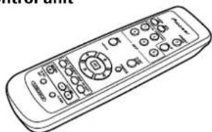
②Remote control unit
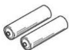
③AA (R6) batteries (x 2)
④ Cleaning cloth (for screen)

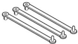
⑤ Speed clamps (x 3)
6Bead band (x 3)

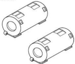
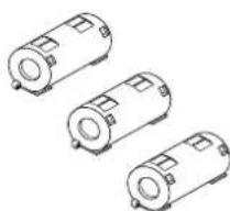
⑦ Ferrite cores (x 3) (for audio cables)

Ferrite core (PDP-60MXE20/PDP-50MXE20/PDP-50MXE20-S: for power cord)

Ferrite cores (x2) (PDP-42MXE20: for power cord)
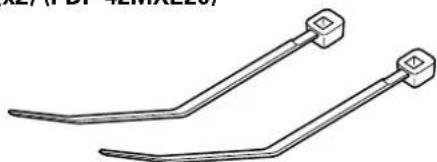
9 Cable tie (PDP-60MXE20/PDP-50MXE20/PDP-50MXE20-S)
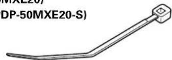
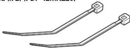
Cable ties (x2) (PDP-42MXE20)
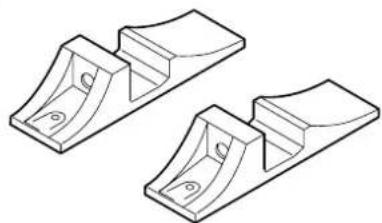
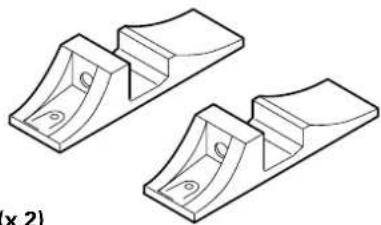
Display stands (x 2) (PDP-42MXE20)
⑪Washers (x 2) (PDP-42MXE20)

12Hex hole bolts (M8 x 40 mm) (x 2) (PDP-42MXE20)

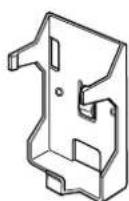
Remote control unit holder (PDP-42MXE20)
Use as a holder for the remote control unit. When attaching to the rear of the main unit, be careful not to cover the vents.
These Operating Instructions (CD-ROM)
- Start up Guide
Warranty
Main unit
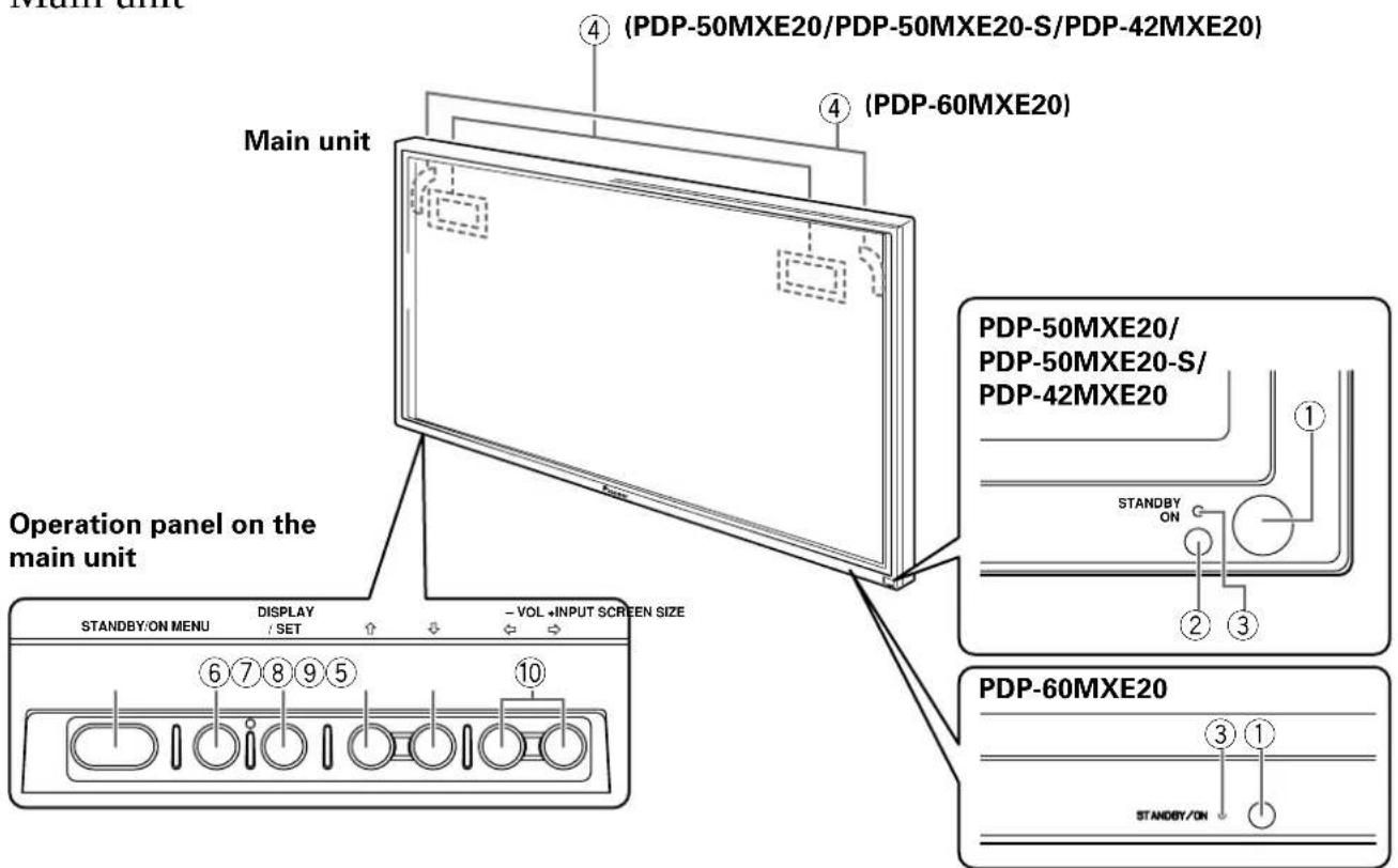
Main unit
① Remote control sensor
Point the remote control toward the remote sensor to operate the unit.
② Ambient light sensor (PDP-50MXE20/PDP- 50MXE20-S/PDP-42MXE20)
This sensor measures the level of light inside the viewing room; it is enabled when the [ENERGY SAVE] option is set to [AUTO].
③ STANDBY/ON indicator
When the unit is operating:
The indicator lights green.
When flashing, the indicator is used to indicate error messages.
The indicator flashes green once every one second when the [POWER MGT.] function is operating.
When the unit is in standby mode:
The indicator lights red.
When flashing, the indicator is used to indicate error messages.
④ Handles
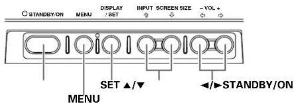
Operation panel on the main unit
⑤ STANDBY/ON button (O)
Press to put the display in operation or standby mode.
6 MENU button
Press to open and close the on-screen menu.
⑦ DISPLAY/SET button
Use to confirm onscreen menu selections, and to change settings.
When not indicated by onscreen menus, used to display the current set status.
⑧ INPUT (↑) button
Except when menu screen is displayed, this button operates to change the input.
⑨ SCREEN SIZE (J) button
Except when menu screen is displayed, this button operates to change the screen size.
10 VOL + / - ( / ) buttons
When not indicated for use in onscreen menu items, these buttons are used for adjusting the sound volume.
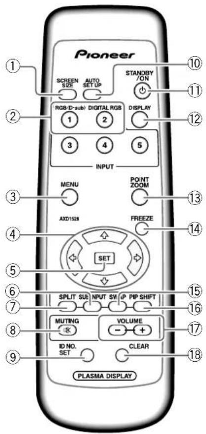
Remote control unit
When handling the remote control unit
- Do not drop the remote control unit or expose it to moisture.
- Do not use the remote control unit in a location subject to direct sunlight, heat radiation from a heater, or in a place subject to excessive humidity.
- When the remote control unit's batteries begin to wear out, the operable distance will gradually become shorter. When this occurs, replace all batteries with new ones as soon as possible.
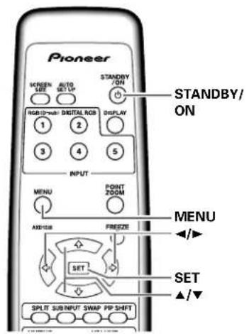
① SCREEN SIZE button Press to select the screen size.
②INPUT buttons Press to select the input.
③ MENU button Press to open and close the on-screen menu.
ADJUST ( / / ) buttons Use to navigate menu screens and to adjust various settings on the unit.
SET button Press to adjust or enter various settings on the unit.
6SUB INPUT button During multi-screen display, use this button to change inputs to subscreens.
⑦SPLIT button Press to switch to multi-screen display.
MUTING button Press to mute the volume.
9ID NO. SET button Button used by professional installers.
10 AUTO SET UP button When using computer signal input, automatically sets the [POSITION], [CLOCK] and [PHASE] to optimum values.
①STANDBY/ON button() Press to put the unit in operation or standby mode.
DISPLAY button Press to view the unit's current input and setup mode.
13POINT ZOOM button Use to select and enlarge one part of the screen.
14 FREEZEButton When memo screen function is enabled, a still image is displayed in the subscreen.
SWAP button During multi-screen display, use this button to switch between main screen and subscreen.
16PIPSHIFT button When using the picture-in-picture mode with multiscreen display, use this button to move the position of subscreen.
VOLUME (+ / - ) buttons Use to adjust the volume.
CLEAR button Button used by professional installers.
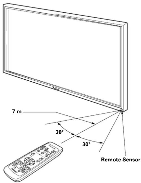
Operating range of the remote control unit
When operating the remote control unit, point it at the remote sensor located on the front panel of the main unit. The remote control unit is operable up to 7m from the unit and within a 30 angle on each side of the sensor.
If you are having difficulty with operation of the remote control unit
The remote control unit may not operate if there are objects placed between it and the display.
- Operational distance will gradually become shorter as the batteries begin to wear out, replace weak batteries with new ones as soon as possible.
This unit discharges infrared rays from the screen. Placing a video deck or other component that is operated by an infrared remote control unit near this unit may hamper that component's reception of the remote control's signal, or prevent it from receiving the signal entirely. Should this occur, move the component to a position further away from this unit.
- Depending on the installation surroundings, this unit's remote control unit may be influenced by the infrared rays discharged from the Plasma Display, hampering reception of its rays or limiting its operational distance. The strength of infrared rays discharged from the screen will differ according to the picture displayed.
Inserting the batteries in the remote control unit
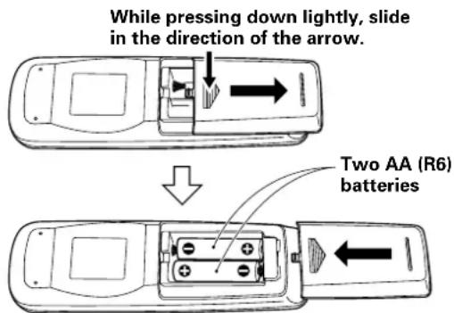
Designated batteries Please use size AA (R6) or AA (LR6).
CAUTION
- Do not use batteries other than those designated, and do not mix old and new batteries together, since rupture or leakage may result, leading to danger of fire, personal injury, or contamination.
- When loading batteries into the remote control unit, insert the batteries with (+) and (-) polarities matching those indicated in the diagram. Inserting batteries incorrectly may result in battery rupture or leakage, leading to danger of fire, personal injury, or contamination.
- Do not heat or disassemble batteries, and do not dispose of batteries in fire or water, since battery rupture or leakage may result, leading to danger of fire or personal injury.
- When not using the remote control unit for extended periods of time, remove the batteries and store them separately. Leaving batteries unused in the unit may result in battery leakage, leading to danger of fire, personal injury, or contamination.
When disposing of used batteries, please comply with governmental regulations or environmental public institution's rules that apply in your country/area. D3-4-2-3-1_En
Connection panel (PDP-60MXE20)
The connection panel is provided with two video input terminals and one video output terminal. Audio input/output and speaker output terminals are also provided.
① COMBINATION IN/OUT
Never connect any component to these connectors without first consulting your Pioneer installation technician.
These connectors are used for Plasma Display setup adjustments.
②SPEAKER (R) terminal
For connection of an external right speaker.
Connect a speaker that has an impedance of 6 Ω to 16 Ω.
③SPEAKER (L) terminal
For connection of an external left speaker. Connect a speaker that has an impedance of 6 Ω to 16 Ω.
4RS-232C
Never connect any component to this connector without first consulting your Pioneer installation technician.
This connector is used for Plasma Display setup adjustments.
⑤ AUDIO (OUTPUT) (Stereo mini jack)
Use to output the audio of the selected source component connected to this unit to an AV amp or similar component.
Note: No sound is produced from the AUDIO (OUTPUT) jack when the MAIN POWER switch is set to OFF or ON (standby).
^ 6 ~ A U D I O ~ ( I N P U T 1 ) ~ ( S t e r e o ~ m i n i ~ j a c k )
Use to obtain sound when INPUT1 is selected. Connect the audio output jack of components connected to INPUT1 to this unit.
Use to obtain sound when INPUT2 is selected.
Connect the audio output jack of components connected to INPUT2 to this unit.
⑧ANALOG RGB OUT (INPUT1) (mini D-sub 15 pin)
Use the ANALOG RGB OUT (INPUT1) terminal to output the video signal to an external monitor or other component.
Note: The video signal will not be output from the ANALOG RGB OUT (INPUT1) terminal when the main power of this unit is off or in standby mode.
ANALOG RGB IN (INPUT1) (mini D-sub 15 pin)
For connection of a personal computer (PC) or similar component. Make sure that the connection made corresponds to the format of the signal output from the connected component.
DIGITAL RGB (INPUT2) (DVI-D jack)
Use to connect a computer.
AC IN
Use to connect the supplied power cord to an AC outlet.
②MAIN POWER switch
Use to switch the main power of the unit on and off.
Connection panel (PDP-50MXE20/PDP-50MXE20-S)
The connection panel is provided with two video input terminals and one video output terminal. Audio input/output and speaker output terminals are also provided.
① SPEAKER (R) terminal
For connection of an external right speaker.
Connect a speaker that has an impedance of 6 to 16
② SPEAKER (L) terminal
For connection of an external left speaker. Connect a speaker that has an impedance of 6 to 16
③ COMBINATION IN/OUT
Never connect any component to these connectors without first consulting your Pioneer installation technician.
These connectors are used for Plasma Display setup adjustments.
4RS-232C
Never connect any component to this connector without first consulting your Pioneer installation technician.
This connector is used for Plasma Display setup adjustments.
⑤AUDIO (OUTPUT) (Stereo mini jack)
Use to output the audio of the selected source component connected to this unit to an AV amplifier or similar component.
Note: No sound is produced from the AUDIO (OUTPUT) jack when the MAIN POWER switch is set to OFF or ON (standby).
AUDIO (INPUT1) (Stereo mini jack)
Use to obtain sound when INPUT1 is selected. Connect the audio output jack of components connected to INPUT1 to this unit.
Use to obtain sound when INPUT2 is selected. Connect the audio output jack of components connected to INPUT2 to this unit.
⑧ANALOG RGB OUT (INPUT1) (mini D-sub 15 pin)
Use the ANALOG RGB OUT (INPUT1) terminal to output the video signal to an external monitor or other component.
Note: The video signal will not be output from the ANALOG RGB OUT (INPUT1) terminal when the main power of this unit is off or in standby mode.
⑨ANALOG RGB IN (INPUT1) (mini D-sub 15 pin)
For connection of a personal computer (PC) or similar component. Make sure that the connection made corresponds to the format of the signal output from the connected component.
DIGITAL RGB (INPUT2) (DVI-D jack)
Use to connect a computer.
1AC IN
Use to connect the supplied power cord to an AC outlet.
12MAIN POWER switch
Use to switch the main power of the unit on and off.
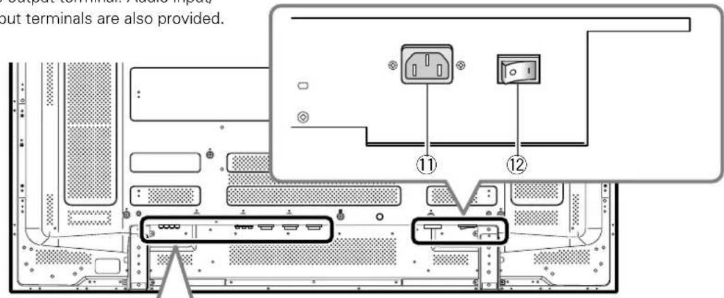
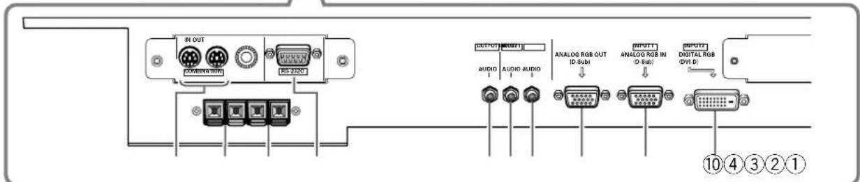
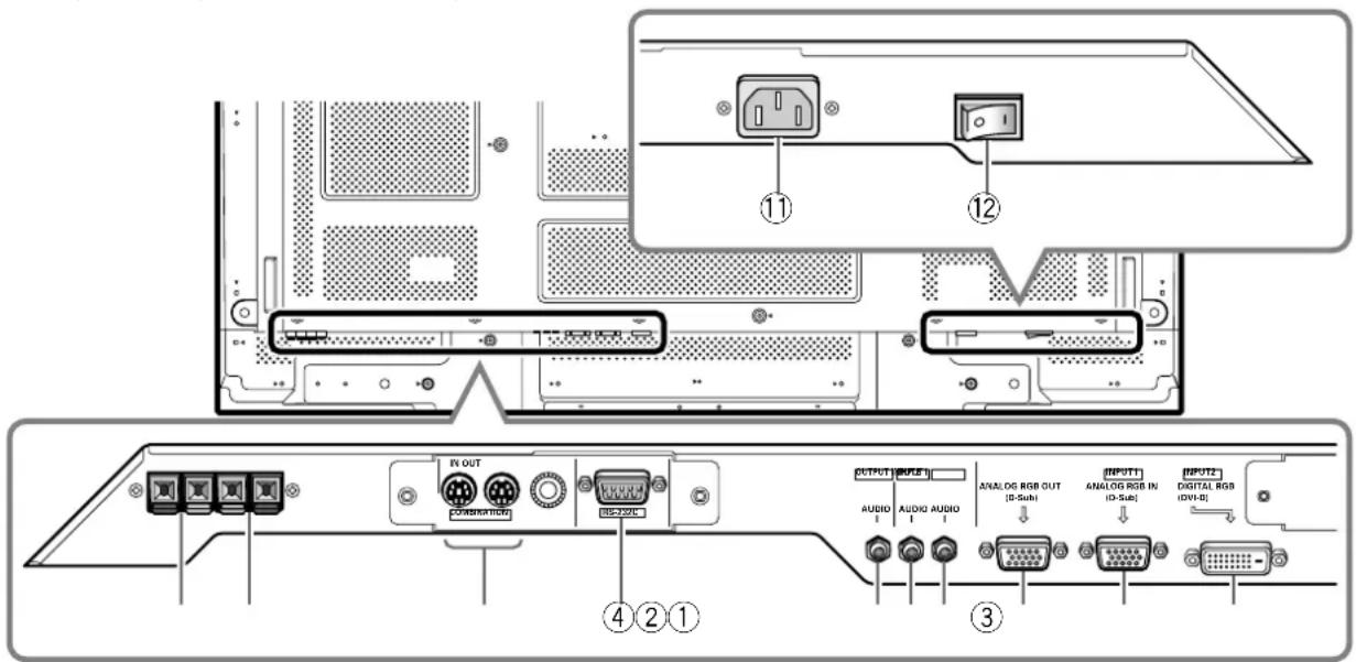
Connection panel (PDP-42MXE20)
The connection panel is provided with two video input terminals and one video output terminal. Audio input/output and speaker output terminals are also provided.
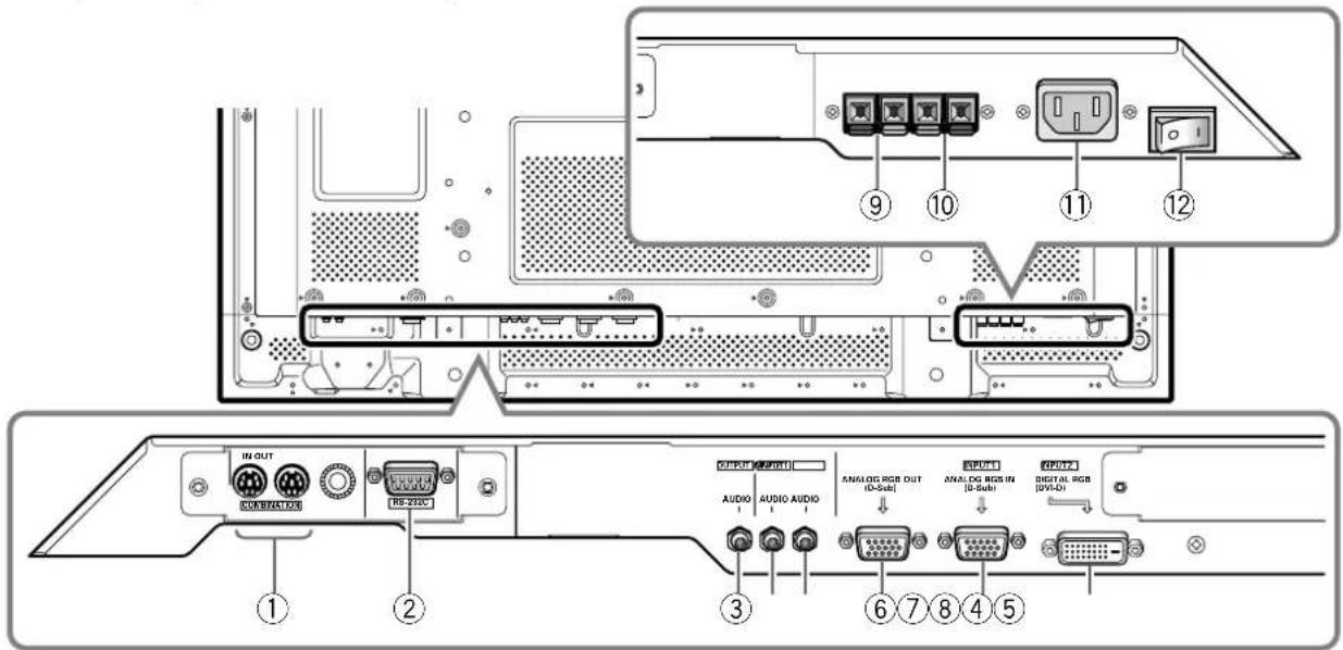
① COMBINATION IN/OUT
Never connect any component to these connectors without first consulting your Pioneer installation technician.
These connectors are used for Plasma Display setup adjustments.
②RS-232C
Never connect any component to this connector without first consulting your Pioneer installation technician.
This connector is used for Plasma Display setup adjustments.
Use to output the audio of the selected source component connected to this unit to an AV amplifier or similar component.
Note: No sound is produced from the AUDIO (OUTPUT) jack when the MAIN POWER switch is set to OFF or ON (standby).
Use to obtain sound when INPUT1 is selected. Connect the audio output jack of components connected to INPUT1 to this unit.
Use to obtain sound when INPUT2 is selected. Connect the audio output jack of components connected to INPUT2 to this unit.
⑥ANALOG RGB OUT (INPUT1) (mini D-sub 15 pin)
Use the ANALOG RGB OUT (INPUT1) terminal to output the video signal to an external monitor or other component.
Note: The video signal will not be output from the ANALOG RGB OUT (INPUT1) terminal when the main power of this unit is off or in standby mode.
⑦ANALOG RGB IN (INPUT1) (mini D-sub 15 pin)
For connection of a personal computer (PC) or similar component. Make sure that the connection made corresponds to the format of the signal output from the connected component.
⑧DIGITAL RGB (INPUT2) (DVI-D jack)
Use to connect a computer.
9SPEAKER (R) terminal
For connection of an external right speaker.
Connect a speaker that has an impedance of 6 to 16Ω.
SPEAKER (L) terminal
For connection of an external left speaker. Connect a speaker that has an impedance of 6 Ω to 16 Ω.
①AC IN
Use to connect the supplied power cord to an AC outlet.
②MAIN POWER switch
Use to switch the main power of the unit on and off.
Installation and Connections
Installation of the unit
Installation using the supplied display stands (PDP-42MXE20)
Be sure to fix the supplied stands to the installation surface. Use commercially available M8 bolts that are 25mm longer than the thickness of the installation surface.
1 Fix the supplied stands to the installation surface at each of the 4 prepared holes using commercially available M8 bolts.
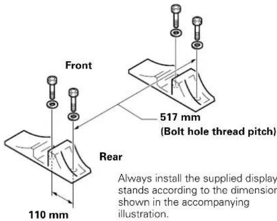

CAUTION
Please be sure to use an M8 (Pitch = 1.25 mm) bolt. (Only this size bolt can be used.)
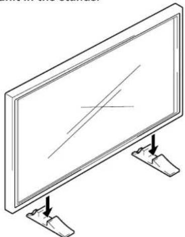
2 Set this unit in the stands.
3 Fix this unit using the supplied washers and hex hole bolts.
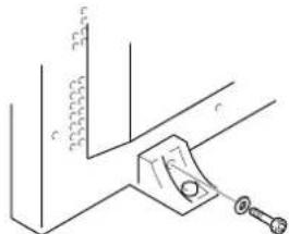
Use a 6 mm hex wrench to bolt them.
Installation using the optional PIONEER stand or other mounting brackets
- Please be sure to request installation or mounting of this unit by an installation specialist or the dealer where purchased.
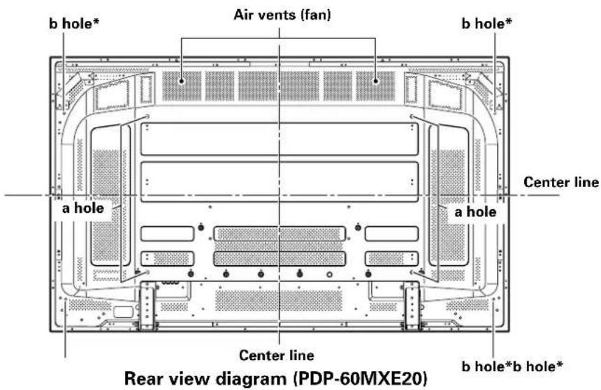
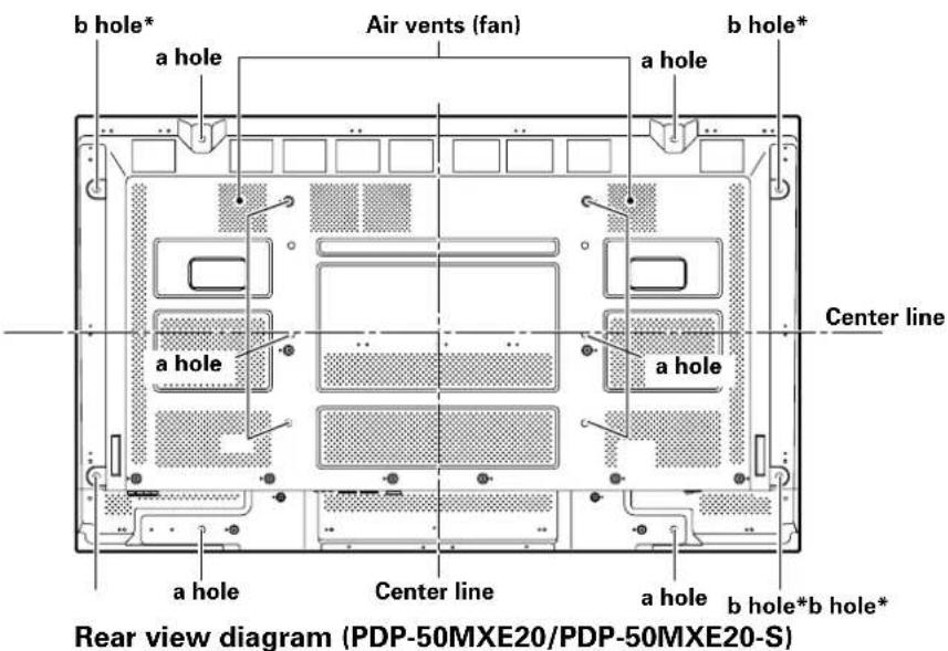
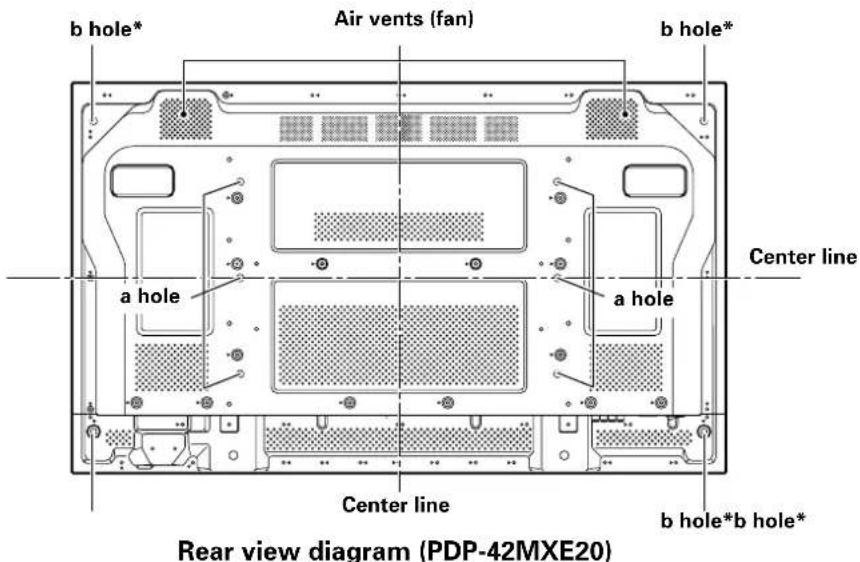
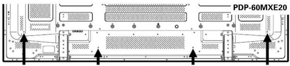
Wall-mount installation of the unit
This unit has been designed with bolt holes for wall-mount installation, etc. The installation holes provided are shown in the accompanying illustration.
- Be sure to attach in 4 or more locations above and below, left and right of the center line.
- Use bolts that are long enough to be inserted 12mm to 18mm into the main unit from the attaching surface for a holes. Refer to the side view diagram in the accompanying illustration.
- As this unit is constructed with glass, be sure to install it on a flat, unwarped surface.

CAUTION
- Use only those stands or mounting brackets designated by Pioneer. If other non-recommended products are used, the unit may fall and be damaged or otherwise malfunction.
- Assemble stands or mounting brackets correctly in accordance with the instructions provided or other applicable installation instructions.
- Two or more people should always work together when installing or removing this unit.
- The installation location selected should be fully capable of supporting the weight of this unit, and be a stable, flat, and even surface. If installed in other locations, the unit may fall or be damage.
After installation, take appropriate measures to prevent the installation from falling. The failure to take such measures could allow the unit to fall, causing injuries or damage. - When this unit is installed on a wall, the work should be done by a professional technician possessing the requisite technical knowledge and abilities; consult your dealer for more information. Improper or insufficient installation may result in accidents, damage or personal injury.
- Handles should not be removed or reattached by anyone other than the professional installation technician or service personnel.
- When moving the display, it should always be carried by two persons holding the rear handles in the manner shown. Never attempt to move the Plasma Display by holding only one of the handles.


Side view diagram

Side view diagram
Side view diagram
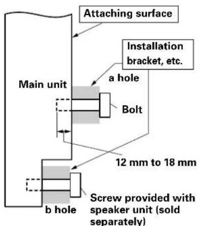
* Only for speaker unit
Power cord connection
Connect the power cord after all component connections have been completed.
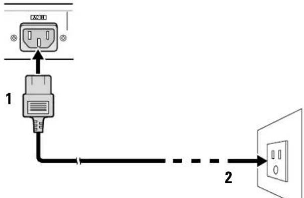
1 Connect the power cord to this unit.
2 Plug the power cord into a power outlet.

CAUTION
- Use only the power cord provided.
For the Plasma Display, use a three-core power cord with a ground terminal.
Always be sure to connect the power cord to a three-pronged grounded outlet and make sure that the cord is properly grounded. If you use a power source converter plug, use an outlet with a ground terminal and screw down the ground line.

NO!
Do not use a power supply voltage other than that indicated (AC 100 V to 240 V, 50 Hz/60 Hz) as this may cause fire or electric shock.
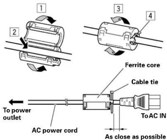
Attaching the ferrite cores
Power cord (PDP-60MXE20/PDP-50MXE20/PDP-50MXE20-S)
Attach the accessory ferrite core to the end of the power cord as shown in the accompanying illustration. Use the provided cable tie to prevent the ferrite core from slipping on the cable.
If you do not do this, this monitor will not conform to mandatory CE or C-Tick standards.
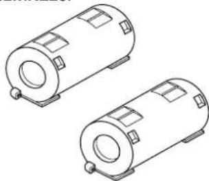
Power cord (PDP-42MXE20)
Attach the accessory ferrite cores to the both connector ends of the power cord as shown in the accompanying illustration. Use the provided cable tie to prevent the ferrite core from slipping on the cable.
If you do not do this, this monitor will not conform to mandatory CE or C-Tick standards.
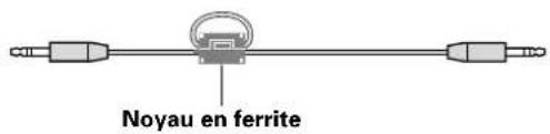
Audio cable
Regarding the audio cable, attach the supplied ferrite core.
Wind the audio cable (not supplied) around the ferrite core once, and then fasten the catch.
If you do not do this, this monitor will not conform to mandatory CE or C-Tick standards.
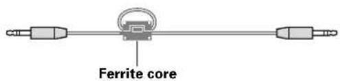
Audio cable (not supplied)
How to route cables
Speed clamps are included with this unit for bunching cables together. Once components are connected, follow the following steps to route cables.
- As viewed from the rear of the display.
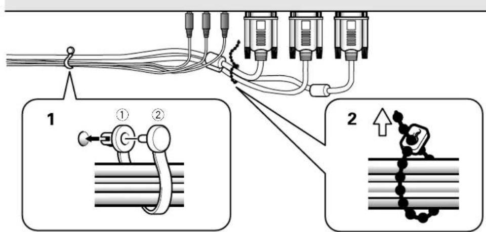
1 Organize cables together using the provided speed clamps.
Insert 1 into an appropriate hole on the rear of the unit, then snap 2 into the back of 1 to fix the clamp. Speed clamps are designed to be difficult to undo once in place. Please attach carefully.
2 Bunch separated cables together and secure them with the provided bead bands.
Do not allow excessive stress to be placed on the ends of cables.
Note
Cables can be routed to the right or left.
- As viewed from the rear of the display.
To attach the speed clamps to the main unit
Connect the speed clamps using the 4 holes marked with "O" below, depending on the situation.
Use the holes marked with the sign as needed.
To remove speed clamps
Using pliers, twist the clamp 90^ and pull it outward. In some cases the clamp may have deteriorated over time and may get damaged when removed.

Setting the Onscreen Display Language (Computer Signal)
The onscreen display language has been set to English as the factory default. To change to another language, the screen setting must be changed. Follow the procedures below to change the setting.
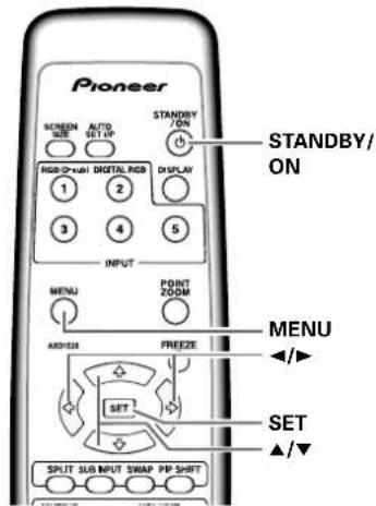
Remote control unit
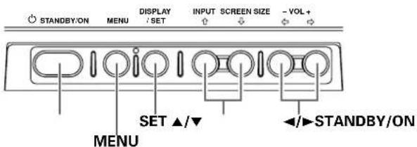
Main unit operating panel
1 Set the rear panel MAIN POWER switch to ON.
The STANDBY/ON indicator on the front panel will light red.
2 Press the STANDBY/ON button to turn the power ON.
The STANDBY/ON indicator on the front panel will light green.
3 Press the MENU button to display the menu screen.
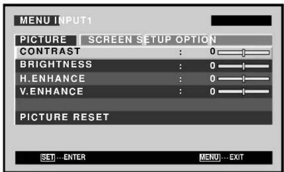
4 Use the buttons to select [OPTION].
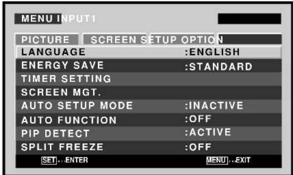
5 Use the / buttons to select [LANGUAGE], then press the SET button.
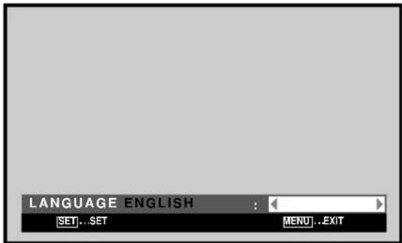
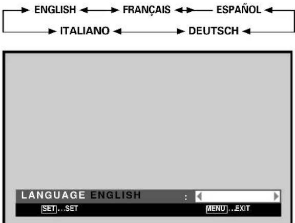
6 Use the / buttons to select the desired language. Each time the / buttons are pressed, the language alternates between those available, in the following order:
7 With the desired language displayed, press the SET button.
The selected language will be set in memory, and the screen will return to that shown in step 4.
8 When settings are completed, press the MENU button to return to the normal screen image.
Note
When the onscreen display language is set for either INPUT1 or INPUT2, the display language for the other input will be set to the same language.
Setting the Onscreen Display Language (Video Signal)
The onscreen display language has been set to English as the factory default. To change to another language, the screen setting must be changed. Follow the procedures below to change the setting.
Remote control unit
Main unit operating panel
1 Set the rear panel MAIN POWER switch to ON.
The STANDBY/ON indicator on the front panel will light red.
2 Press the STANDBY/ON button to turn the power ON.
The STANDBY/ON indicator on the front panel will light green.
3 Press the MENU button to display the menu screen.
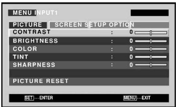
4 Use the buttons to select [OPTION].
![PIONEER PDP42MXE20 - Use the buttons to select [OPTION]. - 1](/content/2026/02/377596/images/55a28d9e58002bf091e438a72737f92f2280b9ef2db58f8c244e57cfaaa8a73f.jpg)
5 Use the / buttons to select [LANGUAGE], then press the SET button.
![PIONEER PDP42MXE20 - Use the / buttons to select [LANGUAGE], then press the SET button. - 1](/content/2026/02/377596/images/5ad5282b87aea888ec81d8a2822959c361e05fafd3cdc9d68832136c28f6cd75.jpg)
6 Use the buttons to select the desired language.
Each time the buttons are pressed, the language alternates between those available, in the following order:

7 With the desired language displayed, press the SET button.
The selected language will be set in memory, and the screen will return to that shown in step 4.
8 When settings are completed, press the MENU button to return to the normal screen image.
Note
When the onscreen display language is set for either INPUT1 or INPUT2, the display language for the other input will be set to the same language.
Cleaning
Regular cleaning will extend the life and performance of this unit. The recommended way to clean the display and related parts is described below.
Before cleaning, be sure to unplug the power cord from the power outlet.
Cleaning the display panel body and remote control
Do not under any circumstances use solvents such as benzine or thinner for cleaner. Use of such liquids may cause deterioration or peeling of paint from the display or remote control unit.
Wipe the display and remote control gently with a soft cloth. In the case of excessive dirt buildup, dampen a soft cloth with a diluted neutral cleaning detergent and after wringing the cloth thoroughly, wipe the component and then dry it with a dry soft cloth.
Cleaning the screen
After dusting, wipe the screen gently using the supplied cleaning cloth or another soft cloth (cotton, flannel, etc.). Do not use tissue or a rough cloth. As the surface of the screen is easily scratched, do not rub it or hit it with a hard object.
If you clean the surface of the screen with a wet cloth, water droplets on the surface may enter into the product, resulting in malfunction.
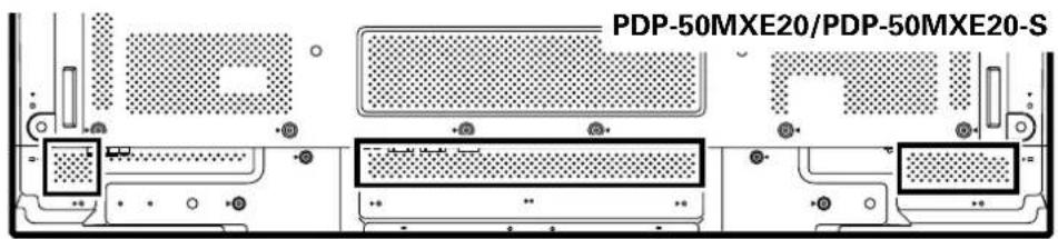
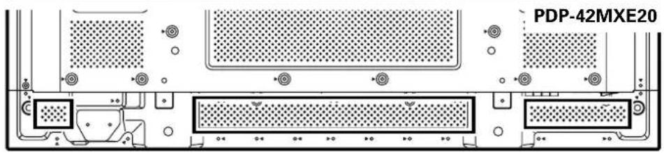
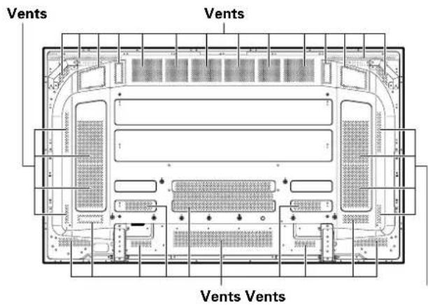
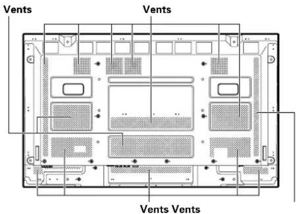
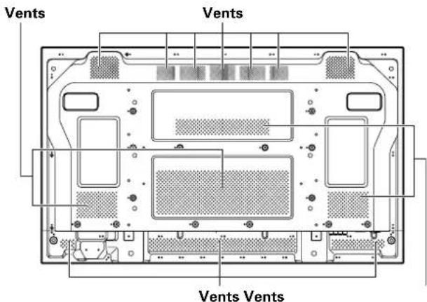
Cleaning the vents
As a general rule, use a vacuum cleaner about once a month to clean the vents on the rear panel of the display of dust buildup (set the vacuum cleaner to its weakest setting when doing this).
Using the unit without cleaning it of dust will cause the internal temperature to increase, resulting in possible breakdown or fire.
PDP-60MXE20
PDP-50MXE20/PDP-50MXE20-S
PDP-42MXE20
Troubleshooting
What may at first seem to be an malfunction, may be remedied with a quick check.
Please check to see if a warning is displayed on the screen. If displayed, refer to the table below and check the mode. If there is no display check to see if the problem is listed on page 18. The problem may also be caused by something other than this unit so please also check the other components being used such as a video deck. If the problem can still not be solved please consult the dealer where this unit was purchased.
About the self diagnosis mode
Messages appear on the bottom of this unit's screen to indicate operation or connection faults. After message confirmation, check the condition of the unit.
| ERRORMESSAGE | REMEDY |
| CAUTIONOUT OF RANGEorCAUTIONUNSUPPORTED SIGNALorSIGNAL NG | The current input signal is not supported by the unit. Check the Computer signal compatibility table and change the computer's output signal setting appropriately. |
| WARNING THERMAL ALERTSHUT DOWN | Turn off main power.Is ambient temperature above 40 °C?Remove any objects blocking the cooling vents on the Plasma Display. |
| WARNING FAN FAILURESHUT DOWN | Cooling fan has malfunctioned. Immediately turn off power, remove power plug from its outlet, and consult a Pioneer service center or your dealer. |
| ERROR INVALID KEY ENTRY | An invalid operation has been attempted. Check input signals, connections and other settings. |
| SHUT DOWN | Turn off main power, wait for 1 to 2 minutes, then try turning power on again. If problem persists, remove power plug from its outlet and consult a Pioneer service center or your dealer. |
General problems
| Problem Possible Solution | |
| • No power. | • Is the power cord disconnected? • Has the MAIN POWER switch been switched on? |
| • Unit cannot be operated. | • External influences such as lightning, static electricity, etc., may cause improper operation. In this case, operate the unit after first turning the MAIN POWER off/on, or unplugging the power cord and re-plugging it in after 1 to 2 minutes. |
| • Remote control does not operate. | • Are batteries inserted with polarity (+,-) correctly aligned? • Are batteries worn out? (Replace with new batteries.) • Is any object occluding the remote signal receiver? • Point the remote control unit toward the remote signal receiver when operating. |
| • Picture is cut off. | • Is the selected screen size correct? Switch to another screen size. • Are [SCREEN] mode adjustments such as picture size made correctly? • Is the POINT ZOOM function being used? |
| • Strange color, light color, or dark, or color misalignment. | • Adjust the picture tone. • Is the room too bright? The picture may look dark in a room that is too bright. |
| • Power is suddenly turned off. | • The unit's internal temperature has increased. (Air vents are blocked.) Remove any objects blocking vent or clean. • Is the [POWER MGT.] function set to [ON]? |
| • No picture. | • Is connection to other components correct? • Has setup been done correctly after connection? • Is the correct input selected? • Is a non-compatible signal being input? • Is the [PICTURE] setting correct? |
Problems commonly mistaken as breakdown
| Problem Possible Solution | |
| The screen is displayed in a small size. | Is the correct screen size selected? |
| Letter breakup on screen. | Adjust using [SCREEN] mode on the menu screen.If there is still no improvement, this unit may be limiting the displayable range. Check the Computer signal compatibility table. |
| A sharp sound is sometimes heard from the cabinet. | Expansion/contraction caused by surrounding temperature change may result in sound being heard from the cabinet. This is not a malfunction. |
| Bright portions of image appear to be losing intensity. | When the video input signal's level is too high, the bright portions may appear to be losing their intensity.Increase the adjustment level of the contrast and check the picture. |
| Speckles or noise appears on screen. | May be caused by radio wave interference from appliances with motors such as hair dryers, electric vacuum cleaners, electric power drills, ignition systems of cars, motorcycles etc., switch devises such as thermostats etc., neon signs or electrical discharge from power lines etc. |
| Stripes appear on the screen. | May be caused by radio wave mingling from TV station, FM station, amateur radios, public radios (simplified radios) etc., or a nearby personal computer, TV, or video/audio component.A strong electromagnetic field may cause picture distortion and similar problems. |
| Sound is heard from inside the unit. | Normal sound of the cooling fan and internal sliding parts of the Plasma Display panel. Not a malfunction. |
| Fan speed changes. | Fan speed changes automatically in accordance with ambient conditions. Not a malfunction. |
| ON (green) indicator doesn't light. | The ON indicator may not light in some cases, depending on the settings performed by the installer. Consult with your installation technician. |
Precautions regarding use
Panel sticking and after-image lag
- Displaying the same images such as still images for a long time may cause after-image lagging. This may occur in the following two cases.
1. After-image lagging due to remaining electrical load
When image patterns with very high peak luminance are displayed for more than 1 minute, after-image lagging may occur due to the remaining electric load. The after-images remaining on the screen will disappear when moving images are displayed. The time for the after-images to disappear depends on the luminance of the still images and the time they had been displayed.
2. After-image (lag image) due to burning
Avoid displaying the same image on the Plasma Display continuously over a long period of time. If the same image is displayed continuously for several hours, or for shorter periods of time over several days, a permanent after-image may remain on the screen due to burning of the fluorescent materials. Such images may become less noticeable if moving images are later displayed, but they will not disappear completely.
The same kind of burning of a lag image may also be produced after extended multi-hour use, or recurrent daily use for shorter periods of a single [4:3] screen size, or [DOT BY DOT] image. Except in cases where violation of intellectual property rights may be involved, it is recommended that lag-image burning be avoided by selecting a screen size that displays images over the entire screen.
- In addition, the [ORBITER] function and [ENERGY SAVE] function can also be used to reduce the chance of lag image formation.
Note
Special precautions must be employed when using the Plasma Display as a surveillance monitor or in other applications where a fixed image will be displayed for extended periods of time. Before using the monitor in such applications, consult your dealer for advice.
When using this unit as a monitor for a surveillance camera, it is recommended to set the [ENERGY SAVE] function to [MODE3] or [MODE2].
About the Plasma Display's protection function
The brightness of this display will deteriorate slightly when an image with little movement such as a photograph or computer image is continuously displayed. This is caused by the Plasma Display's protection function which detects images with slight movement and automatically adjusts brightness to protect the display, and is not a malfunction.
The screen-saver function begins operating when the display detects no or little screen movement for a period of about three minutes; the function is an automatic feature and cannot be turned OFF.
Pixel failure
The Plasma Display screen is composed of a high numbers of tiny pixel elements constructed in a high-precision array, but on occasion one or more of the pixels may fail to light, or may light erratically. This is an inevitable by-product of the manufacturing process and not a malfunction.
Concerning infrared light
In principle, the Plasma Display radiates infrared light. Depending on the environment in which the monitor is installed and used, infrared remote control units for other nearby appliances may fail to operate properly, or noise may be heard in wireless headphones. In such cases, move the affected appliance to a location where its infrared sensor is not affected.
Electromagnetic interference
This unit is built in compliance with official standards for electromagnetic interference, but it nonetheless may produce a low level of radio noise. This noise may be noticeable if AM radios, computers, or video appliances are installed too close to the display. In such cases, remove the affected appliance to a location where it is not affected.
Drive Noise
When power is turned on, some degree of drive noise may be heard; this is normal and not a malfunction.
Plasma Display Temperature
When the display is used for long periods of time, some parts of the display may retain heat and the display may become hot to the touch; this is normal and not a malfunction.
Additional cautions
If the power is automatically turned off during operation of this unit, the following reasons may be the cause. ① Is the [POWER MGT.] function set to [ON]?
The surrounding temperature has risen above 40^ The display should be used within ambient temperature conditions below 40^
③ The internal temperature has risen abnormally due to blocked cooling vents, overheating of internal electronic parts, or other factors.
If the power is automatically turned off for a reason other than the above reasons, there could be a malfunction. In this case, unplug the power cord from the power outlet and request repair from your nearest sales outlet.
- The Plasma Display panel of this unit is very bright and viewing it a close distance will cause eye strain. We recommend that you view the screen from a suitable distance (3 m to 6 m).
- In order to protect the panel and internal circuitry, this display is provided with a cooling fan designed to turn on/off and change speed automatically in accordance with ambient temperature conditions (the fan sound will change in accordance with its speed). The display should be used within ambient temperature conditions below 40^ .
STANDBY/ON indicator
During operation of the [POWER MGT.] function, this indicator will flash green at intervals of about 1 second.
This indicator lights steadily (green) under nominal operating conditions. However, depending on the settings performed by the installation technician, the green indicator may not light even when power is turned on.
If the green light displays a flashing pattern other than the above, an error message is indicated. Consult any onscreen messages and check ambient conditions (temperature, etc.) and respond accordingly.
If the problem persists, disconnect the power plug and consult your dealer or a service center.
Other than this, if the power turns off by itself, or refuses to turn on, or if this indicator conditions flashing red, a malfunction may be indicated. Immediately disconnect the power plug and consult your dealer or a service center. 19
Specifications
General (PDP-60MXE20)
Light emission panel 60V type AC Plasma Panel 131.86 cm (W) x 74.19 cm (H) x 151.3 cm (diagonal)
Number of pixels 1365 x 768
Power supply AC 100 V to 240 V, 50 Hz/60 Hz
Rated current 5.8 A to 2.4 A
Standby power consumption 0.8 W
External dimensions 1470 mm (W) x 880 mm (H) x 122 mm (D)
Weight. 62.0 kg
Operating temperature range. 0^ to 40^
General (PDP-50MXE20/PDP-50MXE20-S)
Light emission panel 50V type AC Plasma Panel 110.36 cm (W) x 62.09 cm (H) x 126.63 cm (diagonal)
Number of pixels 1365 x 768
Power supply AC 100 V to 240 V, 50 Hz/60 Hz
Rated current 3.7 A to 1.5 A
Standby power consumption 0.6 W
External dimensions 1222 mm (W) x 736 mm (H) x 99 mm (D: Not including handles)
Weight. 35.5 kg
Operating temperature range. 0^ to 40^
General (PDP-42MXE20)
Light emission panel 42V type AC Plasma Panel 92.16 cm (W) x 51.53 cm (H) x 105.59 cm (diagonal)
Number of pixels 1024 x 768
Power supply AC 100 V to 240 V, 50 Hz/60 Hz
Rated current 3.0 A to 1.3 A
Standby power consumption 1.5 W
External dimensions 1022 mm (W) x 610 mm (H) x 98 mm (D: Not including handles)
(including display stand) 1218 mm (W) x 737 mm (H) x 300 mm (D)
Weight. 30.5 kg
(including display stand) 31.1 kg
Operating temperature range. 0^ to 40^
Input/output
Video
INPUT1
Input Mini D-sub 15 pin (socket connector) RGB signal (G ON SYNC compatible) RGB ... 0.7 Vp-p/75 Ω/no sync. HD/VS, VD ... TTL level/ positive and negative polarity/ 2.2 kΩ
G ON SYNC
... 1 Vp-p/75 Ω/negative sync.
*Compatible with Microsoft "Plug & Play" (VESA DDC 1/2B)
Output Mini D-sub 15 pin (socket connector) 75Ω/with buffer
INPUT2
Input DVI-D 24-pin connector Digital RGB signal (DVI compliant TMDS signal) *Compatible with Microsoft "Plug & Play" VESA DDC 2B
Audio
Input AUDIO INPUT (for INPUT1)
Stereo mini jack L/R ... 500 mVrms/more than 10k
AUDIO INPUT (for INPUT2)
Stereo mini jack L/R ... 500 mVrms/more than 10k
Output AUDIO OUTPUT
Stereo mini jack L/R ... 500 mVrms (max)/less than 5k
SPEAKER PDP-60MXE20/PDP-50MXE20/ PDP-50MXE20-S L/R ... 6 Ω to 16 Ω/9 W +9 W (at 6 Ω)
PDP-42MXE20 L/R ... 6 Ω to 16 Ω/8 W +8 W (at 6 Ω)
Control
RS-232C ... D-sub 9 pin (pin connector)
COMBINATION IN/OUT ... Mini DIN 6 pin (x2)
Accessories
Power cord 1
Remote control unit 1
AA (R6) batteries 2
Cleaning cloth (for screen) 1
Speed clamps. 3
Bead bands 3
Ferrite cores (for audio cables) 3
Ferrite core (PDP-60MXE20/PDP-50MXE20/PDP-50MXE20-S: for power cord) 1
Ferrite cores (PDP-42MXE20: for power cord) 2
Cable tie (PDP-60MXE20/PDP-50MXE20/ PDP-50MXE20-S) 1
Cable ties (PDP-42MXE20) 2
Display stands (PDP-42MXE20) 2
Washers (PDP-42MXE20) 2
Hex hole bolts (M8 x 40 mm) (PDP-42MXE20) 2
Remote control unit holder (PDP-42MXE20) 1
Operating Instructions (CD-ROM) 1
Start up Guide 1
Warranty. 1
- Due to improvements, specifications and design are subject to change without notice.
Guide de démarrage
Installation et raccordements 10
Installation de I'ecran a plasma 10
⑦ Touche DISPLAY/SET (ecran/validation)
⑧ANALOG RGB OUT (INPUT1)
③ COMBINATION IN/OUT
These prises are used to develop new therapies for the treatment of cancer.
4RS-232C
⑧ANALOG RGB OUT (INPUT1)
① COMBINATION IN/OUT
Cable audio (non fourni)
Menus (Videosignal) 15
Ferritkern (x 2) (PDP-42MXE20:
fürNetzkabel)
9Kabelband (PDP-60MXE20/ PDP-50MXE20/PDP-50MXE20-S)

Kabelband (x 2) (PDP-42MXE20)
Display-Ständer (x 2) (PDP-42MXE20)

1Unterlegscheibe (x 2) (PDP-42MXE20)
Nuclei in ferrite (x 3) (per i cavi audio)
Nuclei in ferrite (x 2)
(PDP-42MXE20:
Nuclei in ferrite (per i cavi audio) 3
① COMBINATION IN/OUT
③ COMBINATION IN/OUT
① COMBINATION IN/OUT
① COMBINATION IN/OUT
②Terminal SPEAKER (R)
Para conectar un altovoz除外. Conecte un altovoz sobre la corda de 6Ω a 16Ω.
③ Terminal SPEAKER (L)
②Terminal SPEAKER (L)
③ COMBINATION IN/OUT
① COMBINATION IN/OUT
Corriente nominal 3,0 a 1,3 A
① COMBINATION IN/OUT
③ COMBINATION IN/OUT
⑩DIGITAL RGB (INPUT2) (DVI-D 插孔)
此插孔用來連接至電腦。
⑪AC IN
① COMBINATION IN/OUT
⑧DIGITAL RGB (INPUT2) (DVI-D 插孔)
此插孔用來連接至電腦。
⑨SPEAKER(R)端子
連接外部右置揚聲器之用。
連接阻抗介於6Ω到16Ω的揚聲器。
10 SPEAKER(L)端子
Printed on recycled paper.
Published by Pioneer Corporation.
Copyright © 2006 Pioneer Corporation.
All rights reserved.
Publication de Pioneer Corporation
© 2006 Pioneer Corporation.
PIONEER EUROPE NV MULTIMEDIA DIVISION Pioneer House Hollybush Hill, Stoke Poges, Slough SL2 4QP, U.K., TEL:44-1753-789-789
PIONEER ELECTRONICS AUSTRALIA PTY.LTD. 178-184, Boundary Road,Braeside, Victoria 3195, Australia, TEL:61-39-586-6300
PIONEER (HK) LIMITED Suite 901-906, 9th Floor World Commerce Centre, Harbour City 11 Canton Road, Tsim Sha Tsui Kowloon, Hong Kong
TEL: 852-2848-6488
PIONEER ELECTRONICS ASIACENTRE, PTE.LTD. 253 Alexandra Road, #04-01, Singapore, 159936, TEL:65-6472-1111
PIONEER GULF FZE Lob 11-017, Jebel Ali Free Zone, P.O.BOX 61226, Jebel Ali, Dubai TEL: 971-4-8815756
PIONEER ELECTRONICS DE MEXICO S.A. DE C.V. Blvd.Manuel Avila Camacho 138 10 piso Col.Lomas de Chapultepec, Mexico.D.F. 11000
TEL:55-9178-4270


- Français
- Notes on Installation Work:
- Note for Dealers:
- IMPORTANT
- CAUTION
- RISK OF ELECTRIC SHOCK DO NOT OPEN
- CAUTION:
- WARNING
- WARNING: THIS APPARATUS MUST BE EARTHED.
- CAUTION: WHEN POSITIONING THIS EQUIPMENTENSURE THAT THE MAINS PLUG AND SOCKET IS EASILY ACCESSIBLE.
- To prevent a fire hazard, do not place any naked flame sources (such as a lighted candle) on the equipment. D3-4-2-1-7a
- Operating Environment
- Contents
- CD-ROM (PIONEER PLASMA-UM)
- For Windows Users:
- For Macintosh Users:
- To Obtain Adobe Reader:
- Features
- - Introduces newly developed Wide Plasma Panel PDP-60MXE20/PDP-50MXE20/PDP-50MXE20-S:
- PDP-42MXE20:
- ES Slot interface for enhanced potential
- Supports wide range of computer and video signals (analog/digital)
- - Free Installation Configuration - Broader installation possibilities with thinner, lighter, high-endurance design
- PDP-60MXE20:
- PDP-50MXE20/PDP-50MXE20-S:
- High reliability for commercial applications
- - Improved usability
- Power-Saving Design
- - Optional line (sold separately) (For details, please consult the dealer where this unit was purchased.)
- Checking supplied accessories
- Main unit
- ① Remote control sensor
- ② Ambient light sensor (PDP-50MXE20/PDP- 50MXE20-S/PDP-42MXE20)
- ③ STANDBY/ON indicator
- ④ Handles
- Operation panel on the main unit
- ⑤ STANDBY/ON button (O)
- MENU button
- ⑦ DISPLAY/SET button
- ⑧ INPUT (↑) button
- ⑨ SCREEN SIZE (J) button
- VOL + / - ( / ) buttons
- Remote control unit
- When handling the remote control unit
- Operating range of the remote control unit
- If you are having difficulty with operation of the remote control unit
- Inserting the batteries in the remote control unit
- Designated batteries Please use size AA (R6) or AA (LR6).
- Connection panel (PDP-60MXE20)
- ① COMBINATION IN/OUT
- ②SPEAKER (R) terminal
- ③SPEAKER (L) terminal
- 4RS-232C
- ⑤ AUDIO (OUTPUT) (Stereo mini jack)
- ^ 6 ~ A U D I O ~ ( I N P U T 1 ) ~ ( S t e r e o ~ m i n i ~ j a c k )
- ⑧ANALOG RGB OUT (INPUT1) (mini D-sub 15 pin)
- ANALOG RGB IN (INPUT1) (mini D-sub 15 pin)
- DIGITAL RGB (INPUT2) (DVI-D jack)
- AC IN
- ②MAIN POWER switch
- Connection panel (PDP-50MXE20/PDP-50MXE20-S)
- ① SPEAKER (R) terminal
- ② SPEAKER (L) terminal
- ③ COMBINATION IN/OUT
- ⑤AUDIO (OUTPUT) (Stereo mini jack)
- AUDIO (INPUT1) (Stereo mini jack)
- ⑨ANALOG RGB IN (INPUT1) (mini D-sub 15 pin)
- 1AC IN
- 12MAIN POWER switch
- Connection panel (PDP-42MXE20)
- ②RS-232C
- ⑥ANALOG RGB OUT (INPUT1) (mini D-sub 15 pin)
- ⑦ANALOG RGB IN (INPUT1) (mini D-sub 15 pin)
- ⑧DIGITAL RGB (INPUT2) (DVI-D jack)
- 9SPEAKER (R) terminal
- SPEAKER (L) terminal
- ①AC IN
- Installation and Connections
- Installation of the unit
- Installation using the supplied display stands (PDP-42MXE20)
- Fix the supplied stands to the installation surface at each of the 4 prepared holes using commercially available M8 bolts.
- Set this unit in the stands.
- Fix this unit using the supplied washers and hex hole bolts.
- Installation using the optional PIONEER stand or other mounting brackets
- Wall-mount installation of the unit
- Power cord connection
- NO!
- Attaching the ferrite cores
- Power cord (PDP-60MXE20/PDP-50MXE20/PDP-50MXE20-S)
- Power cord (PDP-42MXE20)
- Audio cable
- How to route cables
- Organize cables together using the provided speed clamps.
- Bunch separated cables together and secure them with the provided bead bands.
- Note
- To attach the speed clamps to the main unit
- To remove speed clamps
- Setting the Onscreen Display Language (Computer Signal)
- Setting the Onscreen Display Language (Video Signal)
- Set the rear panel MAIN POWER switch to ON.
- Press the STANDBY/ON button to turn the power ON.
- Press the MENU button to display the menu screen.
- Use the buttons to select [OPTION].
- Use the / buttons to select [LANGUAGE], then press the SET button.
- Use the buttons to select the desired language.
- With the desired language displayed, press the SET button.
- When settings are completed, press the MENU button to return to the normal screen image.
- Cleaning
- Cleaning the display panel body and remote control
- Cleaning the screen
- Cleaning the vents
- Troubleshooting
- About the self diagnosis mode
- Precautions regarding use
- Panel sticking and after-image lag
- After-image lagging due to remaining electrical load
- After-image (lag image) due to burning
- About the Plasma Display's protection function
- Pixel failure
- Concerning infrared light
- Electromagnetic interference
- Drive Noise
- Plasma Display Temperature
- Additional cautions
- STANDBY/ON indicator
- Specifications
- General (PDP-60MXE20)
- General (PDP-50MXE20/PDP-50MXE20-S)
- General (PDP-42MXE20)
- Input/output
- Video
- Accessories
- Guide de démarrage
- ⑦ Touche DISPLAY/SET (ecran/validation)
- ⑧ANALOG RGB OUT (INPUT1)
- Menus (Videosignal) 15
- ②Terminal SPEAKER (R)
- ③ Terminal SPEAKER (L)
- ②Terminal SPEAKER (L)
Brand : PIONEER
Model : PDP42MXE20
Category : Television