Moducontrol - Air Conditioning Aermec - Free user manual and instructions
Find the device manual for free Moducontrol Aermec in PDF.

| Product type | Electronic control board for air/water chilled water unit and heat pump |
| Brand | Aermec |
| Model | Moducontrol |
| Display | 4 digits with indicator LEDs (mode, alarm, compressor, stop) |
| User interface | Capacitive keypad (touch keys) |
| Available menus | Readings, User, Installer, Resistance, Alarm history |
| Main functions | Temperature regulation in cooling/heating modes, domestic hot water production, climate compensation, electric heater management |
| Power supply | 230 V ~ 50 Hz (according to IEC EN 60730-1 standards) |
| Communication | Modbus (RS485) via Modu_485A accessory, remote panel PR3 |
| Anti-freeze protection | Configurable: anti-freeze heater, pump, temperature threshold |
| Electrical safety | Compliant with IEC EN 60730-1, IEC EN 61000-6-1/2/3/4, LVD 2006/95/EC and EMC 2004/108/EC directives |
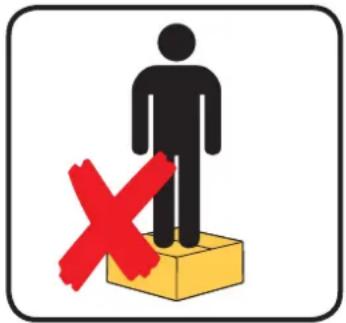
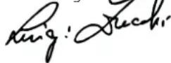
| Maintenance and cleaning | Store in a dry place away from moisture; do not step on packaging |
| Warranty | Does not cover costs of using scaffolding or lifting systems |
| Disposal instructions | Do not dispose of with household waste; deposit at WEEE collection center |
| Operating temperature | Compensation possible from -40 °C to +70 °C (depending on configuration) |
Frequently Asked Questions - Moducontrol Aermec
User questions about Moducontrol Aermec
0 question about this device. Answer the ones you know or ask your own.
Ask a new question about this device
Download the instructions for your Air Conditioning in PDF format for free! Find your manual Moducontrol - Aermec and take your electronic device back in hand. On this page are published all the documents necessary for the use of your device. Moducontrol by Aermec.
USER MANUAL Moducontrol Aermec
natural_image
Weather warning symbol with a red X sign over a box, no text or numbers presentNON calpestare l'imballo
natural_image
Symbolic representation of a person standing on a yellow box with a red X mark, no text or labels present.natural_image
Illustration of two gloves, one white and one black, overlapping without any text or symbols.| Unità | ANL | 0 | 7 | 5 | 4 | 5 | 5 | 0 | 1 | 2 | 1 | 8 | 7 | 3 | 0 | 4 | ||
| ANLI | 0 | 7 | 5 | 4 | 5 | 5 | 0 | 1 | 2 | 1 | 8 | 7 | 3 | 0 | 4 | |||
| ANR | 0 | 7 | 5 | 4 | 5 | 5 | 0 | 1 | 2 | 1 | 8 | 7 | 3 | 0 | 4 | |||
| ANF | 0 | 7 | 5 | 4 | 5 | 5 | 0 | 1 | 2 | 1 | 8 | 7 | 3 | 0 | 4 | |||
| ANK | 0 | 7 | 5 | 4 | 5 | 5 | 0 | 1 | 2 | 1 | 8 | 7 | 3 | 0 | 4 | |||
| SRPV1 | 1 | --- | --- | 65 | 5 | 0 | 12 | 18 | 7 | 30 | 45 | 0 | 35 | 18 | 50 | 10 | ||
| SRA | 1 | --- | --- | 65 | 5 | 0 | 12 | 18 | 7 | 30 | 45 | 0 | 35 | 18 | 50 | 10 | ||
| WRL | --- 7 | 5 --- --- | 0 12 | 18 7 | 30 --- | --- --- --- | --- --- | |||||||||||
- Menù SET (tasto (D) Fig.1)
text_image
A B GET 8 -888 F C D E Fig.1text_image
5 6 7 8 9 1 SET 8 - 88.8 2 3 4 Fig.2text_image
Fig.4 Fig.5 Fig.6
text_image
Hand interacting with a digital display panel showing buttons for power, speaker, and signal icons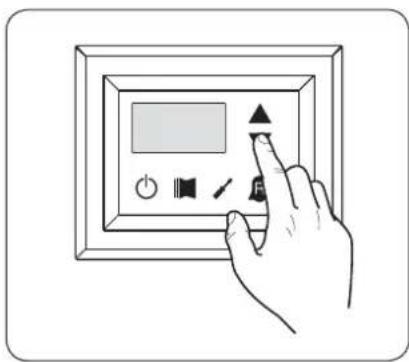
text_image
Hand interacting with a digital display panel showing icons for power, speaker, and function buttonstext_image
Fig.7 Fig.8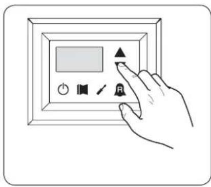
text_image
Hand interacting with a digital display panel showing icons for audio, sound, speaker, and signal controltext_image
Hand interacting with a digital display panel showing icons for power, sound, speaker, and buttontext_image
Hand interacting with a digital display panel showing icons for power, sound, speaker, and buttontext_image
Fig.9a Fig.10a
text_image
Hand interacting with a digital display panel showing icons for power, speaker, and buttontext_image
Fig.9b Fig.10b
text_image
Hand interacting with a digital display panel showing icons for power, speaker, audio, and control buttonstext_image
Fig.14 Fig.15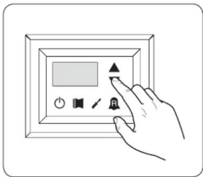
text_image
Hand interacting with a digital display panel showing icons for power, sound, speaker, and buttonEC DECLARATION OF CONFORMITY
We, the undersigned, declare on our own exclusive responsibility that the object in question, so defined:
NAME
MODUCONTROL
TYPE
Electronic card for AIR/WATER chiller, heat pump
And to which this declaration refers, complies with the following standardised regulations:
CEI EN 60730-1
Safety Regulation
CEI EN 61000-6-1
Electromagnetic immunity and emission in residential environment
CEI EN 61000-6-3
CEI EN 61000-6-2
CEI EN 61000-6-4
Electromagnetic immunity and emission in industrial environment
thus meeting the essential requisites of the following directives:
- LV Directive: 2006/95/EC
- Electromagnetic Compatibility Directive 2004/108/EC
Bevilacqua
15/01/2008
Marketing Director
Signature
Precautions and safety regulations ....42
Characteristics of the regulation ....43
USER MENU default settings ....44
ELECTRIC HEATER default settings ....45
INSTALLER MENU default settings 46
INSTALLER MENU 2 default settings ....48
Unit configurations with MODUCONTROL 49
User interface and parameter visualisations ....50
Readings menu 51
ADVANCED READINGS menu 52
USER menu....53
Setting operational parameters (user level) 53
Setting of operational mode (HOT/COLD) 53
Setting of cooling temperature 53
Setting of proportional cooling band 54
Setting heating mode temperature set 54
Setting of proportional heating band 54
Settings made on the basis of outside temperature 54
Setting cooling temperature setpoint 1....55
Setting the outside air temperature 1 55
Setting cooling temperature setpoint 2....55
Setting the outside air temperature 2 55
Setting heating set 1....55
Setting the outside air temperature 1 (heating) 55
Setting heating set 2....56
Setting the outside air temperature 2 (heating) 56
Setting DHW set 56
Setting domestic water proportional band 56
INSTALLER menu....57
Setting operational parameters (installer level) 57
Setting of input and output regulation 57
Setting cooling FORCE-OFF 57
Setting heating FORCE-OFF 58
Setting the safety threshold 58
Setting integral time....58
Setting derivation time 58
Setting the anti-freeze threshold 58
Setting frost protection....58
Setting the supplementary electric heater or activating the boiler ....59
Panel control configuration ....59
Enabling domestic water 59
Power dedicated to domestic water production 60
Standby time in Input/Output 60
Standby time in Input/Output 60
Enabling flow switch bypass 60
Time for flow switch bypass 60
High room temperature standby 61
High temperature threshold for input water 61
Screensaver configuration 61
Modbus supervisor address 61
Supervisor baud rate 61
Supervisor write enabled 61
INSTALLER 2 menu....63
Setting operational parameters (installer level) 63
Threshold for reactivation after shutdown force off 63
Configuration of the heating cable (ANK only) 63
Heating cable setpoint (ANK only) 63
Thermostat pump switch-off 63
INSTALLER 3 menu....64
Setting operational parameters (installer level) 64
Factory settings 64
Setting maximum DCP Volt 64
Managing the electric heater....65
Selection logic for electric heater management mode 65
Supplementary electric heater logic: 65
Replacement electric heater logic: 65
Replacement electric heater logic: 65
ELECTRIC HEATER menu 66
Setting operational parameters (electric heater level) 66
Setting anti-freeze electric heater setpoints 66
Setting anti-freeze electric heater band 66
Setting supplementary electric heater setpoint 67
Setting electric heater band in supplementary/replacement mode 67
Setting outside air temperature threshold for supplementary mode 67
Setting outside air temperature threshold for replacement mode 67
Setting the band for air temperature....67
Table of DIP-SWITCH configuration 68
Alarms summary table....70
Precautions and safety regulations
DO NOT dampen the packaging
text_image
Weather warning sign with red X symbol and cloud, indicating no rain or rain disturbanceDO NOT tread on the packaging

text_image
Warning sign with a human figure and red X symbol on a yellow box, indicating no change or failure.Handle with care

natural_image
Illustration of two gloves, one open and one closed, shown in black and white outlines (no text or symbols)Disposal information
Caution: this product contains electrical and electronic equipment that may not be disposed of through normal municipal rubbish collection channels. There are special centres for the separate collection of this material.
The electrical and electronic apparatus must be treated separately and in accordance with the relevant legislation in force in the country the apparatus is installed in.
Batteries or accumulators in the apparatus must be disposed of separately in accordance with local regulations.
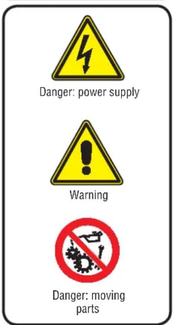
Safety symbols
text_image
Danger: power supply Warning Danger: moving partsNotes regarding the documentation

Store the manuals in a dry location to avoid deterioration, as they must be kept for at least 10 years for any future reference.
Carefully and thoroughly read all the information referred to in this manual. Pay particular attention to the usage instructions accompanied by the words "DANGER" or "WARNING" because, if not observed, they can cause damage to the machine and/or property and/or injury to people. If any kind of malfunction is not included in this manual, contact the local After Sales Service immediately.
The device must be installed in such a way that maintenance and/or repair operations are possible.
The warranty of the device does not in any case cover costs owing to ladder trucks, lifts or other lifting systems that may be required in order to carry out the interventions under guarantee. AERMEC S.p.A. declines all liability for any damage due to improper use of the machine, or the partial or superficial reading of the information contained in this manual.
Characteristics of the regulation
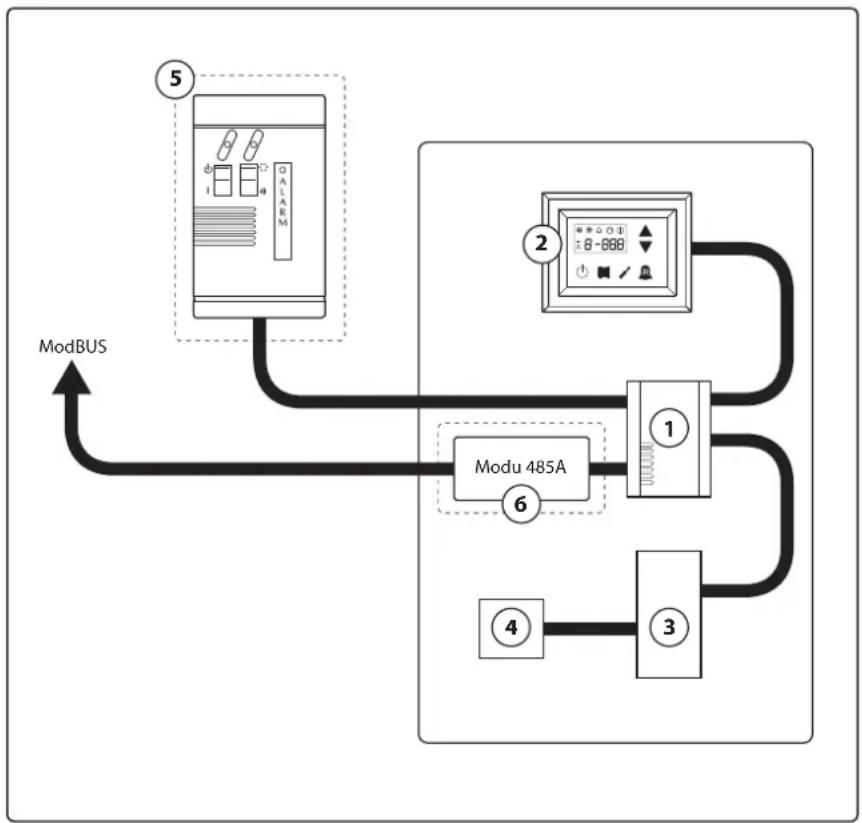
The command panel of the unit allows the rapid setting of the working parameters of the machine, and their visualisation. The display consists of 4 fi gures and various LEDs for indicating the type of operational mode, the visualisation of the parameters set and of any alarms triggered. The card stores all the default settings and any modifications. With the installation of the PR3 remote panel accessory, it is possible to control the switching on and off from a distance, as well as the setting of the operational mode (cooling-heating), and the visualisation of the alarm summary.
Modu_485A adding the accessory, the unit can be managed in a VMF, or be managed via a BMS via Modbus protocol. After the absence of voltage for any period of time, the unit is able to start up again automatically, maintaining the original settings.
flowchart
graph TD
    ModBUS["ModBUS"] --> Modu485A["Modu 485A"]
    Modu485A --> Module1["1"]
    Modu485A --> Module2["2"]
    Modu485A --> Module3["3"]
    Modu485A --> Module4["4"]
    Modu485A --> Modu5["5"]
    Modu485A --> Modu6["6"]
| Index Element Notes | ||
| 1 Moducontrol Board | ||
| 2 Command interface on the machine | ||
| 3 | Board for probes, valves and communication management with inverter module | Present on ANLI units only |
| 4 Board for inverter compressor management Present on ANLI units only | ||
| 5 Simplified remote panel Accessory PR3 | ||
| 6 | ModBus protocol interface board | Modu_485A accessory |
ATTENTION: If you wish to implement a BMS management system, a manual is available on our site www.aermec.com with all specifications necessary for the realisation of a serial supervision system.
USER MENU default settings
USER menu parameters (Password)
| Present on the units | |||||||||||||||||||||||||
| String parameter | StA | StF | bnF | StC | bnC | CSt | SF1 | tF1 | SF2 | tF2 | SC1 | tC1 | SC2 | tC2 | SAS | bAS | |||||||||
| Index parameter | 0 | 1 | 2 | 3 | 4 | 5 | 6 | 7 | 8 | 9 | A | B | C | D | E | F | |||||||||
| Unit | ANL | 0 | 7 | 5 | 4 | 5 | 5 | 0 | 1 | 2 | 1 | 8 | 7 | 3 | 0 | 4 | |||||||||
| ANLI | 0 | 7 | 5 | 4 | 5 | 5 | 0 | 1 | 2 | 1 | 8 | 7 | 3 | 0 | 4 | ||||||||||
| ANR | 0 | 7 | 5 | 4 | 5 | 5 | 0 | 1 | 2 | 1 | 8 | 7 | 3 | 0 | 4 | ||||||||||
| ANF | 0 | 7 | 5 | 4 | 5 | 5 | 0 | 1 | 2 | 1 | 8 | 7 | 3 | 0 | 4 | ||||||||||
| ANK | 0 | 7 | 5 | 4 | 5 | 5 | 0 | 1 | 2 | 1 | 8 | 7 | 3 | 0 | 4 | ||||||||||
| SRPV1 | 1 | --- | --- | 65 | 5 | 0 | 12 | 18 | 7 | 30 | 45 | 0 | 35 | 18 | 50 | 10 | |||||||||
| SRA | 1 | --- | --- | 65 | 5 | 0 | 12 | 18 | 7 | 30 | 45 | 0 | 35 | 18 | 50 | 10 | |||||||||
| WRL | --- | 7 | 5 | --- | 0 | 12 | 18 | 7 | 30 | --- | --- | --- | --- | --- | --- | --- | --- | --- | --- | --- | --- | --- | --- | --- | |


| Functions relative to USER parameters | |||
| Index String | Function | Index String | Function |
| 0 - StA | Operating mode selection | 8 - SF2 | Set at cooling 2 |
| 1 - StF | Set at cooling | 9 - tF2 | Outdoor air temperature (cooling) |
| 2 - bnF | Cooling band | A - SC1 | Set at heating 1 |
| 3 - StC | Set at heating | B - tC1 | Outdoor air temperature 1 (heating) |
| 4 - bnC | Heating band | C - SC2 | Set at heating 2 |
| 5 - CSt | Correction set | D - tC2 | Outdoor air temperature 2 (heating) |
| 6 - SF1 | Set at cooling 1 | E - SAS | DHW Set |
| 7 - tF1 | Outdoor air temperature 1 | F - bAS | DHW Band |
ELECTRIC HEATER default settings
| Electric Heater menu parameters (Password 001) | ||||||||
| Present on the units |  |  |  |  |  |  |  | |
| String parameter | SrA brA | Sri bri tA1 tA2 | bA | |||||
| Index parameter | 0 | 1 | 2 | 3 | 4 | 5 | 6 | |
| Unit | ANL | 4 1 3 4 5 | -30 2 | |||||
| ANLI | 4 1 3 4 5 | -30 2 | ||||||
| ANR | 4 1 3 4 5 | -30 2 | ||||||
| ANF | 4 1 3 4 5 | -30 2 | ||||||
| ANK | 4 1 3 4 5 | -30 2 | ||||||
| SRPV1 | 4 1 3 4 5 | -20 2 | ||||||
| SRA | 4 1 3 4 5 | -20 2 | ||||||
| WRL | 4 1 --- --- --- --- | |||||||
| Unit able to produce hot water (heat pump or heating only unit), in which an integrative electric resist-ance is envisioned | ||||||||
| All units (heat pumps, heating only or cooling only) | ||||||||
| Functions relative to Electric Heater parameters | |||
| Index String | Function | Index String | Function |
| 0 - SrA | Anti-freeze resistance set | 4 - tA1 | Outdoor air set 1 |
| 1 - brA | Anti-freeze resistance band | 5 - tA2 | Outdoor air set 2 |
| 2 - Sri | Integrative resistance set | 6 - bA | Band on air temperature set |
| 3 - bri | Integrative resistance band | ||
INSTALLER MENU default settings
INSTALLER menu parameters (Password 030)
| Present on the units | |||||||||||||||
| String parameter | iu oFF | oFC | SAF | int dE | r AG FrP | rin PAN | ASA | ASP | AAS | trA | |||||
| Index parameter | 0 | 1 | 2 | 3 | 4 | 5 | 6 | 7 | 8 | 9 | A | B | C | D | |
| Unit | ANL 0 | 4 | 54 | 5 | 600 | 0 | 3 | 2 | 0 | 0 | 1 | 70 | 0 | 0 | |
| ANLI | 0 | 4 | 54 | 5 | 600 | 0 | 3 | 2 | 0 | 0 | 1 | 70 | 0 | 0 | |
| ANR | 0 | 4 | 58 | 5 | 600 | 0 | 3 | 2 | 0 | 0 | 1 | 70 | 0 | 0 | |
| ANF 0 | 4 | 54 | 5 | 600 | 0 | 3 | 2 | 0 | 0 | 1 | 70 | 0 | 0 | ||
| ANK | 0 | 4 | 63 | 5 | 600 | 0 | 3 | 2 | 0 | 0 | 1 | 70 | 0 | 0 | |
| SRPV1 | 0 | 4 | 65 | 5 | 600 | 0 | 3 | 2 | 1 | 0 | 1 | 70 | 0 | 2 | |
| SRA | 0 | 4 | 65 | 5 | 600 | 0 | 3 | 2 | 1 | 0 | 1 | 70 | 0 | 2 | |
| WRL | 0 | 4 | --- | 5 | 600 | 0 | 3 | 3 | --- | 0 | --- | --- | --- | --- | |


| Functions relative to INSTALLER parameters | |||
| Index String | Function | Index String | Function |
| 0 - iu | Input/output regulation | 7 - FrP | Frost protection |
| 1 - oFF | Force - off at cooling | 8 - rin | Integration resistance |
| 2 - oFC | Force - off at heating | 9 - PAN | Remote panel configuration |
| 3 - SAF | Force - off rearm band | A - ASA | Enabling DHW |
| 4 - int | Integral time | B - ASP | DHW production power |
| 5 - dEr | Derivative time | C - AAS | Input stand-by time |
| 6 - AG | Anti-freeze | D - trA | Enabling room thermostat |
| INSTALLER menu parameters (Password 030) | ||||||||||||||
| Present on the units | ||||||||||||||
| String parameter | bAF tb | F OAE Ati | SCr Ad1 | Bd1 AS1 | LA1 St1 | LA2 St2 | LSP | |||||||
| Index parameter | E | F | G | H | I | J | L | N | O | P | Q | |||
| Unit | ANL 0 | 180 45 | 64 1 1 1 | 0 -15 43 | -10 58 50 | |||||||||
| ANLI | 0 180 | 45 64 | 1 1 0 -1 | 5 43 -10 | 58 55 | |||||||||
| ANR | 0 180 | 45 64 | 1 1 0 -1 | 5 43 -10 | 58 55 | |||||||||
| ANF 0 | 180 45 | 64 1 1 1 | 0 -15 43 | -10 58 55 | ||||||||||
| ANK | 0 180 | 45 65 | 1 1 0 -2 | 0 53 -10 | 62 60 | |||||||||
| SRPV1 | 0 180 | 45 58 | 0 1 0 -2 | 0 62 -10 | 65 63 | |||||||||
| SRA | 0 180 | 45 58 | 0 1 0 -2 | 0 62 -10 | 65 63 | |||||||||
| WRL | --- --- | --- --- | 1 | 1 1 0 | --- --- --- --- | |||||||||
| Unit able to produce hot water (heat pump water or heating only unit) | ||||||||||||||
| All units (heat pumps, heating only or cooling only) | ||||||||||||||
| Unit that can produce domestic hot water | ||||||||||||||
| INSTALLER menu parameters (Password 030) | ||||||||||||||
| Present on the units | ||||||||||||||
| String parameter | bAF tb F OAE Ati SCr Ad1 Bd1 AS1 LA1 St1 LA2 St2 LSP | |||||||||||||
| Index parameter | E | F | G | H | I | J | L | N | O | P | Q | |||
| Unit | ANL 0 | 180 45 64 1 1 1 0 | -15 43 | -10 58 50 | ||||||||||
| ANLI | 0 180 45 64 1 | 1 1 0 -1 | 5 43 -10 | 58 55 | ||||||||||
| ANR | 0 180 45 64 1 | 1 1 0 -1 | 5 43 -10 | 58 55 | ||||||||||
| ANF 0 | 180 45 64 1 1 1 0 | -15 43 | -10 58 55 | |||||||||||
| ANK | 0 180 45 65 1 | 1 1 0 -2 | 0 53 -10 | 62 60 | ||||||||||
| SRPV1 | 0 180 45 58 0 | 1 1 0 -2 | 0 62 -10 | 65 63 | ||||||||||
| SRA | 0 180 45 58 0 | 1 1 0 -2 | 0 62 -10 | 65 63 | ||||||||||
| WRL | --- --- | --- --- | 1 | 1 1 0 | --- --- --- --- | |||||||||
| Unit able to produce hot water (heat pump water or heating only unit) | ||||||||||||||
| All units (heat pumps, heating only or cooling only) | ||||||||||||||
| Unit that can produce domestic hot water | ||||||||||||||
| Functions relative to INSTALLER parameters | |||
| Index String | Function | Index String | Function |
| E - bAF | Enabling of flow switch by-pass | N - AS1 | Enabling of supervisor writing |
| F - tbF | Flow switch by-pass time | O - LA1 | Air temperature 1 limit |
| G - OAE | Outdoor temperature stand-by | P - St1 | Water temperature 1 limit |
| H - Ati | High temperature return water | Q - LA2 | Air temperature 2 limit |
| I - SCr | Screen saver configuration | R - St2 | Water temperature 2 limit |
| J - Ad1 | Supervisor modbus address | T - LSP | Maximum heating set-point limit that can be set |
| L - Bd1 | Supervisor baudrate | ||
INSTALLER MENU 2 default settings
| INSTALLER 2 menu parameters - (Password 131) | |||||
| Present on the units | |||||
| Index parameter | 0 | 1 | 2 | 3 | |
| Unit | ANL 6 | 0 0 0 | |||
| ANLI 6 | 0 0 0 | ||||
| ANR 6 | 0 0 0 | ||||
| ANF 6 | 0 0 0 | ||||
| ANK | 6 | 0 | 0 | 0 | |
| SRPV1 | 6 | 0 | 0 | 0 | |
| SRA | 6 | 0 | 0 | 0 | |
| WRL | 0 --- --- 0 | ||||
 | Unit able to produce hot water (heat pump water or heating only unit) |
 | All units (heat pumps, heating only or cooling only) |
| Functions relative to INSTALLER 2 menu parameters | |
| Index String | Function |
| 0 | Temperature Delta for reactivation of the compressor after FORCE OFF intervention |
| 1 | Heating cable configuration |
| 2 | Heating cable set-point |
| 3 | Pump switch off for thermostat |
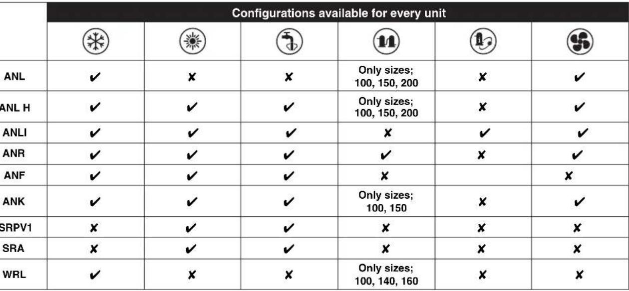
Unit configurations with MODUCONTROL
 |
 |
| √ | Configuration AVAILABLE |
| × | Configuration NOT AVAILABLE |
User interface and parameter visualisations
The main user interface is represented by a LED panel with capacitive keyboard (touch keys); the visualisations are arranged in three menus:
• READINGS menu (key (C) Fig.1)
Containing the information (visualisation mode only) relating to current unit functioning.
- SETTINGS menu (key (D) Fig.1)
Containing all the parameters that the user can modify according to system requirements; these parameters are grouped together in various sub-menus:
- USER menu (Password 000);
- INSTALLER menu (Password 030);
- ELECTRIC HEATER menu (Password 001);
• ALARM log (key (E) Fig.1)
The alarm log records unit error and/or malfunctioning conditions (whether alarms or pre-alarms).
During normal functioning, the monitor visualises the last parameter modified; if no other keys are pressed for at least 5 minutes, the monitor activates the screensaver mode (this function can be set via the parameter (i) in the INSTALLER menu).
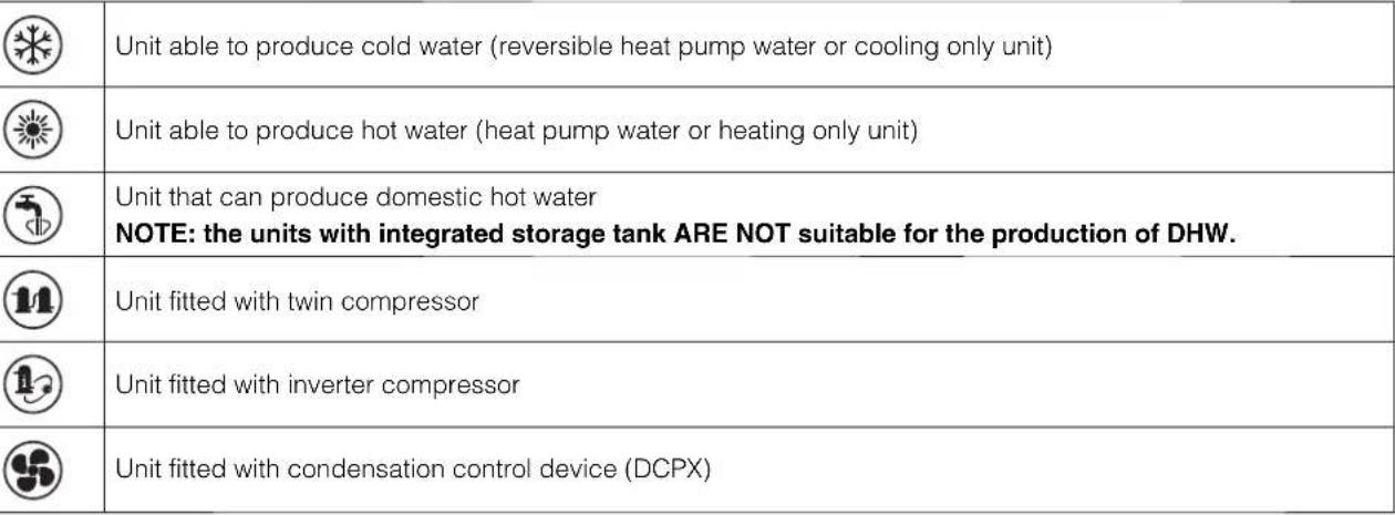
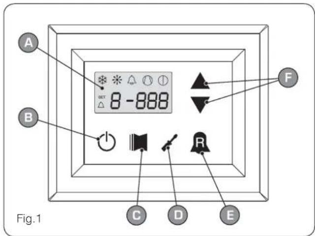
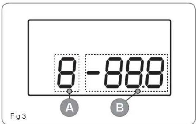
To display parameters and/or readings, 4 fi gures are used; the fi rst is the indicator i.e. a number allowing the user to know which parameter or reading he is visualising (Fig.3).
text_image
A B GET 8 -888 F C D E Fig.1| User interface (Fig.1) | |
| A | Monitor visualisation |
| B | “ON” key |
| C | Key to access readings menu |
| D | Button key to access set menu |
| E | Button key to access alarm record |
| F | Keys to scroll/increase-decrease parameters |
text_image
8 - 88.8 Fig.3 A B| User interface (Fig.3) | |
| A | Parameter index |
| B | Parameter abbreviation / Parameter value |
text_image
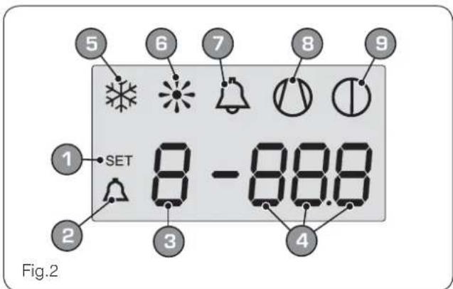
5 6 7 8 9 1 SET 8 - 88.8 2 3 4 Fig.2| Monitor visualisation (Fig.2) | |
| 1 | SETTINGS menu currently visualised |
| 2 | ALARMS menu currently visualised |
| 3 | Parameter index |
| 4 | Parameter abbreviation / Parameter value |
| 5 | Season indicator SUMMER |
| 6 | Season indicator WINTER |
| 7 | Indicator of current alarm status |
| 8 | Indicator of current compressor operational mode(this indication can have different flashing frequencies). |
| 9 | Indicator of stop in progress |
Readings menu
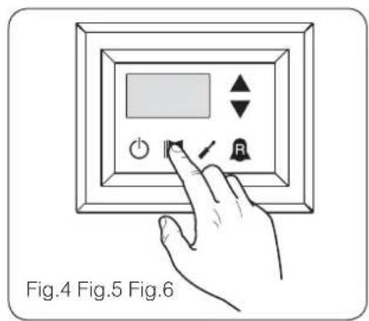
To access the readings menu, press the key in (Fig.4); once the readings menu has been accessed, the monitor will display the readings index and a 3-character string that identifies it; the string will be displayed for one second, after which it is replaced by the value of the reading itself. To move on to the next reading, press the key in (Fig.5); to go back to the previous one, press the key in (Fig.6). Every time you pass from one reading to another, apart from the change in the index value you will also see (for one second) the string identifying
the current reading (it is possible, however, to identify any reading via the value of the indicator, comparing it with the table below).
text_image
Fig.4 Fig.5 Fig.6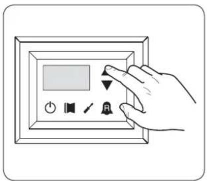
text_image
Hand holding a digital display panel with control buttons including power, speaker, timer, and bell icon
text_image
Diagram showing a hand interacting with a digital display panel, with icons for power, speaker, and function buttons.| Index - String Meaning of the reading | ||
| 0 tUA | Standard | Water output temperature |
| 1 t.A | Standard | Water input temperature |
| 2 tSb | Standard | Coil temperature |
| 3 tGP | Standard | Force gas temperature |
| 4 tRE | ☀️ | Outside air temperature |
| 5 AP | ☀️ | Delivery pressure |
| 6 bP | ☀️ | Suction pressure |
| 7 tEr | Standard | Thermostat |
| 8 SAb | Standard | Safety band on force-off |
| 9 CP | Standard | CP times |
| A HCO | Standard | Hours of operation (thousands) |
| b HCO | Standard | Hours of operation (units) |
| C SPO | Standard | Compressor pickup current(thousands) |
| Standard | Parameter visible on ALL the units |
| Parameter ONLY visible on units suitable for production of hot water |
| Index - String Meaning of the reading | ||
| d SPO | Standard | Compressor pickup current (units) |
| E rEL | Standard | Software release |
| F bld | Standard | Minor software releases |
| G SET | Standard | Setting currently in use |
| H dCP | 5 | DCP pressure setting |
| , dCP | 5 | DCP pressure differential |
| J HCI | 11 | Operating hoursCOMPRESSOR 2 (thousands) |
| L HCI | 11 | Operating hoursCOMPRESSOR 2 (units) |
| N SP I | 11 | Compressor pickup currentCOMPRESSOR 2 (thousands) |
| o SP I | 11 | Compressor pickup currentCOMPRESSOR 2 (units) |
| P Po | 11 | Power fraction |
| 9 rF9 | 12 | Required frequency (INVERTER) |
| r Pr-F | 5 | Pressure drop |
| Parameter ONLY visible on units with condensation control device on board | |
| Parameter ONLY visible on units fitted with twin compressor | |
| Parameter ONLY visible on units fitted with inverter compressor |
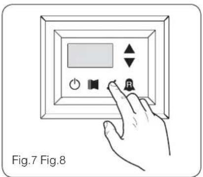
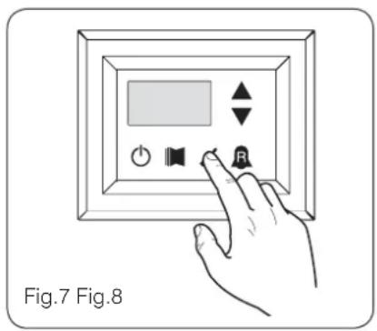
ADVANCED READINGS menu
To enter the ADVANCED READINGS menu, press the key shown in (Fig.7). Once the key has been pressed the password must be inserted for access to the various menus. To access the user menu the password is 010. To modify the value of the password use the arrow keys. Once the correct password has been inserted, press the key shown in (Fig.7). The display shows the index of the reading and a string of three characters that identify it. The string remains
displayed for one second, after which it is replaced by the value relative to the reading itself. To pass to the next reading, use the arrow keys (Fig.8).

PASSWORD = 010
text_image
Fig.7 Fig.8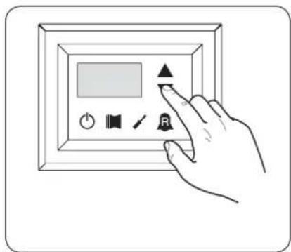
text_image
Hand interacting with a digital display panel showing icons for audio, speaker, and button| Index - String | Reading Meaning Notes | |
| 0 Cor | Inverter Current | Current (in Amperes) measured by the inverter module;Parameter displayed with ANLI 21, 26, 40, 45, 71, 75, 80,100 only; |
| 1 Uo | Inverter output voltage | Output voltage (in Volt) measured by the inverter module;Parameter displayed with ANLI21, 26, 40, 45, 71, 75, 80,100 only; |
| 2 Uob | BUS voltage | BUS voltage (in Volt) measured by the inverter module;Parameter displayed with ANLI21, 26, 40, 45, 71, 75, 80,100 only; |
| 3 HSt | Inverter dissipater temperature | Temperature (in C°) of the inverter module heat dissipater; Parameter displayed with ANL21, 26, 40, 45, 71, 75, 80,100 inverter only; |
| 4 dFo | Value of the dynamic OFF force | Current dynamic ForceOff value calculated on the basis of the outdoor air temperature |
| 5 dHt | DHW remote probe value | Value read by the remote probe positioned in the plant water storage tank; function enabled by the parameter (0) in the INSTALLER menu |
| 6 ASP | Compressor intake probe value | Temperature read from the robe positioned on compressor intake. Parameter displayed only with ANLI 21, 26, 40, 45, 71, 75, 80; |
USER menu
To access the USER menu, press the key in (Fig.7). Once the key has been pressed, you must insert the password to access the various menus; to access the user menu, the password is 000 (displayed by default). To modify the value of the passwords, use the arrow keys. When you have inserted the correct password, press the key in (Fig.7). The monitor will show the index of the USER parameter and a 3-character string that identifies it; the string will be displayed for one second, after which it is replaced by the value of the parameter itself. To move on to the next parameter, use the arrow keys (Fig.8). To modify a pa-
rameter, just select it, press the key in (Fig.7), modify the assigned value using the arrow keys in (Fig.8), and confi rm the modifi cation by pressing the key in (Fig.7) again.

PASSWORD = 000
text_image
Fig.7 Fig.8
text_image
Diagram showing a hand interacting with a digital display panel, featuring icons for power, sound, speaker, and button.Setting operational parameters (user level)
| Setting of operational mode (HOT/COLD) | |||
| Index - String | MIN value | MAX value | Parameter function |
| 0 | 1 | This parameter identifies the functioning mode set for the unit:• set value = 0 - Cooling mode;• set value = 1 - Heating mode.In cooling only units, this parameter is displayed but it cannot be modified.In software versions prior to 3.75, to make the season change the unit must be in standby. | |
| Setting of cooling temperature | |||
| Index - String | MIN value | MAX value | Parameter function |
| 1 SfF | -20 °C | 26 °C | This parameter indicates the value of the work setting active in cooling mode. |
Parameter visible ONLY on units suitable for the production of hot water
Parameter visible ONLY on units suitable for the production of DHW
Parameter visible ONLY on units with condensation control device on board
⑪ Parameter ONLY visible on units fitted with twin compressor
Parameter ONLY visible on units fitted with inverter compressor
| Setting of proportional cooling band | |||
| Index - String | MIN value | MAX value | Parameter function |
| 2 bnF | 1 °C | 20 °C | This parameter indicates the proportional band applied to the cooling set; this band produces the optimised management of the compressor, only switching it on if the inlet/outlet water temperature (depending on the type of control set by parameter (0) in the installer menu) is greater than the cooling work set (parameter (1) user menu) plus the value of this parameter. |
| Setting heating mode temperature set | |||
| Index - string | Value MIN | Value MAX | Parameter function |
| 3 S&C | 25 °C (*) | This parameter indicates the active work set value in the heating mode. This parameter is displayed in the cooling only units but cannot be modified. (*):- the maximum limit can be configured via the parameter (t) of the installer menu;- if the parameter (8) of the installer menu is set at 4, the maximum limit becomes 70°C in order to allow insertion of a set-point for boiler adjustment; | |
| Setting of proportional heating band | |||
| Index - String | MIN value | MAX value | Parameter function |
| 4 bnC | 1 °C | 20 °C | This parameter indicates the proportional band applied to the heating set; this band produces the optimised management of the compressor, only switching it on if the inlet/outlet water temperature (depending on the type of control set by parameter (0) in the installer menu) is less than the healing work set (parameter (3) user menu), minus the value of this parameter. In cooling only units, this parameter is displayed but it cannot be modified. |
| Settings made on the basis of outside temperature | ||||
| Index - String | MIN value | MAX value | Parameter function | |
| 5 CST | 0 | 3 | This setting activates the algorithm of compensation of the work setting: | |
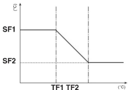 SF1: index (6) user menu;SF2: index (B) user menu;TF1: index (7) user menu;TF2: index (9) user menu;In cooling mode, the work setting is calculated automatically on the basis of the outside temperature, following the logic highlighted in the diagram. SF1: index (6) user menu;SF2: index (B) user menu;TF1: index (7) user menu;TF2: index (9) user menu;In cooling mode, the work setting is calculated automatically on the basis of the outside temperature, following the logic highlighted in the diagram. | 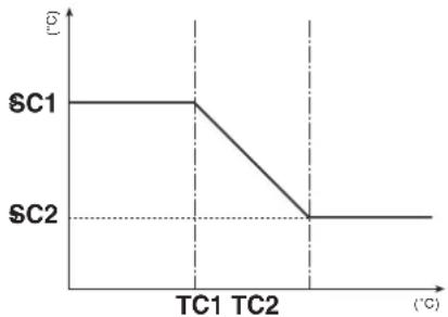 SC1: index (A) user menu;SC2: index (C) user menu;TC1: index (B) user menu;TC2: index (d) user menu;In heating mode, the work setting is calculated automatically on the basis of the outside temperature, following the logic highlighted in the diagram. SC1: index (A) user menu;SC2: index (C) user menu;TC1: index (B) user menu;TC2: index (d) user menu;In heating mode, the work setting is calculated automatically on the basis of the outside temperature, following the logic highlighted in the diagram. | |||

Parameter visible ONLY on units suitable for the production of hot water

Parameter visible ONLY on units with condensation control device on board

Parameter visible ONLY on units suitable for the production of DHW

Parameter ONLY visible on units fitted with twin compressor

Parameter ONLY visible on units fitted with inverter compressor
| Setting cooling temperature setpoint 1 | |||
| Index - String | MIN value | MAX value | Parameter function |
| 6 SF1 | -20 °C | 26 °C | This parameter indicates the maximum value of the cooling setting, corresponding with the minimum outside air temperature (index (7) user menu). This parameter is only visible if the compensation function has been activated (index (5) user menu). |
| Setting the outside air temperature 1 | |||
| Index - String | MIN value | MAX value | Parameter function |
| 7 tF1 | -40 °C | 50 °C | This parameter indicates the minimum outside air temperature taken into consideration for cooling compensation. This parameter is only visible if the compensation function has been activated (index (5) user menu). |
| Setting cooling temperature setpoint 2 | |||
| Index - String | MIN value | MAX value | Parameter function |
| 8 SF2 | -20 °C | 26 °C | This parameter indicates the minimum value of the cooling setting, corresponding with the maximum outside air temperature (index (9) user menu). This parameter is only visible if the compensation function has been activated (index (5) user menu). |
| Setting the outside air temperature 2 | |||
| Index - String | MIN value | MAX value | Parameter function |
| 9 tF2 | -40 °C | 50 °C | This parameter indicates the maximum outside air temperature taken into consideration for cooling compensation. This parameter is only visible if the compensation function has been activated (index (5) user menu). |
| Setting heating set 1 | |||
| Index - string | Value MIN | Value MAX | Parameter function |
| 25 °C (*) | This parameter indicates the maximum value set at heating, in correspondence with the minimum outdoor air temperature (user menu index (b) This parameter is visible only if the compensation function is activated (use menu index (5)).(*):- the maximum limit can be configured via the parameter (t) of the installer menu;- if the parameter (8) of the installer menu is set at 4, the maximum limit becomes 70°C in order to allow insertion of a set-point for boiler adjustment; | ||
| Setting the outside air temperature 1 (heating) | |||
| Index - String | MIN value | MAX value | Parameter function |
| -40 °C | 50 °C | This parameter indicates the minimum outside air temperature taken into consideration for heating compensation. This parameter is only visible if the compensation function has been activated (index (5) user menu). | |
Parameter visible ONLY on units suitable for the production of hot water
Parameter visible ONLY on units suitable for the production of DHW
Parameter visible ONLY on units with condensation control device on board
Parameter ONLY visible on units fitted with twin compressor
Parameter ONLY visible on units fitted with inverter compressor
| Setting heating set 2 | |||
| Index - string | Value MIN | Value MAX | Parameter function |
| 25 °C (*) | This parameter indicates the minimum value set at heating, in correspondence with the maximum outdoor air temperature (user menu index (c) This parameter is visible only if the compensation function is activated (use menu index (5)). (*):- the maximum limit can be configured via the parameter (t) of the installer menu;- if the parameter (8) of the installer menu is set at 4, the maximum limit becomes 70°C in order to allow insertion of a set-point for boiler adjustment; | ||
| Setting the outside air temperature 2 (heating) | |||
| Index - String | MIN value | MAX value | Parameter function |
| -40 °C | 50 °C | This parameter indicates the maximum outside air temperature taken into consideration for heating compensation. This parameter is only visible if the compensation function has been activated (index (5) user menu). | |
| Setting DHW set | |||
| Index - string | Value MIN | Value MAX | Parameter function |
| E SAS | 25 °C (*) | The heat pumps have a work set for the production of DHW; this set indicates the produced water temperature above which the compressor is stopped. Remember that to display this set, the parameter (A) of the installer menu must be active (value set = 1).(*):- the maximum limit can be configured via the parameter (t) of the installer menu;- if the parameter (8) of the installer menu is set at 4, the maximum limit becomes 70°C in order to allow insertion of a set-point for boiler adjustment; | |
| Setting domestic water proportional band | |||
| Index - String | MIN value | MAX value | Parameter function |
| F bAS | 1 °C | 20 °C | This parameter indicates the proportional band applied to the hot domestic water set; this band produces the optimised management of the compressor, only switching it on if the inlet/outlet water temperature (depending on the type of control set by parameter (0) in the installer menu) is less than the hot domestic water set (parameter (E) user menu), minus the value of this parameter. In cooling only units, this parameter is displayed but it cannot be modified. |

Parameter visible ONLY on units suitable for the production of hot water

Parameter visible ONLY on units suitable for the production of DHW

Parameter visible ONLY on units with condensation control device on board

Parameter ONLY visible on units fitted with twin compressor

Parameter ONLY visible on units fitted with inverter compressor
INSTALLER menu
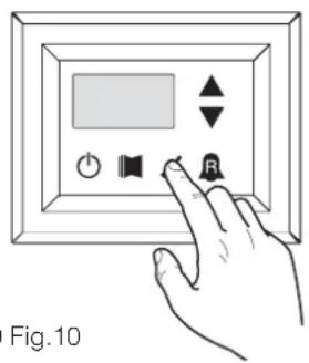
To access the INSTALLER menu, press the key in (Fig.9). Once the key has been pressed, you must insert the password to access the various menus; to access the user menu, the password is 030. To modify the value of the passwords, use the arrow keys. When you have inserted the correct password, press the key in (Fig.9). The monitor will show the index of the INSTALLER parameter and a 3-character string that identifies it; the string will be displayed for one second, after which it is replaced by the value of the parameter itself. To move on to the next parameter, use the arrow keys (Fig.10). To modify a parameter, just se-
lect it, press the key in (Fig.9), modify the assigned value using the arrow keys in (Fig.10), and confirm the modification by pressing the key in (Fig.9) again.
WARNING The following parameters must only be modified by qualified personnel authorised to install the unit.

PASSWORD = 030
text_image
Fig.10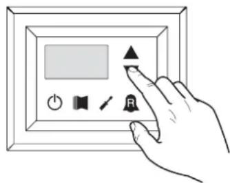
text_image
Hand interacting with a digital display panel showing icons for power, sound, settings, and buttonsSetting operational parameters (installer level)
Setting of input and output regulation
| Index - String | MIN value | MAX value | Parameter function |
| 0 | 2 | The machine adjustment will depend on the value of this parameter:if 0, the machine adjustment is based on the output temperature;if 1, the machine adjustment is based on the input temperature;if 2, the machine adjustment is based on the temperature of the remote probe, as read on the DHW panel (in the event of a fault on the remote probe, the machine adjustment is based on the built-in probe, signalling this fact via alarm code 157).If the production of hot domestic water is activated, the adjustment is automatically forced on the water output temperature, regardless of the value of this parameter. |
Setting cooling FORCE-OFF
| Index - String | MIN value | MAX value | Parameter function |
| 1 OFF | -25 °C | 25 °C | The units check the working temperature (input or output), to which a safety threshold is connected, and beyond which the compressor is switched off immediately and automatically; this threshold is called FORCE-OFF. |

Parameters only visible in heat pump models

Parameters only visible in models set for hot domestic water productio

Parameters only visible in the models with DCP installed

Parameters only visible in bicompressor models

Parameters only visible in the models with inverter compressor
| Setting heating FORCE-OFF | |||
| Index - String | MIN value | MAX value | Parameter function |
| 2 oFC | 30 °C | 70 °C | The heat pumps check the working temperature (input or output), to which a safety threshold is connected, and beyond which the compressor is switched off immediately and automatically; this threshold is called FORCE-OFF. |
| Setting the safety threshold | |||
| Index - String | MIN value | MAX value | Parameter function |
| 3 SAF | 0,5 °C | 20 °C | Temperature threshold above the force-off, which reactivates the start-up of the compressor after the switching off for force-off. |
| Setting integral time | |||
| Index - String | MIN value | MAX value | Parameter function |
| 4 int | 0 s 999 s | The units possess an advanced logic for controlling the processed water temperature; the complete check prevents the system arriving at a point of equilibrium at a higher or lower temperature compared with the one set in the work setting. Remember that an increase in the integration time weakens the effect of the integral control. | |
| Setting derivation time | |||
| Index - String | MIN value | MAX value | Parameter function |
| S dEr | 0 s 12 | 0 s | Time within which the input water temperature is checked to estimate the load on the system; if the band on the setting value is exceeded within this time, the unit will be activated. |
| Setting the anti-freeze threshold | |||
| Index - String | MIN value | MAX value | Parameter function |
| 6 AC | -50 °C | 20 °C | In the units it is possible to set a threshold for the anti-freeze alarm; this value specifies at what temperature the anti-freeze alarm is activated. Remember that, to modify the anti-freeze threshold parameter, the corresponding dip-switch must be activated (see the dip-switch configuration table). |
| Setting frost protection | |||
| Index - String | MIN value | MAX value | Parameter function |
| 7 FrP | 0 | 4 | In the units, it is possible to set a safety control on the water output temperature; on the basis of the value assigned to this parameter, the anti-freeze electric heater is managed as follows:value 0, anti-freeze electric heater absent;value 1, anti-freeze electric heater installed and working only with machine in heat or cool mode;value 2, anti-freeze electric heater installed and working also in standby, but switching on the pump;value 3, anti-freeze electric heater working in standby without the pump being activated;value 4, with external air temperature less than 3^ , the pump is activated for 2 minutes every 30, to monitor the temperature of the water throughout the system. |

Parameters only visible in heat pump models

Parameters only visible in models set for hot domestic water productio

Parameters only visible in the models with DCP installed

Parameters only visible in bicompressor models

Parameters only visible in the models with inverter compressor
Setting the supplementary electric heater or activating the boiler
| Index - String | MIN value | MAX value | Parameter function |
| 8 r in | 0 | 4 | This parameter indicates which logic must be used to manage the supplementary electric heater; the choice of logic is determined by the value set in this parameter so, depending on the value, the settings are:0 = no supplementary electric heater present on the unit1 = supplementary electric heater present, but cannot be activated during hot domestic water production2 = electric heater activation command used as consent for activation of an external boiler3 = supplementary electric heater present and active during hot domestic water production4 = electric heater activation command used as consent for activation of an external boiler which can also be used in supplementary modeWARNING:on the SRP V1 units, it is ABSOLUTELY FORBIDDEN to set this parameter value at (3);to set the value at (4), the DHW accessory is needed. |
Panel control configuration
| Index - String | MIN value | MAX value | Parameter function |
| 9 PAN | 0 | 3 | This setting configures the type of control applicable to the units; depending on the value decided for this setting, the controls on the functioning mode (HEAT/COOL) and the unit on/off command will be managed in the following way:Set value 0:Setting functioning mode = set parameter 0ON/OFF control = from the panel on the machineSet value 1:Setting functioning mode = set parameter 0ON/OFF control = from the remote panelSet value 2:Setting functioning mode = set from remote contactON/OFF control = from the panel on the machineSet value 3:Setting functioning mode = set from remote contactON/OFF control = from the remote contact |
Enabling domestic water
| Index - String | MIN value | MAX value | Parameter function |
| 0 | 1 | In the heat pump models, there is the possibility to produce hot water for domestic use; this production has its own modifiable setting and its own band (parameters E, F user menu); with this parameter you can make parameters E and F visible and usable. Remember that to guide the domestic water production request, once the function has been activated you must use digital input ID6 (marked on the electric card enclosed with the unit as TWS). Remember also that setting this parameter with a value of:• 1, you ENABLE the domestic water function• 0, you DISABLE the domestic water functionThe CLOSED status of the clamp means the domestic water function is ACTIVE. This function is available from software version 3.7 (the software version is visible as a reading, with index E). The minimum compressor functioning time, and the defrosting time, take priority over the production of domestic water. From software version 4.2, when domestic water is activated the adjustment is automatically set on the basis of the output temperature, regardless of the value of the parameter (0) in this menu. |

Parameters only visible in heat pump models

Parameters only visible in models set for hot domestic water productio

Parameters only visible in the models with DCP installed

Parameters only visible in bicompressor models

Parameters only visible in the models with inverter compressor
| Power dedicated to domestic water production | |||
| Index - String | MIN value | MAX value | Parameter function |
| b ASP | 0 % 100 % | In those units that can produce domestic water, once this function has been activated it is possible to decide the percentage of power to use for the production. This function allows you to set a threshold to guarantee reduced energy consumption during domestic water production. | |
| Standby time in Input/Output | |||
| Index - String | MIN value | MAX value | Parameter function |
| C RAS | 0 s 600 s | This parameter allows you to establish the standby time (in seconds) for reversing the 3-way valve inserted in the system for producing domestic water. | |
| Standby time in Input/Output | |||
| Index - String | MIN value | MAX value | Parameter function |
| 0 | 3 | This parameter enables the possibility to join the ID digital clamp (marked on the electric card enclosed with the unit as TRA) with a room thermostat on which the functioning of the compressors and supplementary electric heaters will be disabled.Remember also that setting this parameter with a value of:1 or 2, you ENABLE this function0 or 3, you DISABLE this functionRemember that the OPEN status of the clamp means:the function blocks the compressors and electric heaters if the parameter is set at 1the function blocks the compressors, pump and electric heaters if the parameter is set at 2the pump alarm (as in the previous software version), if the parameter is set at 3Remember also that by setting this parameter at 3, the moducontrol card is compatible with the previous software version (3.6). | |
| Enabling flow switch bypass | |||
| Index - String | MIN value | MAX value | Parameter function |
| E bAF | 0 | 1 | In those units that produce domestic water, the flow switch alarm can be bypassed to allow the correct synchronisation between a diverting valve installed in the system, and unit functioning during the production of hot domestic water. |
| Time for flow switch bypass | |||
| Index - String | MIN value | MAX value | Parameter function |
| F tbF | 0 s 300 s | This parameter allows you to establish the time (in seconds) for flow switch bypass. | |

Parameters only visible in model set for hot water production

Parameters only visible in models set for hot domestic water production

Parameters only visible in the models with DCP installed

Parameters only visible in bicompressor models

Parameters only visible in the models with inverter compressor
| High room temperature standby | |||
| Index - String | MIN value | MAX value | Parameter function |
| 0 | 70 | This parameter lets you establish the room temperature threshold above which the heat pump is disabled; once the threshold has been exceeded, the compressor and pump are switched off. | |
| High temperature threshold for input water | |||
| Index - String | MIN value | MAX value | Parameter function |
| 40 80 | This parameter indicates the temperature of the input water above which the pump is switched off and a pre-alarm is generated. After the intervention of the pre-alarm, there is a waiting time of 15 minutes before the pump starts up again. After the third intervention, the machine goes into alarm/lockout. Active also with the pump switched off, and the chiller in standby. In the latter case, the alarm is generated. | ||
| Screensaver configuration | |||
| Index - String | MIN value | MAX value | Parameter function |
| , SCr | 0 | 2 | This parameter indicates the configuration of the screensaver:• value 0, screensaver disabled;• value 1, screensaver with visualisation of the dashes (to be used with the control panels with software prior to version 1.3);• value 2, screensaver without visualisation of the dashes (to be used with the control panels with software from version 1.3 onwards). |
| Modbus supervisor address | |||
| Index - String | MIN value | MAX value | Parameter function |
| J Rd I | 0.999 | 9 | This parameter indicates the Modbus address assigned to the supervisor; this address will be used in the communication between supervisor and Moducontrol. |
| Supervisor baud rate | |||
| Index - String | MIN value | MAX value | Parameter function |
| L 8d1 | 0 | 2 | This parameter indicates the speed of communication between supervisor and Moducontrol; this speed is set on the basis of the value selected for this parameter:0 = 9600 bps1 = 19200 bps2 = 38400 bps |
| Supervisor write enabled | |||
| Index - String | MIN value | MAX value | Parameter function |
| n AS1 | 0 | 1 | This parameter enables the write commands for the supervisor; this enablement is set on the basis of the value selected for this parameter:0 = write command disabled1 = write command enabledRemember that the read commands are always active. |

Parameters only visible in model set for hot water production

Parameters only visible in models set for hot domestic water production

Parameters only visible in the models with DCP installed

Parameters only visible in bicompressor models

Parameters only visible in the models with inverter compressor
| Air temperature limit 1(*) | |||
| Index - String | MIN value | MAX value | Parameter function |
| -25°C | 45°C | This parameter indicates the external air temperature at which the machine can produce its maximum water value (this value is specified in parameter P - St1). | |
| Water temperature limit 1(*) | |||
| Index - String | MIN value | MAX value | Parameter function |
| P St I | 0°C 70°C | This parameter indicates the maximum temperature of the water produced, in line with the outside air temperature specified in parameter O - LA1. | |
| Air temperature limit 2(*) | |||
| Index - String | MIN value | MAX value | Parameter function |
| 9 LA2 | -25°C | 45°C | This parameter indicates the external air temperature at which the machine can produce its maximum water value (this value is specified in parameter R - St2). |
| Water temperature limit 2(*) | |||
| Index - String | MIN value | MAX value | Parameter function |
| r St2 | 0°C 70°C | This parameter indicates the maximum temperature of the water produced, in line with the outside air temperature specified in parameter Q - LA2. | |
| Maximum heating set point | |||
| Index - String | MIN value | MAX value | Parameter function |
| t LSP | 15°C | 65°C | This parameter indicates the maximum temperature of the water produced by the unit in heat mode. |

Parameters only visible in model set for hot water production

Parameters only visible in models set for hot domestic water production

Parameters only visible in the models with DCP installed

Parameters only visible in bicompressor models

Parameters only visible in the models with inverter compressor
INSTALLER 2 menu
To access the INSTALLER_2 menu, follow the same procedure described for the INSTALLER menu; the only difference is the value of the password, which is 31.
WARNING The following parameters must only be modified by qualified personnel authorised to install the unit.

PASSWORD = 031
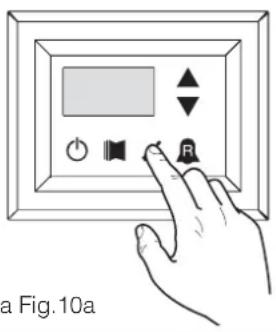
text_image
a Fig.10a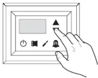
text_image
Hand interacting with a digital display panel showing icons for buttons, speaker, play, and timerFig.9a Fig.10a
Setting operational parameters (installer level)
Threshold for reactivation after shutdown force off
| Index - String | MIN value | MAX value | Parameter function |
| 0 | 0 °C 3 | 0 °C | If the parameter value rin = 4 (parameter 8 of the Installer menu), then this is a probe storage system, this parameter indicates how much lower the threshold of force off so as to prevent the compressor is reactivated after the intervention of ForceOff dynamic extinguished soon after. |
Configuration of the heating cable (ANK only)
| Index - String | MIN value | MAX value | Parameter function |
| 1 | 0 | 2 | Setting the output to which the heating cable is connected:0- no heating cable1- heating cable on the CPA output(the parameter (0) of the menu with password=72 "according to CP must be 0"2- heating cable on the VGC output if not used (the configuration of the dip switches must be: DIP1 = ON, DIP2=ON, DIP5=ON, DIP8=OFF, DIP9=OFF) |
Heating cable setpoint (ANK only)
| Index - String | MIN value | MAX value | Parameter function |
| 2 | -20 °C | 10 °C | Heating cable activated with an external air temperature lower than the value of this parameter.Heating cable deactivated with an external air temperature higher than the value of this parameter, plus 1.0° hysteresis. |
Thermostat pump switch-off
| Index - String | MIN value | MAX value | Parameter function |
| 3 | 0 | 1 | 0 = the pump continues to function when the set point temperature is reached. 1 = the pump switches off when the set point temperature is reached (when this option is selected, the adjustment is automatically activated on the basis of the input temperature). This parameter is only visible with the adjustment on the basis of the input temperature (parameter (0) =1 or 2). |
INSTALLER 3 menu
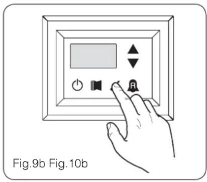
To access the INSTALLER_2 menu, follow the same procedure described for the INSTALLER menu; the only difference is the value of the password, which is 84.
WARNING The following parameters must only be modified by qualified personnel authorised to install the unit.

PASSWORD = 084
text_image
Fig.9b Fig.10b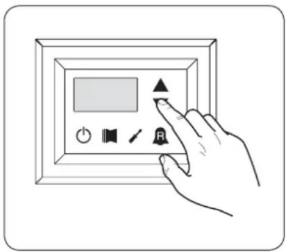
text_image
Hand interacting with a digital display panel showing icons for audio, speaker, and control buttonsSetting operational parameters (installer level)
| Factory settings | |||
| Index - String | MIN value | MAX value | Parameter function |
| 0,1,23 | 0 999 | factory settings | |
| Setting maximum DCP Volt | |||
| Index - String | MIN value | MAX value | Parameter function |
| 4 | 2.0V 9.9V | This parameter allows you to set the maximum speed of the fans in the CL units, the greater the value of this parameter, the higher the pressure available at fan; for an accurate setting of this parameter, please consult the table "Setting maximum DCP Volt "the manual installation of the units CL | |
Managing the electric heater
The units with moducontrol offer the possibility to manage an electric heater; this heater can be managed in different ways:
• supplementary (the simultaneous use of the heat pump and the electric heater);
- anti-freeze, or replacement (the heat pump compressor is switched off and the electric heater alone is activated); The operational specifications of both modes are shown in the diagrams below.
The choice of supplementary or replacement mode depends on the external air temperature, and in case this falls below the threshold indicated in the relative diagram.
WARNING: all parameters referred to in the chart alongside are contained in the electric heater menu, shown on the next pages.
Selection logic for electric heater management mode
Fig.11

text_image
Electric heater REPLACEMENT mode Electric heater SUPPLEMENTARY mode Electric heater always switched off Parameter tA2 (Index 5) Parameter tA1 (Index 4) External air temperatureSupplementary electric heater logic:
Fig.12
flowchart
graph TD
    A["Compressor ON"] --> B["Electric heater ON"]
    B --> C["HEATING SETPOINTS"]
    D["Parameter Bri (Index 3)"] --> E["External air of system water"]
    F["Parameter Sni (Index 2)"] --> E
    G["OFF"] --> H["Ground"]
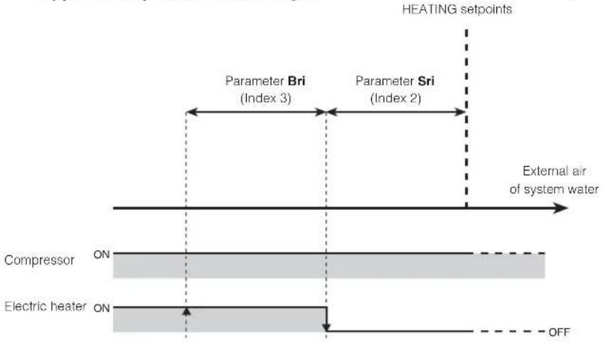
Replacement electric heater logic:
Fig.13
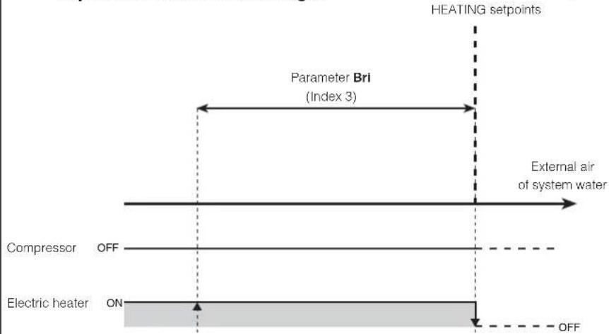
text_image
HEATING setpoints Parameter Bri (Index 3) External air of system water Compressor OFF Electric heater ON OFFELECTRIC HEATER menu
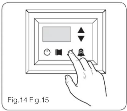
To access the ELECTRIC HEATER menu, press the key in (Fig.14). Once the key has been pressed, you must insert the password to access the various menus; to access the user menu, the password is 001. To modify the value of the passwords, use the arrow keys. When you have inserted the correct password, press the key in (Fig.14). The monitor will show the index of the ELECTRIC HEATER parameter and a 3-character string that identifies it; the string will be displayed for one second, after which it is replaced by the value of the parameter itself. To move on to the next parameter, use the arrow keys (Fig.15). To modify a
parameter, just select it, press the key in (Fig.14), modify the assigned value using the arrow keys in (Fig.15), and confirm the modification by pressing the key in (Fig.14) again.
WARNING The following parameters must only be modified by qualified personnel authorised to install the unit.

PASSWORD = 001
text_image
Fig.14 Fig.15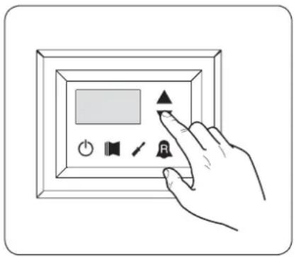
text_image
Hand interacting with a digital display panel showing icons for audio, speaker, and control buttonsSetting operational parameters (electric heater level)
| Setting anti-freeze electric heater setpoints | |||
| Index - String | MIN value | MAX value | Parameter function |
| 0 5rA | -20°C | 50°C | The units offer the possibility to set a threshold for the activation of the anti-freeze electric heater; if the temperature read by one of the two water sensors (input or output, depending on the type of check enabled) reaches the value set in this parameter, the anti-freeze electric heater is activated. |
| Setting anti-freeze electric heater band | |||
| Index - String | MIN value | MAX value | Parameter function |
| 1 brA | 0.3°C 1 | 0°C | The units offer the possibility to set a threshold for the activation of the anti-freeze electric heater; if the temperature read by one of the two water sensors (input or output, depending on the type of check enabled) reaches the value set in this parameter, the anti-freeze electric heater is activated. |
| Setting supplementary electric heater setpoint | |||
| Index - String | MIN value | MAX value | Parameter function |
| 2 Sr1 | 0°C 65°C | This parameter indicates the deviation from the heating setpoint, for switching off the electric heater (if active) in supplementary mode; as shown in Fig.12 on the previous page (Parameter Sri). | |
| Setting electric heater band in supplementary/replacement mode | |||
| Index - String | MIN value | MAX value | Parameter function |
| 3 bri | 0°C 20°C | In supplementary mode, the temperature of the water in the system is checked before the unit is switched on. If the temperature is less than/equal to the value calculated for the switch-on band, the electric heater will be switched on and will operate as per the diagram on the previous page Fig.12. The value of the switch-on band is calculated as follows: switch-on band = (Heating setpoint) - (Parameter Sri) - (Parameter Bri); see Fig.12 on previous page; In replacement mode, this parameter represents the band of deviation from the heating setpoint, within which the heater will be activated or deactivated, as shown on the previous page Fig.13. | |
| Setting outside air temperature threshold for supplementary mode | |||
| Index - String | MIN value | MAX value | Parameter function |
| -40°C | 50°C | This parameter indicates the outside air temperature threshold, beneath which the heater is activated in supplementary mode; as shown on the previous page, in Fig.11 Parameter tA1. | |
| Setting outside air temperature threshold for replacement mode | |||
| Index - String | MIN value | MAX value | Parameter function |
| 5 tA2 | -40°C | 50°C | This parameter indicates the outside air temperature threshold, beneath which the heater is activated in replacement mode; as shown on the previous page, in [Fig.A] Parameter tA2. |
| Setting the band for air temperature | |||
| Index - String | MIN value | MAX value | Parameter function |
| 0°C 20°C | This parameter indicates the band applied to the air temperature setpoints (tA1-tA2). | ||

Parameters only visible in model set for hot water production

Parameters only visible in models set for hot domestic water production

Parameters only visible in the models with DCP installed

Parameters only visible in bicompressor models

Parameters only visible in the models with inverter compressor
Table of DIP-SWITCH configuration
Apart from the parameters that can be inserted from the panel, the units are fitted with a series of dip-switches for managing some options and functions of the machine.
Remember that some of the options that can be managed from the panel are bound to a specific setting of some dip-switches.
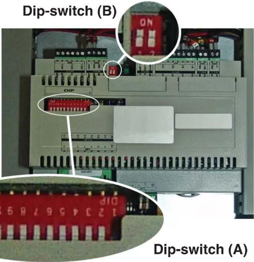
text_image
Dip-switch (B) DIP 123456789 Dip-switch (A)| Heat recovery unit | DIP-SWITCH (A) DIP-SWITCH (B) | |||||||||||||
| 1 | 2 | 3 | 4 | 5 | 6 | 7 | 8 | 9 | 1 | 0 | 1 | 1 | 1 | |
| ANL OFF | OFF OFF | OFF ON | OFF OFF | OFF OFF | OFF OFF | --- | --- OFF | OFF | ||||||
| ANL H ON | OFF OFF | OFF OFF | OFF OFF | OFF OFF | OFF OFF | --- | --- OFF | OFF | ||||||
| ANL C ON | OFF OFF | OFF OFF | OFF OFF | OFF OFF | OFF ON | --- | --- | OFF OFF | ||||||
| ANL A/Q ON | ON OFF | OFF ON | ON | ON | OFF OFF | OFF OFF | --- | --- OFF OFF | ||||||
| ANL HA/ HQ | ON OFF | OFF ON | ON OFF | ON OFF | OFF OFF | OFF --- | --- | OFF OFF | ||||||
| ANL Z/Y ON | ON OFF | ON OFF | OFF OFF | OFF OFF | OFF OFF | --- | --- OFF | OFF | ||||||
| ANLI H | ON | OFF | OFF | OFF | OFF | OFF | OFF | OFF | ON | OFF | --- | --- | ON | OFF |
| ANR H ON | OFF OFF | OFF OFF | OFF OFF | OFF OFF | OFF OFF | --- | --- OFF | OFF | ||||||
| ANR HA/HK | ON OFF | OFF ON | ON OFF | ON OFF | ON OFF | OFF --- | --- | OFF OFF | ||||||
| ANR HP | ON OFF | OFF OFF | OFF OFF | OFF ON | OFF OFF | OFF --- | --- | OFF OFF | ||||||
| ANF H ON | ON | OFF OFF | ON OFF | OFF ON | OFF OFF | --- | --- OFF | OFF | ||||||
| ANF HA/ HK/HJ | ON | ON | OFF | ON | ON | ON | OFF | ON | OFF | OFF | --- | --- | OFF | OFF |
| ANF HP | ON | ON | OFF | OFF | ON | OFF | ON | ON | OFF | OFF | --- | --- | OFF | OFF |
| ANK | ON | ON | OFF OFF | ON OFF | OFF OFF | OFF OFF | --- | --- OFF | OFF | |||||
| ANK Z/Y | ON | ON | ON | OFF | OFF | OFF | OFF | OFF | OFF | OFF | --- | --- | OFF | OFF |
| ANK A | ON | ON | OFF | ON | ON | ON | OFF | OFF | OFF | OFF | --- | --- | OFF | OFF |
| SRP | ON | ON | OFF | ON | ON | OFF | OFF | ON | OFF | OFF | --- | --- | OFF | OFF |
| Dip-switch Status Function | |||
| A | 1 | ON | Machine set as heat pump |
| OFF | Machine set for cooling only | ||
| 2 | ON | Defrosting only by cycle reversal | |
| OFF | Defrosting by hot gas injection | ||
| 3 | ON | Glycol water: anti-freeze setting can be modified | |
| OFF | Anti-freeze setting (parameter B) blocked | ||
| 4 | ON | Output control deactivated | |
| OFF | Output control activated | ||
| 5 | ON | Safety capacity controls deactivated | |
| OFF | Safety capacity controls activated | ||
| 6 | ON | Algorithm for check of low water content deactivated | |
| OFF | Algorithm for check of low water content activated | ||
| 7 | ON | Condensation pressure control device present (accessory DCP) | |
| OFF | Condensation pressure control device absent (accessory DCP) | ||
| 8 | ON | Configuration of the card for ANR unit (R407C) | |
| OFF | Configuration of the card for ANL unit (R410A) | ||
| 9 | ON | Configuration of the card for inverter unit | |
| OFF | Configuration of the card for ON/OFF chiller unit | ||
| 10 | ON | Configuration of the card for condenser unit | |
| OFF | Configuration of the card for chiller unit | ||
| 11 | ON | Not used | |
| OFF | Not used | ||
| 12 | ON | Not used | |
| OFF | Not used | ||
| Dip-switch | Dip combinations | Function | |
| DIP 1 DIP 2 | |||
| B | OFF OFF | Factory settings | |
| ON OFF | Factory settings | ||
| ON ON | Factory settings | ||
| OFF ON | Factory settings | ||
Alarms summary table
The units envision two types of malfunctioning signals:
- Pre-alarm
- Alarm
The first type is indicated by the flashing of the red LED on the display, successive pressing of the bell key allows to display the list of alarms (with index and cause indicated in the table below). A pre-alarm remains such for 60 seconds: if after this time the condition that caused the pre-alarm has not disappeared, the same becomes an alarm. The alarms are displayed in the same way as the pre-alarms,
except for the switch-on of the fixed red LED. Before rearming the unit, it is recommended to contact the after-sales service. To rearm the unit, switch it off and back on again using the stand-by key.
ATTENTION:
The pre-alarms can become alarms when:
- A time has passed longer than or equal to 60 seconds, in the pre-alarm condition.
- The maximum number of pre-alarms in one hour (five) has been exceeded. In this case, every successive pre-alarm will be displayed directly as an alarm, and as such, will stop the machine until the reason for the same is solved.
| Code Alarm | Code Pre-alarm | Causes Notes | |
| 1 101 | Compressor magnet circuit breaker | This signal intervenes if the contact relative to the magnet circuit breaker switch protecting the MTC compressor opens (Table 2, contact ID1, clamps M7.1 - M7.2, normally closed) | |
| Fan magnet circuit breaker | |||
| Pump magnet circuit breaker | |||
| 2 102 | Fan magnet circuit breaker | This signal intervenes if the contact relative to the magnet circuit breaker switch protecting the MTV fans opens (Table 2, contact ID6, clamps M7S.3 - M7S.4, normally closed) This code is displayed only if the board is used as a board spare part with SW up to version 3.6. | |
| 3 103 | High pressure switch | This signal DOES NOT give the state of the high pressure switch itself but of the compressor switch. The high pressure switch operates directly on the compressor switches. If the board commands compressor switch-on and the switch does not become active after 3 seconds, this signal occurs. This alarm can also be caused by an operating defect of the return relay from the compressor switch to the board (indicated as RAP in the wiring diagrams). This signal occurs if the compressor switch deactivates during operation. AP (Table 2, contact ID4, clamps M7.7 - M7.8, normally closed) | |
| 4 104 | Flow switch | This signal occurs with the opening of the contact relative to the differential flow switch or pressure switch; this alarm is not relative for the first 40" from pump start-up. The machine blocks in alarm mode when the maximum number of flow switch interventions allowed (expressed by the set_factory parameter (y): default 5) is exceeded. If the frost protection in standby mode is activated (and therefore also the pump), the state of the flow switch is also controlled. FL/PD (Table 2, contact ID2, clamps M7.3 - M7.4, normally closed) | |
| Water differential pressure switch | |||
| 5 105 | Low pressure switch | This signal intervenes when the contact relative to the low pressure switch opens (compressor intake). BP (Table 2, contact ID5, clamps M7S.1 - M7S.2) | |
| 6 106 | No water inlet probe This signal occurs when the water inlet probe is disconnected | ||
| 7 107 | No water outlet probe This signal occurs when the water outlet probe is disconnected | ||
| 8 108 | Water freezing | This signal occurs when the anti-freeze threshold is reached (set_installer (6) default: 3°C) from the output water temperature. The pre-alarm state is exited with outlet water temperature temperature exceeding the set_installer (6) + set_factory (J) (default 3+1=4°C). The anti-freeze alarm is suspended (in heating mode) for a period of time equal to 3' (set_factory parameter (H)) from compressor switch on. | |
| 9 109 | No pressing line probe | This signal occurs when the pressing line gas probe is absent | |
| 10 | 110 | High pressing line gas temperature | This signal occurs when the temperature of the pressing line gas (SGP probe) exceeds the threshold envisioned by the parameter (set_factory (6), default 135°C). The pre-alarm state is exited with set_factory (7) temperature (default 135 - 10 = 125°C) |
| 11 | 111 | Flow pressure transducer no compressor | This signal occurs when the compressor flow transducer is absent and the machine is set as heat pump or the presence of the DCP is set |
| 12 112 | High pressure | This signal occurs when the transducer detects a flow pressure over the set-factory parameter threshold (8) (default: 40 bar). The pre-alarm state is exited with set_factory (8) - set_factory (b) pressure (default 40 - 2 = 38 bar) | |
| 13 113 | No defrosting probe | This signal occurs when the defrosting probe is absent and the machine is set as heat pump | |
| 14 114 | Intake pressure transducer no compressor | This signal occurs when the compressor intake transducer is absent and the machine is set as heat pump | |
| 15 115 | Low pressure | This signal occurs when the compressor flow transducer indicates an intake pressure below the threshold set by the set_factory (9) parameter in cooling mode (default 4 bar), set_factory(A) ion heating mode (default 2 bar). The pre-alarm state is exited when the intake pressure exceeds the intervention set_factory(b) threshold default equal to 2 bar. The low pressure alarm is suspended in heating mode for a period of time equal to 3' (set_factory parameter (H parameter) from compressor switch on. It is permanently suspended during cycle reverse | |
| 16 - Low | performance | Every time the machine is powered, the control checks compressor behaviour once via the yield control procedure (see 8.1); this control is disabled from dip switch | |
| 17 117 | Pump magnet | circuit breaker | This signal intervenes if the magnet circuit breaker switch protecting the pump is opened. MTP (table 2, contact ID3, clamps M7.5 - M7.6, normally closed). This code is displayed only if the board is used as a board spare part with SW up to version 3.6. |
| 18 118 | High pressure | partialisation | This signal occurs every time a partialisation takes place due to the threshold mentioned in paragraph 8.5 being reached. The machine blocks in alarm mode when the maximum number of partialisation interventions allowed (expressed by the set_factory (5) parameter: default 5) is exceeded. With inverter machine mode, it also indicates a partialisation due to high compression ratio. |
| 19 119 | Low pressure | partialisation | This signal occurs every time a low pressure partialisation takes place, par. 8.5. The machine blocks in alarm mode when the maximum number of partialisations allowed (expressed by the set_factory (5) parameter: default 5) is exceeded. |
| 20 120 | Pressing line temperature partialisation | This signal occurs every time a pressing line temperature partialisation takes place (par. 8.5), the machine blocks in alarm mode when the maximum number of partialisation interventions (expressed by the set_factory (5) parameter: default 5) permitted is exceeded. | |
| 21 121 | Bemf error | Error in detection of the back emf. This error is returned by the inverter control board and is linked to compressor peak problems (longertek 4 code or longertek 20 code) | |
| 22 122 | Internal communication error | The inverter control board has internal communication problems (longertek 5 code) | |
| 23 123 | Over-current | Excess current absorption by compressor (longertek 6 code) | |
| 24 | 124 | No load | The compressor does not absorb enough current, it may turn in idle mode (longertek 7 code) |
| 25 | 125 | Incorrect voltage | The inverter control board indicates incorrect bus voltage (longertek 8 code) |
| 26 | 126 | Error on start-up | The inverter control board indicates incorrect start-up of the PMSM motor (longertek code 9) |
| 27 | 127 | IPM protection error | Error on the IGBT (longertek 12 code) |
| 28 | 128 | EEPROM error | Eeprom error on the inverter control board (longertek 13 code) |
| 29 | 129 | Compressor stall Code longertek 16 | |
| 30 | 130 | No communication | The inverter control board does not respond. It may not be powered or the serial cable could be disconnected or the A and B signals reversed |
| 31 | 131 | PFC Module | PFC inverter module error (longertek 23 code) |
| 32 | 132 | Cooling fin overheating | (code APY 1) |
| 33 | 133 | Over current in acceleration mode | Hardware error (cod. APY 2) |
| 34 | 134 | Over-current at constant speed | Hardware error (cod. APY 3) |
| 35 | 135 | Over current in deceleration mode | Hardware error (cod. APY 4) |
| 36 | 136 | Under-voltage on the DC Bus | (code APY 5) |
| 37 137 | DC Bus over-voltage (code APY 6) | ||
| 40 140 | PFC Converter Fault Error in the PFC module | Software error (code APY 9) | |
| 41 141 | Over current in acceleration mode Software error | (code APY 10) | |
| 42 142 | Overload (code APY 11) | ||
| 43 143 | Over-current at constant speed Software error (code APY 12) | ||
| 44 144 | Over current in deceleration mode Software error | (code APY 13) | |
| 45 145 | Compressor not connected correctly | (code APY 14) | |
| 46 146 | No communication (code APY 15) | ||
| 47 147 | Cooling fin temperature sensor error | (code APY 16) | |
| 51 151 | Anomalous condition | Protection frequency against over-current and overheating reduced. (code APY 20) | |
| 54 -- | Cycle reverse valve faulty | The cycle reverse valve could be faulty or broken. (see 8.4) | |
| 55 155 | Water inlet high temperature | The water inlet temperature has exceeded the set_installer (H) parameter value. Probable boiler presence on same plant. At the third intervention of the pre-alarm, the machine goes into alarm mode and blocks | |
| -- | 156 | Cycle reverse due to high temperature of the pressing line gas | This pre-alarm indicates the intervention of defrosting due to cycle reverse without having respected the times between cycle reverses. Cycle reverse has been triggered by the pressing line gas high temperature partialisation threshold being exceeded, set_factory (6)-set_factory (4) = default 130°. This pre-alarm does not cause compressor stop and does not have a limited number of interventions |
| 57 157 | Reading error of the DHW control board remote probe. | This pre-alarm indicates a remote probe fault or a communication problem with the DHW control board. The alarm is only active if the parameter (0)=2 or the parameter (8)=4 in the menu with password = 30 | |
| 58 158 | Outdoor air temperature probe reading error | This pre-alarm indicates an outdoor air temperature probe fault when the DCP is present or the machine is in heat pump mode. | |
| 59 159 | Inlet water probe no condenser (ONLY WRL) | This pre-alarm indicates a condenser inlet water temperature probe fault | |
| 60 160 | Output water probe no condenser (ONLY WRL) | This pre-alarm indicates a condenser outlet water temperature probe fault | |
| 61 161 | Over-current Carel Inverter | ||
| 62 162 | Compressor motor overload Carel Inverter | ||
| 63 163 | Over-voltage Carel Inverter | ||
| 64 164 | Under-voltage Carel Inverter | ||
| 65 165 | Drive overheating Carel Inverter | ||
| 66 166 | Drive underheating Carel Inverter | ||
| 67 167 | Hardware over-current Carel Inverter | ||
| 68 168 | Compressor overheating Carel Inverter | ||
| 69 169 | Reserved Carel Inverter | ||
| 70 170 | CPU error Carel Inverter | ||
| 71 171 | Default parameters Carel Inverter | ||
| 72 172 | DC bus ripple Carel Inverter | ||
| 73 173 | No communication between invert-er and uPC | Carel Inverter | |
| 74 174 | Drive temperature sensor fault Carel Inverter | ||
| 75 175 | Self-configuration failed Carel Inverter | ||
| 76 | 176 | Inverter drive disabled | Carel Inverter |
| 77 177 | Motor phases error Carel Inverter | ||
| 78 178 | Cooling fan Inverter faulty | Carel Inverter | |
| 79 179 | Speed fault Carel Inverter | ||
| 80 180 | PFC fault | Alarm that occurs with PFC enabled while the bus DC is very low | |
| 81 181 | PFC overload trip | This alarm will no longer be present in the new firmware versions. | |
| 82 182 | Input voltage error | When the power supply drops below 170 V with engine running | |
| 83 183 | Generic inverter error Carel Inverter, carel modbus | address 213 | |
| 84 184 | Probe B1 fault (uPC) Control wiring | ||
| 85 185 | Probe B2 fault (uPC) Control wiring | ||
| 86 186 | Probe B3 fault (uPC) Control wiring | ||
| 87 187 | Probe B4 fault (uPC) Control wiring | ||
| 88 188 | Probe B5 fault (uPC) Control wiring | ||
| 89 189 | Probe B6 fault (uPC) Control wiring | ||
| 90 190 | Probe B7 fault (uPC) Control wiring | ||
| 91 191 | High pressure alarm (uPC) Control wiring | ||
| 92 192 | Low pressure alarm (uPC) Control wiring | ||
| 93 193 | Gas high temperature alarm pressing line (uPC) | Control wiring | |
| 94 194 | Pressure differential lower than that specified (uPC) | Control wiring | |
| 95 195 | Compressor start-up failed (uPC) | Control wiring | |
| 96 196 | Time exceeding operational limits alarm (uPC) | Control wiring | |
| 97 197 | Super Heat low alarm (uPC) Control wiring | ||
| 98 198 | MOP alarm (uPC) Control wiring | ||
| 99 199 | Low intake temperature alarm (uPC) | Control wiring | |
| 200 | 300 | EVD EVO alarm: Evotunes alarm (uPC) | Control wiring |
| 201 | 301 | EVD EVO regulation alarm (uPC) | Control wiring |
| 202 | 302 | EVD EVO system alarms probe errors alarm (uPC) | Control wiring |
| 203 | 303 | Reserved. (uPC) | Control wiring |
| 204 | 304 | No communication between invert-er and uPC. (uPC error) | Control wiring |
| 205 | 305 | Inverter not compatible with the compressor selected (uPC) | Control wiring |
| 206 | 306 | Delta P greater than the permit at start up (uPC) | Control wiring |
| 207 | 307 | Low pressure limit | Discharged unit |
ATTENZIONE:
natural_image
Weather warning symbol with a red X sign over a box, no text or numbers presentnatural_image
Symbolic representation of a person standing on a yellow box with a red X mark, no text or labels present.natural_image
Illustration of two gloves, one white and one black, overlapping without any text or symbols.| Unité | ANL | 0 | 7 | 5 | 4 | 5 | 5 | 0 | 1 | 2 | 1 | 8 | 7 | 3 | 0 | 4 | ||
| ANLI | 0 | 7 | 5 | 4 | 5 | 5 | 0 | 1 | 2 | 1 | 8 | 7 | 3 | 0 | 4 | |||
| ANR | 0 | 7 | 5 | 4 | 5 | 5 | 0 | 1 | 2 | 1 | 8 | 7 | 3 | 0 | 4 | |||
| ANF | 0 | 7 | 5 | 4 | 5 | 5 | 0 | 1 | 2 | 1 | 8 | 7 | 3 | 0 | 4 | |||
| ANK | 0 | 7 | 5 | 4 | 5 | 5 | 0 | 1 | 2 | 1 | 8 | 7 | 3 | 0 | 4 | |||
| SRPV1 | 1 | --- | --- | 65 | 5 | 0 | 12 | 18 | 7 | 30 | 45 | 0 | 35 | 18 | 50 | 10 | ||
| SRA | 1 | --- | --- | 65 | 5 | 0 | 12 | 18 | 7 | 30 | 45 | 0 | 35 | 18 | 50 | 10 | ||
| WRL | --- 7 | 5 | --- --- 0 | 12 | 18 7 30 | --- --- | --- --- | --- --- | ||||||||||
| √ | Configuration DISPONIBLE |
| × | Configuration NON DISPONIBLE |
text_image
A B SET 8-888 C D E Fig.1 Ftext_image
Diagram showing a hand interacting with a digital display panel, including icons for power, speaker, and button.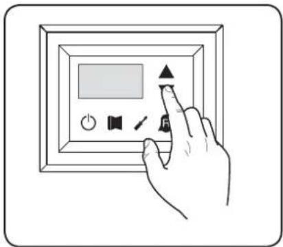
natural_image
Hand interacting with a digital display panel and control buttons (no text or symbols visible)Signification de la lecture
text_image
Fig.7 Fig.8
text_image
Hand interacting with a digital display panel showing icons for audio, sound, speaker, and signal controltext_image
Hand interacting with a digital display panel showing icons for power, speaker, audio, and buttontext_image
Hand interacting with a digital display panel showing icons for power, sound, speaker, and buttontext_image
Fig.9a Fig.10a
text_image
Hand interacting with a digital display panel showing icons for power, speaker, and function buttonstext_image
Fig.9b Fig.10b
text_image
Hand interacting with a digital display panel showing icons for power, speaker, audio, and control buttonstext_image
Hand interacting with a digital display panel showing icons for audio, speaker, sounder, and timer controlnatural_image
Weather warning symbol with a red X sign over a box, cloud above rain and falling rain (no text or numbers present)text_image
Warning sign with a black human figure and red X symbol on a yellow box, indicating no change or failure.natural_image
Illustration of two gloves, one white and one black, overlapping without any text or symbols.text_image
A B SET 8 - 888 F C D E Fig.1text_image
5 6 7 8 9 1 SET 8 - 88.8 2 3 4 Fig.2text_image
Fig.4 Fig.5 Fig.6
text_image
Hand holding a digital display control panel with icons for power, speaker, signal, and alarm
text_image
Hand interacting with a digital display panel showing icons for power, settings, and function buttonstext_image
Fig.7 Fig.8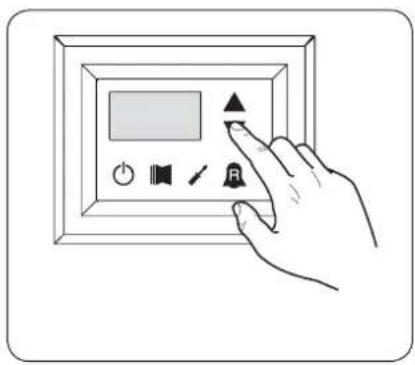
text_image
Hand interacting with a digital display panel showing icons for audio, speaker, and buttontext_image
Hand interacting with a digital display panel showing icons for buttons, speaker, and timertext_image
Hand interacting with a digital display panel showing icons for power, sound, settings, and buttonstext_image
Fig.9a Fig.10a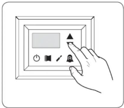
text_image
Hand interacting with a digital display panel showing icons for power, speaker, audio, and screen controltext_image
Fig.9b Fig.10b
text_image
Hand interacting with a digital display panel showing icons for power, speaker, and audio controltext_image
Hand interacting with a digital display panel showing icons for power, speaker, and buttonnatural_image
Weather warning symbol with a red X sign over a box and cloud above rain (no text or numbers present)text_image
Warning sign with a human figure and red X symbol on a yellow box, indicating no change or failure.Manipular con cuidado

natural_image
Illustration of two gloves, one white and one black, overlapping without any text or symbols.- Menú SET (tecla (D) Fig.1)
text_image
A B SET 8 - 888 C D E F fig. 1text_image
Fig.4 Fig.5 Fig.6
text_image
Hand holding a digital display panel with control buttons including power, speaker, timer, and alarm symbol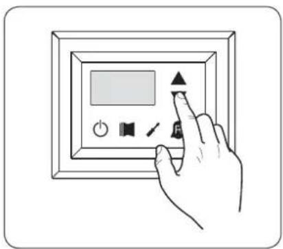
text_image
Hand interacting with a digital display panel showing icons for power, speaker, and function buttonstext_image
Fig.7 Fig.8
text_image
Hand interacting with a digital display panel showing icons for audio, sound, speaker, and signal controltext_image
Hand interacting with a digital display panel and control buttons, including a play button and speaker icontext_image
Hand interacting with a digital display panel showing icons for power, sound, speaker, and buttonnatural_image
Hand interacting with a digital display panel showing icons for power, speaker, and button (no text or symbols)text_image
Fig.9b Fig.10b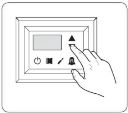
text_image
Hand interacting with a digital display panel showing icons for power, speaker, audio, and control buttonstext_image
Hand interacting with a digital display panel showing icons for power, speaker, sound, and signal controlTechnical data shown in this booklet are not binding.