FCW 312V - Air Conditioning Aermec - Free user manual and instructions
Find the device manual for free FCW 312V Aermec in PDF.

| Brand | Aermec |
| Model | FCW 312V |
| Product type | Fan coil unit |
| Power supply | 230 V ±10%, 50 Hz, single-phase |
| Operating modes | Auto, Heating, Cooling, Ventilation, Dehumidification |
| Fan speeds | 3 speeds (LOW, MED, HIGH) + auto (AUTO) |
| Set temperature range | 16 °C to 30 °C |
| Maximum inlet water temperature | 70 °C |
| Maximum working pressure | 13 bar |
| Minimum water flow (size 31) | 100 L/h |
| Maximum water flow (size 31) | 750 L/h |
| Valve type | Built-in 2-way (2V model) |
| Control | Microprocessor electronic board; requires TLW2 remote control or PFW2 wired panel (mandatory accessories) |
| Display | Screen on front panel (temperature, speed, mode, timer, errors) |
| Horizontal deflector | Motorized, adjustable via remote control or panel |
| Vertical vanes | Manually adjustable |
| Certifications | CE, Eurovent, LVD 2006/95/EC, EMC 2004/108/EC |
| Air filter | Washable; clean every 15 days (vacuum or water + neutral detergent) |
| External cleaning | Damp cloth at max 40 °C with neutral soap; do not spray water |
| Programming | On/Off timer (1-24 h depending on control) and Sleep function (night comfort) |
| Safety | Emergency stop via auxiliary switch; short circuit protection |
| VMF system compatibility | Centralized multi-zone management up to 384 fan coil units |
Frequently Asked Questions - FCW 312V Aermec
User questions about FCW 312V Aermec
0 question about this device. Answer the ones you know or ask your own.
Ask a new question about this device
Download the instructions for your Air Conditioning in PDF format for free! Find your manual FCW 312V - Aermec and take your electronic device back in hand. On this page are published all the documents necessary for the use of your device. FCW 312V by Aermec.
USER MANUAL FCW 312V Aermec
vENTILCONvETTORE pER INSTALLAZIONA A pARETE WALL-MOUNTED fAN COIL UNIT
vENTILO-CONvECTEUR pOUR INSTALLATION MURALE
Do NOT wet. Protect from rain
CRAINT l'humidité
Vor Nasse schützen
NO mojar
NON calpestare
Do NOT stand on
Fragile, handle with care
CDECLARATION OF CONFORMITY
We, the undersigned declare, under our own exclusive responsibility, that the product:
FAN COIL
FCW series
to which this declaration refers, complies with the following harmonised standards:
-
EN 60335-2-40 - EN 55014-1
-
EN 55014-2
- EN 61000-6-1
- EN 61000-6-2
thus meeting the essential requisites of the following directives:
- Low Voltage Directive: LVD 2006/95/EC
- Electromagnetic Compatibility Directive: EMC 2004/108/EC
- Machinery Directive: 2006/42/EC
FCW WITH ACCESSORIES
It is not allowed to operate the unit equipped with accessories not supplied by Aermcc.
VMF (schema Variable Multi Flow)
1) ACCENDERE CON I TASTIO on/off
1) ACCENDERE CON I TASTIO on/off
Thank you for choosing an AERMEC product. It is the fruit of many years of experience and special design studies and has been made of the highest grade materials and with cutting edge technology.
The CE marking indicates that the products comply with the essential requirements of the applicable European Community directives. The quality level is being constantly monitored, so AERMEC products are synonymous with Safety, Quality and Reliability.
To find our nearest After Sales Service office, ask for information in the shop where you purchased the unit.
On our website www.aermec.com you can find the necessary technical documentation for all our products, along with the addresses of the sales and assistance networks.
The data may be modified as considered necessary in order to improve the product.
Thank you once again.
AERMEC S.p.A
TABLE OF CONTENTS
| Observations • Safety warnings • On receipt of the unit • Packaging • Disposal 30 | |
| Maintenance • Troubleshooting 31 | |
| Description of the unit 32 | |
| Main components • Description of the components 33 | |
| General information 34 | |
| Important information • Operational limits 35 | |
| Direction of the air flow 36 | |
| Control keys and signals (FCW with microprocessor controller) 37 | |
| TLW2 - Infra-red remote control 38 | |
| PFW2 - Wired control panel 40 | |
| Automatic programme • Heating programme 41 | |
| Cooling programme • Fan programme 42 | |
| Dehumidification programme • Night comfort function 43 | |
| Turn on programmed by the timer • Turn off programmed by the timer | 44 |
| Dimensions • Installation | 45 |
| Wiring diagrams | 110 |
OBSERVATIONS
Keep the manuals in a dry place to prevent deterioration for any future reference needs and at least for 10 years.
Carefully and thoroughly read all the information referred to in this manual. Pay particular attention to the instructions for use accompanied by the words "DANGER" or "WARNING" and the "Safety Symbols": failure to comply with these could result in material damage to the machine/ property and/or personal injury.
For any irregularities not foreseen by this manual, promptly contact your local After Sales Service.
The device must be installed in such a way that maintenance and/or repair operations are possible.
The warranty of the device does not in any case cover costs owing to ladder trucks, lifts or other lifting systems that may be required in order to carry out repairs under warranty.
AERMEC S.p.A. accepts no liability for any damage due to improper use of the unit, or the failure to read the information contained in this manual fully and carefully.
This manual contains the following number of pages: 120
SAFETYWARNINGS
Particular attention must be paid to the following symbols:

WARNING! This symbol indicates operations which, if carried out incorrectly, can cause death or serious personal injury.
WARNING! This symbol indicates operations which, if carried out incorrectly, can cause serious personal injury or material damage.
DANGER!
DANGER! : Voltage
DANGER! : Moving parts
ON RECEIPT OF THE UNIT
On receipt of the unit, it is essential to check that:
-
the packages match the details on the documentation accompanying the goods
-
the boxes are intact and have not been damaged in transit.
If any anomalies are found:
-
immediately notify the haulier of the damage
-
immediately notify the vendor of the damage.
PACKAGING
The air conditioners are shipped in standard packaging which consists of expanded polystyrene foam shells and cardboard.
INFORMATION CONCERNING THE DISPOSAL OF ELECTRIC AND ELECTRONIC EQUIPMENT

Warning: this product contains electric and electronic equipment that cannot be scrapped via the normal waste collection channels.
There are specially identified collection points for these products.
The electric and electronic equipment must be handled separately, and in accordance with the legislation in force in that specific country.
Batteries or rechargeable batteries in the equipment must be recycled separately, in accordance with the regulations in that specific community.
MAINTENANCE
ORDINARY MAINTENANCE
The ordinary maintenance can be carried out by the user and consists of a series of simple operations, which will ensure that the fan coil unit operates at full efficiency. Operations:
- External cleaning to be done with a damp cloth (soaked in water no hotter than 40^ ) and a neutral detergent avoid using any other type of detergent or solvent.
Do not splash water on interior or exterior surfaces of the fan coil unit (it could cause short circuits). - Filter cleaning, every two weeks or weekly if installed in very dusty environments. Clean the filter with a vacuum cleaner and possibly with water and a neutral detergent; avoid using any other type of detergent or solvents.
- Visual inspection of the state of the fan coil unit for every maintenance operation; any fault must be communicated to the After-Sales Service.
SPECIAL MAINTENANCE
Special maintenance can only be performed by Aertec After-Sales Services or by people with the technical and professional expertise qualifying them to undertake installation, modification, expansion and maintenance of the systems and are able to check them in terms of safety and functionality. In particular with regard to electrical connections the following tests are required relative to:
-
Measurement of the electrical system insulation resistance.
-
Continuity test of the protective wiring.
The special maintenance consists of a series of complex operations that involve dismantling of the fan coil unit or its components to ensure the maximum fan coil unit efficiency is restored.
Operations:
- Internal cleaning, annually or after long periods of inactivity; in environments where a high degree of air cleaning is required, cleaning can be more frequent. This consists of: cleaning of the coil, fan blades, drain pan and all the parts in contact with the treated air.
- Repairs and setting up; when faults arise look at the "TROUBLESHOOTING" chapter in this manual before calling the After-Sales Service.
TROUBLESHOOTING
| PROBLEM | PROBABLE CAUSE | SOLUTION |
| Insufficient air flow at outlet | Incorrect speed setting on control panel | Select the correct speed on the control panel |
| Blocked filter | Clean the filter | |
| Obstructed air flow (inlet and/or outlet) | Remove the obstacle | |
| Unit does not heat | No hot water | Check the boiler |
| Check the heat pump | ||
| Incorrect control panel setting | Set the control panel correctly | |
| T water > 90°C | Reduce the water temperature, then remove and reapply electrical power | |
| Unit does not cool | No cold water | Check the chiller |
| Incorrect control panel setting | Set the control panel correctly | |
| Fan not operating | No electrical power | Check that there is electrical power |
| Water has not reached operating temperature. | Check the boiler or the chiller and/or check the set point | |
| Condensation forming on the external case of the unit | Temperature and humidity limits specified by “MINIMUM AVERAGE WATER TEMPERATURE” have been reached | Raise the water temperature to above the limits specified by “MINIMUM AVERAGE WATER TEMPERATURE” |
For any problems not listed, contact the After-Sales Service immediately.
FCW WALL-MOUNTED FAN COIL UNIT
The Aermec FCW fan coil unit is made with materials of superior quality in strict compliance with safety regulations. The "FCW" is easy to use and will have a long life.
The fan coil unit is a terminal unit for conditioning internal air both in winter and summer.
The FCW fan coil unit for wall mounted installation concentrates high technological and functional characteristics that make it the ideal climate control unit for all environments.
The supply of climate controlled air is immediate and distributed throughout the room; FCW generates heat if included in a heating system with a boiler or heat pump but may also be used in the summer as an air conditioner if the system has a water chiller.
The fan coil unit is designed to ensure maximum compliance with safety regulations.
Several versions of FCW fan coil units are available in order to satisfy all types of installations:
- with internal 2-way-valve,
- with internal 3-way-valve
- without valve.
Each version is available: - With microprocessor controller (requires the addition of the PFW2 wired control panel accessory or the TLW2 remote control accessory.)
- Without microprocessor controller
which then requires a cable connected accessory panel or connection to the accessories of the VFM system (the VMF-E0 and VMF-E1 thermostats cannot be installed internally to the fan coil unit).
In particular, the possibility to be integrated into the VMF system allows the control of a single fan coil unit with accessories, up to the control of the fan coil unit installed in a complex network.
Unit configuration
By choosing the appropriate options it is possible to select the model to suit the specific system requirements:
12345678
III
Code
FCW
Size
21
31
41
Valve
2V (2-way valve fitted inside)
3V (3-way valve fitted inside)
VL (without valve)
Microprocessor Controller
(Blank) with controller
N without controller
Versions
- 2V version with 2-way valve fitted inside.
Microprocessor controller.
Wired control panel PFW2 or remote control TLW2.
- 2VN version with 2-way valve fitted inside.
Standard control or VMF System.
- 3V version with 3-way valve fitted inside.
Microprocessor controller.
Wired control panel PFW2 or remote control TLW2.
- 3VN version with 3-way valve fitted inside.
Standard control or VMF System.
- VL without valve version.
Microprocessor controller.
Wired control panel PFW2 or remote control TLW2.
- VLN without valve version.
Standard control or VMF System.
MAIN CHARACTERISTICS:
EUROVENT Certification
- The response to the commands is immediate if the room temperature and the temperature of the water in the system so allows
- Tangential three-speed fan assembly
- Very quiet operation
Aesthetic design
Cream colour - Display on panel front
- Horizontally adjustable discharge air blades
Horizontal deflector blades to vertically adjust discharge air. Manually adjustable only for units without microprocessor controller. For units with microprocessor controller adjustable only via PFW2 wired control panel or TLW2 remote control
- Ease of installation with hydraulic and condensate drain connections adjustable in several directions
- Routine maintenance is limited to
periodic cleaning of the air filter
Full compliance with safety regulations.
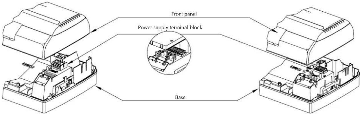
MAIN COMPONENTS
1 Front panel
6 Auxiliary emergency switch
2 Horizontal air discharge blades
7 Electric terminal connections
3 Vertical air discharge blades
8 Front case
4 Air filter
9 Frame
5 Heat exchanger coil
10 Display
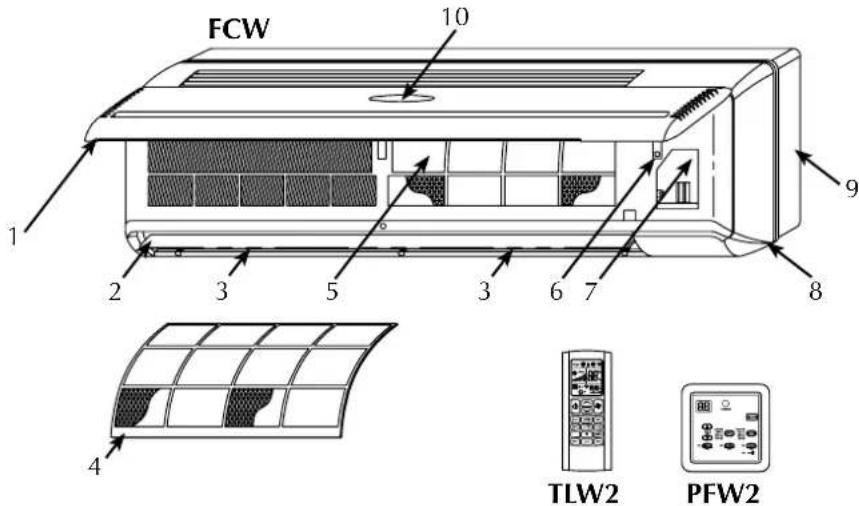
DESCRIPTION OF COMPONENTS
FRONT PANEL
The air intake is via the slots. Lifting the panel gives access to the air filter and the internal parts
RECEIVER
Infra red signal receiver for versions with microprocessor controller
DISPLAY
The display is mounted on the front panel, only for versions with microprocessor controller. It shows the fan speed, operating mode, temperature, error messages, and timer
AIR FILTER
Washable air filter that can easily be removed
HEAT EXCHANGER COIL
Made of copper tubes with turbo lanced aluminium fins
DISCHARGE AIR
The horizontal blades are:
motorised for versions fitted with microprocessor controller.
- manual for versions not fitted with microprocessor controller
The vertical blades are manually adjustable to allow optimal air discharge
AUXILIARY EMERGENCY SWITCH
The auxiliary emergency switch, only for versions with microprocessor controller, allow the fan coil unit to be turned on or off if the wired control panel or remote control are not oper
ating
FAN ASSEMBLY
The fan assembly consists of an extremely compact and quiet tangential type fan.
2-WAY WATER VALVE
The FCW_2V fan coil unit is supplied as standard with a 2-way on/off water valve and electro-thermal actuator controlled by the fan coil controller, based on the water temperature and the temperature of the room
3-WAY WATER VALVE
The FCW_3V fan coil unit is supplied as standard with a 2-way on/off water valve and electro-thermal actuator controlled by the fan coil controller, based on the water temperature and the temperature of the room
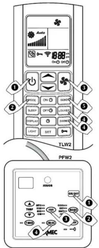
TLW2 REMOTE CONTROL (FCW accessory for versions with microprocessor controller)
Accessory essential for the fan coil unit operation, as an alternative to the PFW2 wired control panel.
The TLW2 remote control is provided loose from the fan coil unit. One remote control can control several fan coil units.
The remote control makes it possible to set all the operating parameters of the unit. These parameters are shown on a liquid crystal display making programming operations easier.
The remote control is supplied with a bracket allowing it to be hung on the wall.
PFW2 WIRED CONTROL PANEL (FCW accessory for versions with microprocessor controller)
Accessory essential for the fan coil unit operation, as alternative to the TLW2 remote control.
The wired control panel must be installed on the wall and connected to the fan coil unit with the cable provided loose.
The panel cable is 4 metres long.
The PFW2 makes it possible to set the main operating parameters of the unit. These parameters are shown on a liquid crystal display making programming operations easier.
A PFW2 wired control panel can control just one fan coil unit.
GENERAL INFORMATION
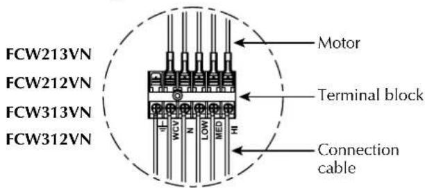
- Versions without microprocessor controller:
With or without water valve.
Versions without microprocessor controller need to be combined with a control panel (accessory) chosen from standard control panels (compatible with the configuration of the fan coil unit) or be combined with a thermostat from the VMF system.
Warning! The VMF (VMF-E0 / VMF-E1) thermostat can not be installed inside the fan coil unit but the installer must provide an adequate housing close to the fan coil unit (such as a recessed electrical box on the wall behind the fan).
VMF (Variable Multi Flow System)
Management and control system of hydronic systems for the air-conditioning, heating and production of domestic hot water.
The VMF system allows complete control of every component of a hydronic system both locally and centrally and, communicating between the various components of the system, manages the performance without ever neglecting the end user's request of comfort, but reaching it as efficiently as possible with energy saving.
If you add the advantages deriving from such an innovative control to the flexibility of a hydronic system, you get a more efficient and effective alternative to the variable refrigerant flow systems (VRF).
The VMF system is extremely flexible, enough to allow various steps of control and management, expandable at different moments:
1) Control of a single fan coil unit.
2) Control of a microzone (one MASTER fan coil unit and a maximum of 5 SLAVE fan coils units).
3) Control of multi independent zones system (one MASTER fan coil
unit and a maximum of 5 SLAVE fa coil units for each zone).
4) Control of a fan coil unit system, plus management of the heat pump (if compatible with the VMF system).
5) Control of a fan coil unit system, heat pump and management of the domestic hot water system (VMF-ACS).
6) Control of a fan coil unit system, heat pump, domestic hot water production and additional circulators (up to a maximum of 12 using three additional VMF-CRP modules).
7) Control of a fan coil unit system, heat pump, domestic hot water production, additional circulators and management of heat recovery units, maximum 3, (with the ability to handle up to 3 VMF-VOC sensors) or a boiler.
- The VMF system can operate and manage, through a VMF-E5N / VMF-E5B panel, a maximum of 64 zones consisting of a MASTER fan coil unit and a maximum of 5 SLAVE fan coil units connected to each MASTER, for a total of 384 fan coil units.
Besides the central control supplied by the VMF-E5N / VMF-E5B panel, the MASTER fan coil units must be provided with a local control interface; this interface can be mounted on the fan coil unit (only for the models where it is possible) or be mounted into a wall panel (VMF-E4 / VMF-E4D).
- Different functions can be controlled through the VMF-E5N / VMF-E5B panel, including:
- Identify the different zones giving a name for each one.
- Check and set the ON-OFF function and the set point temperature of each zone.
- Set and manage the set point temperature of the heat pump.
- Scheduling time clocks.
- Simple installation of the fan coil unit system through the SELF-MONITORING function of the MASTER fan coil units.
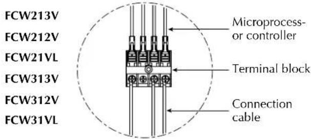
- Versions with microprocessor controller:
With or without water valve.
Versions with microprocessor controller have a display on the front panel showing the main functions of the unit.
The versions with microprocessor controller need to be combined with one of the two available control systems (accessories PFW2 or TLW2) provided as required as a necessary accessory for the unit operation allowing turning on, turning off and all the fan coil unit control and programming operations.
The two control systems cannot be used at the same time on the same fan coil unit.
The control system checks all the functioning parameters and carries out all the operations necessary to enable the required room conditions to be maintained.
The control system also provides some automatic functions to increase comfort and make the most frequently repeated operations easier:
- Minimum temperature sensor; in order to avoid cold air blasts in the winter mode, allowing ventilation only if the water in the system is hot.
- Auto Restart mode, after a power outage the FCW unit starts again automatically with the same settings that it had at the time of stopping (with the exception of the Timer and Sleep settings).
IMPORTANT INFORMATION
WARNING: The fan coil unit is connected to the power supply and a water circuit. Operations performed by persons without the required technical skills can lead to personal injury to the operator or damage to the unit and surrounding objects.
MALFUNCTION
In the case of a malfunction remove power to the unit then reapply it and start the unit again. If the problem occurs again, call your area After-Sales service department promptly.
POWER THE FAN COIL UNIT ONLY WITH 230 VOLT, SINGLE PHASE, 50Hz
Use of other power supplies could cause permanent damage to the fan coil unit.
USE THE (TLW2) REMOTE CONTROL OR THE WIRED CONTROL PANEL (PFW2) TO TURN THE FAN COIL UNIT ON AND OFF
Do not turn the fan coil unit on or off using the auxiliary switch except in an emergency.
DO NOT PULL THE ELECTRICAL CABLE
It is very dangerous to pull, tread on or crush the electrical power cable or fix it with nails or drawing pins.
A damaged power cable can cause short circuits and personal injury.
DO NOT PUT ANYTHING IN THE AIR OUTLETS
Do not put anything at all in the air outlet slots. This could cause injury to people and damage to the fan.
DO NOT USE THE FAN COIL UNIT IMPROPERLY
Do not use the fan coil unit in animal husbandry applications.
VENTILATING THE ROOM
Periodically air the room in which the fan coil unit has been installed; this is particularly important if the room is occupied by many people, or if gas appliances or sources of odours are present.
CORRECTLY CONTROLLING THE TEMPERATURE
The room temperature should be controlled in order to provide maximum comfort to the people in the room, especially if they are elderly, children or ill, avoiding sudden changes in temperature between the outside and inside above 7^ in summer.
Careful choice of the room temperature will lead to energy savings.
CORRECTLY ADJUSTING THE AIR JET
The air coming out of the fan coil unit must not strike people directly; in fact, even if at a temperature that is higher than the room temperature, it could cause a cold sensation and resulting discomfort.
Only adjust the vertical blades by hand.
In the versions with microprocessor controller adjust the horizontal blade with the LOUVRE or SWING key of the remote control or the wired control panel.
In the versions without microprocessor controller adjust the horizontal blades by hand.
DURING OPERATION
Always leave the filter in the fan coil unit during operation otherwise dust in the air will dirty the surfaces of the coil.
WHAT IS NORMAL
During cooling, water vapour may be present in the air discharge.
During heating it might be possible to hear a slight hiss around the fan coil unit. Sometimes the fan coil unit might give off unpleasant smells due to the accumulation of substances from the air of the room (especially if the room is not ventilated regularly. Clean the filter more often).
During operation, there could be noises and creaks inside the device, due to the thermal expansion of the various components (plastic and metallic), but this does not indicate a malfunction and does not cause damage to the unit unless the maximum input water temperature is exceeded.
OPERATIONAL LIMITS
Maximum inlet water temperature. 70°C Maximum operating pressure. 13 bar
The installation site must be chosen in such a way that the maximum and minimum room temperature limits, Ta, are respected: 0^ < T_a < 40^ ; R.H. < 85% .
Connect to a 230V 50Hz power supply and earth connection, and ensure it remains within the limit of ± 10% with respect to the nominal value.
Flow rate limits:
| MODEL | FCW | 21 | 31 | 41 |
| Minimum flow rate | [I/h] | 100 | 100 | 150 |
| Maximum flow rate | [I/h] | 750 | 750 | 1100 |
Minimum average water temperature
To prevent the formation of condensation on the exterior of the unit while the fan coil unit is operating, the average water temperature should not drop beneath the limits shown in Table 1.
MINIMUM AVERAGE WATER TEMPERATURE
in the table below, determined by the ambient conditions. These limits refer to unit operation with fan at minimum speed.
Dry bulb temperature of the air in the room ^ C
| 21 | 23 | 25 | 27 | 29 | 31 | |||
| 15 | 3 | 3 | 3 | 3 | 3 | 3 | ||
| Wet bulb temperature 17 of the air in the room °C | 3 | 3 | 3 | 3 | 3 | 3 | 3 | |
| 19 | 3 | 3 | 3 | 3 | 3 | 3 | ||
| 21 | 6 | 5 | 4 | 3 | 3 | 3 | 3 | 3 |
| 23 | - | 8 | 7 | 6 | 5 | 5 | - | - |
IMPORTANT
Note for FCW series with microprocessor controller:
- The two control types, wired control panel (PFW2) and remote control (TLW2), cannot be used at the same time on the same fan coil unit.
If the fan coil is off, all the previous settings made are kept in the memory except for the TIMER setting and SLEEP mode. - If the fan coil is turned on using the (ON/OFF) key, the TIMER setting and SLEEP mode are cancelled.
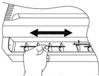
DIRECTION OF THE AIR FLOW
The blades on the air discharge are arranged to direct the air in two directions:
vertical blades, to be adjusted manually
motorised horizontal blades for versions with microprocessor controller, to be adjusted only by means of the TLW2 remote control or the PFW2 wired control panel
- horizontal blades for versions without microprocessor controller to be adjusted manually.
ADJUSTING THE VERTICAL BLADES
- turn the vertical blades as indicated in the diagram
- both in heating or cooling mode it is advisable for the air flow not to hit people directly.
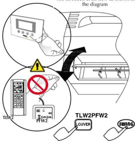
MOTORISED HORIZONTAL BLADES
Never adjust the motorised horizontal blades manually. Any manual operation on the blades may damage the system and cause a malfunction.
When the unit is off the blades close and cover the air flow outlet.
IMPORTANT
Under particular external conditions condensate might occur on the surface of the blades (during cooling and dehumidification) and drip onto the surfaces below.
The direction of air flow as shown in the diagram
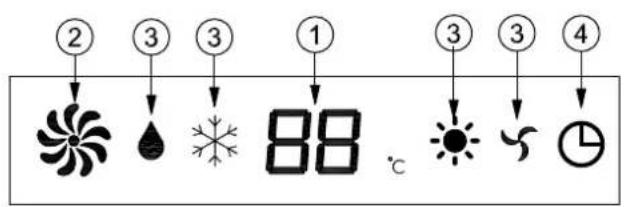
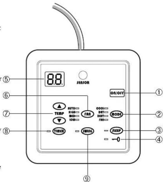
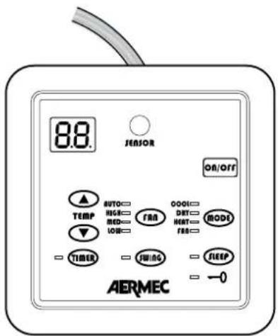
fCw wITH MICROpPROCESSOR CONTROLLER - fRONT pANEL DISpLAy
When the fan coil unit is powered up it emits a beep.
When the fan coil unit is powered but not on, all the LEDs are off.
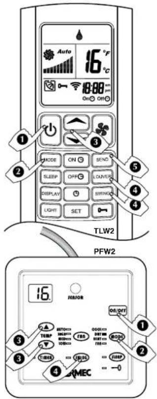
1- TEMperATURE DISpLay / ERROR CODES
- In normal operation shows the room temperature
- If the set point temperature is changed the new value in ^ C will blink for 5 seconds
- Room sensor error: E1 will blink
- Internal sensor error: E2 will blink
- Water sensor error: E3 will blink
- Water temperature sensor error: E4 will blink.
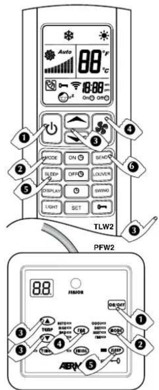
2 -fAN SpEED
3-OpERATING MODE
Dehumidification
*Cooling
Heating
Fan only
4-TIMER
The icon shows the timer is active
fCw wITH MICROPROCESSOR CONTROLLER - AUXILIARY EMERGENCY SwITCH
AUXILIARY EMERGENCY Switch
When the remote control is not available (not functioning or with flat batteries) or the wired control panel is not functioning, the auxiliary emergency switch can be used to activate the fan coil unit.
The switch is not sized for continuous use. Repair the remote control or the wired control panel as soon as possible.
Starting and operating with the auxiliary emergency switch (AUX):
- First press: Cooling with set point 25^ , automatic ventilation, swinging blades
- Second press: Heating with set point 22^ , automatic ventilation, swinging blades
- Third press: Fan coil unit turned off
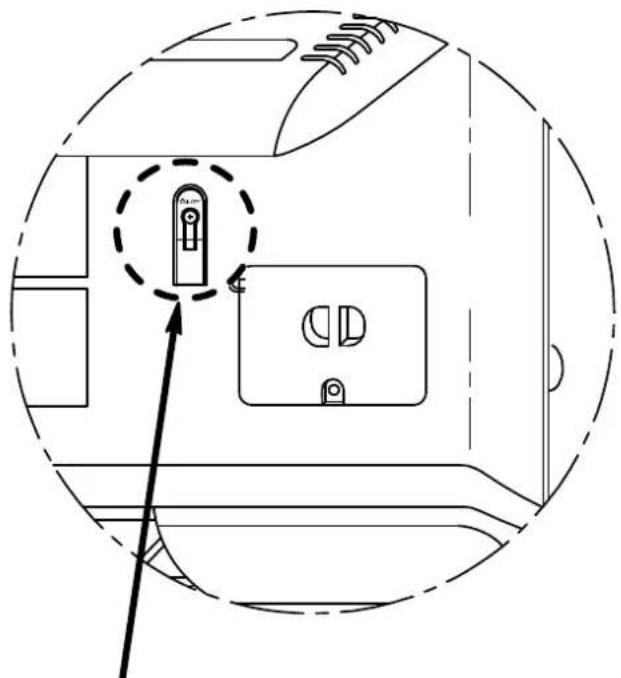
AUX (On/Off)
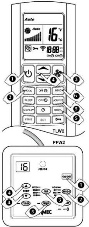
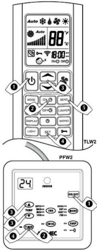
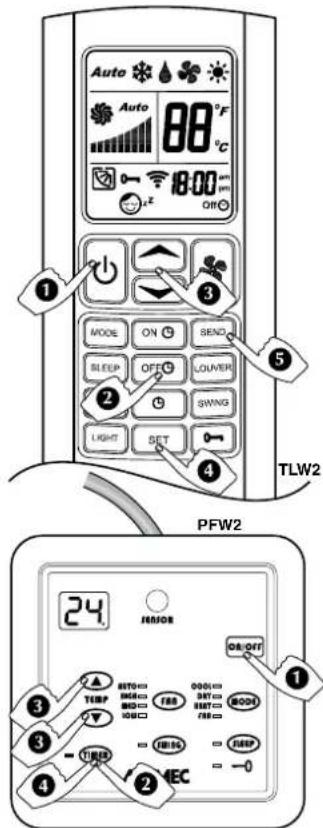
TLW2 - INFRA-RED REMOTE CONTROL
IMPORTANT
Note for FCW series with microprocessor controller:
- The two control types, wired control panel (PFW2) and remote control (TLW2), cannot be used at the same time on the same fan coil unit.
If the fan coil is off, all the previous settings made are kept in the memory except for the TIMER setting and SLEEP mode. - If the fan coil is turned on using the (ON/OFF) key, the TIMER setting and SLEEP mode are cancelled.
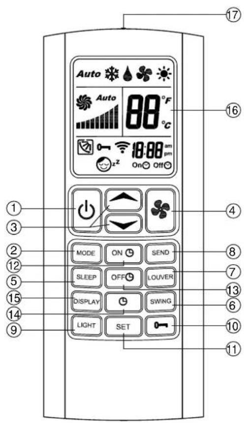
1-ON/OFF
Turning on and off.
2-MODE
Press this button to set the various operating modes: automatic (AUTO), cooling (COOL), dehumidification (DRY), heating (HEAT) and ventilation (FAN).
3-TEMP and TEMPERATURE (°C)
Temperature control buttons (16 to 30^
Use these buttons to set the temperature you wish to have in the room, TEMP to increase the temperature and TEMP to decrease it. When the two TEMP and TEMP buttons are pressed at the same time the unit of temperature measurement changes between ^ C and ^
4-FAN
Press this button to select the fan speed: automatic (AUTO), low (LOW), medium (MED) and high (HIGH).
5-SLEEP
Button to enable the night comfort function (SLEEP).
6-SWING
Press this button to enable to swinging of the horizontal blades.
7-LOUVER
Press this button to regulate the vertical air flow, with 4 fixed positions plus swinging blades.
8-SEND -
Press this button to transmit the parameters shown on the display to the unit.
9-LIGHT
Hold the LIGHT button for 3 sec switches the display light on or off.
10-LOCK
Hold the LOCK button for 3 sec to lock or unlock all the other buttons.
11-SET
Press this button to save the clock or the timer on/off settings.
12-TIMER ON
Press this button to set the timer on function.
13-TIMER OFF
Press this button to set the timer off function.
14-CLOCK
Press this button to set the clock function.
15 - DISPLAY
Press this button to turn the remote control display on or off.
16-LCD DISPLAY
Shows the settings of the fan coil unit.
17 - TRANSMITTER
Sends the signals to the fan coil unit receiver. It must be pointed at the receiver.
LIQUID CRySTAL DISpLAy
With the remote control on (ON), the display shows the settings of the unit, with the remote control off (OFF) the display is off and only displays the timer for the programmed activation (if active).
1-OpERATING MODE
Shows the operating mode:
AUTO automatic
FAN ventilation
COOL cooling
DRY dehumidification
HEAT heating
2-fAN SpEED
Display of the three fan speeds and the automatic speed control:
AUTO automatic speed control
HIGH high speed
MED medium speed
LOW low speed
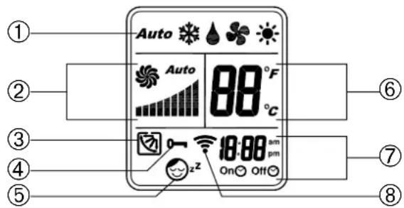
3-HORIZONTAL BLADE pPOSITION
Displays the four fixed positions of the horizontal blades and oper
ation with the blades moving.
4-kEy LOCk
Shows the key lock function is activate.
5-SLEEpPROGRAMME
Shows the night comfort function SLEEP is active.
6-TEMPERATURE (^) OR (^)
Displays the set point temperature value in ^ C or ^o F
7-TIMER
Indicates that the timer programmed on or off function has been activated.
8 - TRANSMISSION INDICATOR
Appears every time a button is pushed and it indicates the transmission of the signal.
USE OF THE REMOTE CONTROL
- Point the remote control transmitter towards the fan coil receiver while the settings are being programmed.
- To be able to carry out any operation or change of the settings from the remote control, the unit must be powered.
- When a signal is received correctly by the FCW it will emit a beep. If you do not hear the sound, press the remote control button again.
- Obstacles must not be placed between the transmitter and the receiver (e.g. furniture or curtains) to ensure proper operation.
- The remote control is able to transmit effectively up to 7 metres from the fan coil unit receiver.
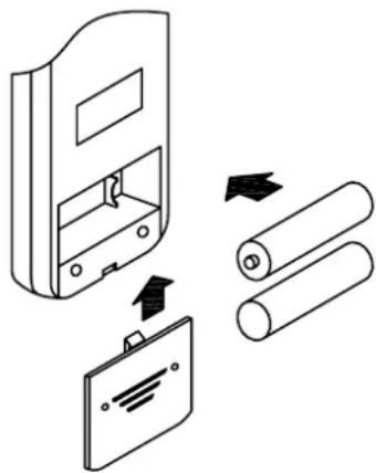
pREpARATION OF THE REMOTE CONTROL
- Open the battery cover by pressing slightly in the direction of the arrow.
- Insert two 1.5 Volt high-performance alkaline batteries LR 03 (AAA), being careful not invert the polarity.
- Close the battery cover.
IMpORTANT
The two control types, wired control panel and remote control, cannot be used at the same time on the same fan coil unit.
- The batteries have an average life of 10 months when used normally.
- The two batteries must be identical and must be changed at the same time.
- Remove the batteries from the remote control unit if you envisage the units not being used for long periods.
- When the remote control only works near the fan coil unit, it is time to replace the batteries.
- Do not fix the remote control bracket near a source of heat or in direct sunlight. Avoid exposing the remote control to excessive humidity or knocks (it might break, become deformed, or lose its colour).
- Do not place the remote control near electronic equipment because it could interfere with the unit's proper operation.
PFW2 - WIRED CONTROL PANEL
IMPORTANT
Note for FCW series with microprocessor controller:
- The two control types, wired control panel (PFW2) and remote control (TLW2), cannot be used at the same time on the same fan coil unit.
- If the fan coil is off, all the previous settings made are kept in the memory except for the TIMER setting and SLEEP mode.
- If the fan coil is turned on using the (ON/OFF) key, the TIMER setting and SLEEP mode are cancelled.
1-ON/OFF
Turning the unit on and off.
2-MODE
Press this button to set the various operating modes: automatic (AUTO), cooling (COOL), heating (HEAT) and ventilation (FAN).
3-SLEEP
Press this button to enable the night comfort function (SLEEP).
4-KEY LOCK
Press the and MODE buttons for 3 seconds to activate or disactivate the key lock function. The LED will light up to show the key lock is activated.
5-LCD DISPLAY
6-FAN
Press this button to select the fan speed: automatic (AUTO), low (LOW), medium (MED) and high (HIGH).
7-TEMPERATURE (^)
Temperature control (16 to 30^ - Use these buttons to set the temperature you wish to have in the room, to increase the temperature and to decrease it.
8-TIMER
Timer control buttons (1 to 24 hours). Use these buttons to set the time in hours, to increase the time and to decrease it.
Programmed turning off: with the fan coil unit on it sets and displays the operation time before the programmed turn off.
Programmed turning on: with the fan coil unit off (but powered) it sets and displays the hours off before the programmed turn on.
9-SWING-HORIZONTAL BLADES
Press this button to control the vertical air flow. The first press starts the blades swinging. The second press stops the blades in the current position. To re-start the blades swinging press the SWING button again.
DISPLAY ON THE WIRED CONTROL PANEL
LED Indications
Operating mode:
COOL Cooling
DRY Dehumidification
HEAT Heating
FAN Ventilation
Fan speed:
Display of the three fan speeds and the automatic control of the speed:
AUTO Automatic speed control
HIGH High speed
MED Medium speed
LOW Low speed
Functions:
TIMER Timer function is activated
SWING Horizontal blades swinging
SLEEP Night comfort function activated
LOCK Keys are locked
LCD DISPLAY
Temperature (^)
Displays the value of the temperature set point in ^ C (from 16^ to 30^
Timer (hour)
Displays the value of hours (Hr) of the timer, when it is active.
With the fan coil unit on it displays the operation time before the programmed turn off.
With the fan coil unit off (but powered) it displays the hours off before the programmed turn on
AUTOMATIC pPROGRAMME (AUTO)
The programme requires the system to circulate chilled or hot water.
1) pRESS THE ON/Off OR q
The fan coil unit comes on. The fan coil unit will automatically switch on in Cool mode, Heat mode or in the dead band (waiting) depending on the water temperature.
2) pRESS THE MODE kEy
Press the MODE key repeatedly until the word AUTO appears on the display (TLW2) or the LEDs on wired control panel (PFW2) turns on HEAT and COOL.
3) pRESS THE fAN \* OR fANS
When the FAN key is pressed repeatedly, the system can move to the minimum speed (LOW), medium speed (MED) and high speed (HIGH) or to the (AUTO) speed controlled by the microprocessor.
4) pRESS THE OR KEYS TO SET THE TEMPERATURE
The key with the symbol allows increases of 1^
- The key with the symbol allows decreases of 1^
The display shows the set point value between 16 and 30^
5) TO DIRECT THE AIR fLOw
To ensure optimum air distribution, adjust the horizontal blades and the vertical blades in such a way that the air flow does not hit people directly. The vertical air flow blades must be set manually before starting up the motorised blades.
Never adjust the motorised horizontal blades manually.
When the LOUVER key is pressed repeatedly, the horizontal blade is adjusted to 4 fixed blade positions, then a swinging blade movement will begin. If you wish to stop the blade in a particular position, press the LOUVER key.
When the SWING key is pressed a swinging blade movement will begin. If you wish to stop the blade in a particular position, press the SWING key again.
6) pRESS THE SEND kEy (TLw2)
To transmit the new parameters shown on the LCD to the main control unit.
WHAT HAppENS WHEN THE AUTOMATIC PROGRAMME IS SET
With AUTO programme, the control system decides the type of operation (COOL or HEAT) on the basis of the water and room temperature and set point.
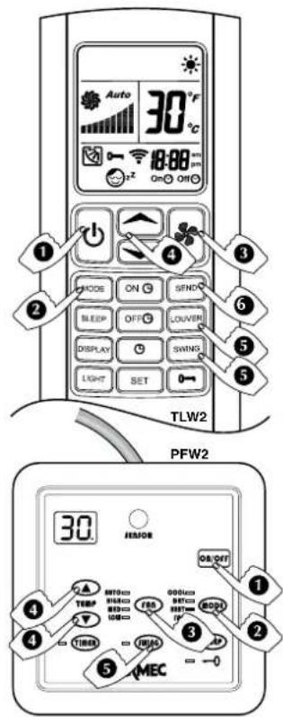
HEATING pPROGRAMME (HEAT)
The programme requires the system to circulate hot water.
1) pRESS THE ON/Off OR
The fan coil unit comes on and the display on the unit switches on.
2) pRESS THE MODE kEy
Press the MODE key repeatedly until the word HEAT appears on the display (TLW2) or the LEDs on wired control panel (PFW2) turns on HEAT.
3)pRESS THE OR KESTO CONTROL THE TEMPERATURE
-
The key with the symbol allows increases of 1^
-
The key with the symbol allows decreases of 1^
The display shows the set point value between 16 and 30^
4) pRESS THE fAN OR rhyS
When the FAN key is pressed repeatedly, the system can move to the minimum speed (LOW), medium speed (MED) and high speed (HIGH) or to the (AUTO) speed controlled by the microprocessor.
5) TO DIRECT THE AIR fLOW
To ensure optimum air distribution, adjust the horizontal blades and the vertical blades in such a way that the air flow does not hit people directly. The vertical air flow blades must be set manually before starting up the motorised blades.
Never adjust the motorised horizontal blades manually.
When the LOUVER key is pressed repeatedly, the horizontal blade is adjusted to 4 fixed blade positions, then a swinging blade movement will begin. If you wish to stop the blade in a particular position, press the LOUVER key.
When the SWING key is pressed a swinging blade movement will begin. If you wish to stop the blade in a particular position, press the SWING key again.
6) pRESS THE SEND kEy (TLw2)
To transmit the new parameters shown on the LCD to the main control unit.
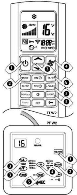
COOLING pPROGRAMME (COOL)
The programme requires the system to circulate chilled water.
1) PRESS THE ON/Off OR q
The fan coil unit comes on. The fan coil unit automatically starts in cooling mode.
2) pRESS THE MODE kEy
Press the MODE key repeatedly until the word COOL appears on the display (TLW2) or the LEDs on wired control panel (PFW2) turns on COOL.
3) pRESS THE kEyS OR CONTROL THE TEMPERATURE
The key with the symbol allows increases of 1^
- The key with the symbol allows decreases of 1^
The display shows the set point value between 16 and 30^
4) pRESS THE fAN kEy OR fan
When the FAN key is pressed repeatedly, the system can move to the minimum speed (LOW), medium speed (MED) and high speed (HIGH) or to the (AUTO) speed controlled by the microprocessor.
5) TO DIRECT THE AIR fLOw
To ensure optimum air distribution, adjust the horizontal blades and the vertical blades in such a way that the air flow does not hit people directly. The vertical air flow blades must be set manually before starting up the motorised blades.
Never adjust the motorised horizontal blades manually.
When the LOUVER key is pressed repeatedly, the horizontal blade is adjusted to 4 fixed blade positions, then a swinging blade movement will begin. If you wish to stop the blade in a particular position, press the LOUVER key.
When the SWING key is pressed a swinging blade movement will begin. If you wish to stop the blade in a particular position, press the SWING key again.
6) pRESS THE SEND kEy (TLw2)
To transmit the new parameters shown on the LCD to the main control unit.
fAN pPROGRAMME (fAN)
1) pRESS THE ON/Off OR kessort
The fan coil comes on and the display is switched on.
2) pRESS THE MODE kEy
Press the MODE key repeatedly until the word FUN appears on the display (TLW2) or the LEDs on wired control panel (PFW2) turns on FUN.
3) pRESS THE fAN \* OR rans
When the FAN key is pressed repeatedly, the system can move to the minimum speed (LOW), medium speed (MED) and high speed (HIGH) or to the (AUTO) speed controlled by the microprocessor.
4) TO DIRECT THE AIR fLOW
To ensure optimum air distribution, adjust the horizontal blades and the vertical blades in such a way that the air flow does not hit people directly. The vertical air flow blades must be set manually before starting up the motorised blades.
Never adjust the motorised horizontal blades manually.
When the LOUVER key is pressed repeatedly, the horizontal blade is adjusted to 4 fixed blade positions, then a swinging blade movement will begin. If you wish to stop the blade in a particular position, press the LOUVER key.
When the SWING key is pressed a swinging blade movement will begin. If you wish to stop the blade in a particular position, press the SWING key again.
5) pRESS THE SEND kEy (TLw2)
To transmit the new parameters shown on the LCD to the main control unit.
OpERATING IN JUST VENTILATION MODE
This programme is used to move the room air and avoid stagnation. The ventilation programme is particularly indicated as a support to heating systems without fans, as when a stove is used to heat the room. All the hot air gathers by the ceiling. When the unit is set in ventilation mode, the hot air is distributed uniformly throughout the room.
DEHUMIDIFICATION PROGRAMME (DRY)
The programme requires the system to circulate chilled water.
1) PRESS THE ON/OFF OR OR ON WITH OR KEYS on/off
The fan coil comes on and the display is switched on.
2) PRESS THE KEY MODE MODE OR MODE
Press the MODE key repeatedly until the word DRY appears on the display (TLW2) or the LEDs on wired control panel (PFW2) turns on DRY.
3) PRESS THE KEYS OR CONTROL THE TEMPERATURE
-
The key with the symbol allows increases of 1^
-
The key with the symbol allows decreases of 1^
The display shows the set point value between 16 and 30^
4) TO DIRECT THE AIR FLOW
To ensure optimum air distribution, adjust the horizontal blades and the vertical blades in such a way that the air flow does not hit people directly. The vertical air flow blades must be set manually before starting up the motorised blades.
Never adjust the motorised horizontal blades manually.
When the LOUVER key is pressed repeatedly, the horizontal blade is adjusted to 4 fixed blade positions, then a swinging blade movement will begin. If you wish to stop the blade in a particular position, press the LOUVER key.
When the SWING key is pressed a swinging blade movement will begin. If you wish to stop the blade in a particular position, press the SWING key again.
5) PRESS THE SEND KEY (TLW2)
To transmit the new parameters shown on the LCD to the main control unit.
The fan coil unit will always operate at minimum speed.
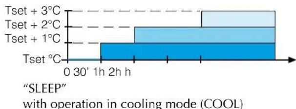
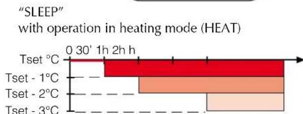
NIGHT COMFORT FUNCTION (SLEEP)
The SLEEP programme operates regardless of the time of day. Normally it is used during the night time hours.
1) PRESS THE ON/OFF OR ONWITH OR KEYS on/off
The fan coil unit comes on and display is switched on.
2) PRESS THE MODE KEY
This can only be activated with AUTO, HEAT and COOL programmed.
3) PRESS THE KEYS OR CONTROL THE TEMPERATURE
The key with the symbol allows increases of 1^ .
The key with the symbol allows decreases of 1^
The display shows the set point value between 16 and 30^
4) PRESS THE FAN KEY OR fan
When the FAN key is pressed repeatedly, the system can move to the minimum speed (LOW), medium speed (MED) and high speed (HIGH) or to the (AUTO) speed controlled by the microprocessor.
The temperature set point is automatically adjusted to ensure comfortable conditions whilst saving energy.
TURN ON pPROGRAMMED By THE TIMER
1) TURNONWITH k8s/off
- Set the required conditions (MODE, FAN, TEMP) on the remote control that you want active when starting the unit.
Turn off with keys or on/off
2) ACTIVATE THE TIMER ON WITH OROKeyS TIMER
3) SET THE TIMER ON WITH OR
The key with the symbol allows increases of 1 hour
The key with the symbol allows decreases of 1 hour
The display only shows the hours the unit remains off before the unit is turned on, TLW2 from 1 to 18 hours,
PLW2 from 1 to 24 hours,
The number is updated every hour until the unit turns on.
At the time of switching on the unit:
-
a beep indicates that the unit has started
-
the display will show the conditions previously chosen in point 1)
At the time the unit is programmed to come on, the fan may not come on:
-
because the space temperature is already within the programmed parameters
-
because the temperature of the water is not appropriate for the operation mode required
-
because during the programmed standby hours the unit's power went down.
4) pRESS THE SET OR TIMER kEyS TO CONFIRM THE TIMER
5) pRESS THE SEND kEy (TLw2)
To transmit the new parameters shown on the LCD to the remote control.
TO CANCEL THE TIMER SETTING
- TLW2: Press the OFF key to cancel the timer setting
- PFW2: Press the TIMER key for 3 seconds to cancel the timer setting.
- Press the or on/off key to manually turn ON the unit while the timer is programmed.
TURN Off pPROGRAMMED By THE TIMER
1) TURNONWITH OR koe/ort
- Set the conditions (MODE, FAN, TEMP) on the remote control
2)TO ACTIVATE THE TIMER Off with ON OR TMGER
3) SET THE TIMER Off with OR REs
The key with the symbol allows increases of 1 hour
The key with the symbol allows decreases of 1 hour
The display shows the operating mode and the programmed running hours before the unit is turned off,
TLW2 from 1 to 18 hours,
PLW2 from 1 to 24 hours,
The number is updated every hour until the unit turns off.
Before the programmed turn off a beep will be emitted from the unit.
At the time the unit is programmed to turn off the unit may not switch off if the power has been interrupted during the programmed running time.
4) pRESS THE SET OR TIMER kEyS TO CONFIRM THE TIMER
5) pRESS THE SEND kEy (TLw2)
To transmit the new parameters shown on the LCD to the remote control.
TO CANCEL THE TIMER SETTING
- TLW2: Press the OFF key to cancel the timer setting
- PFW2: Press the TIMER key for 3 seconds to cancel the timer setting.
- Press the or on/off key to manually turn OFF the unit and the timer programme is cancelled.
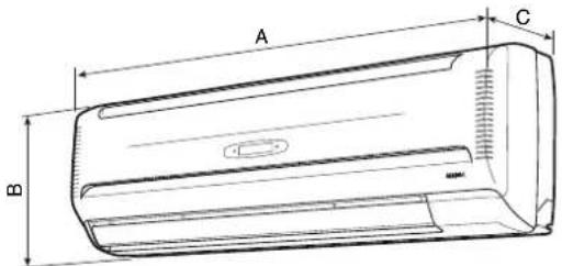
| A B C | |||
| FCW212V - FCW212VN | 880 29 | 180 | |
| FCW213V - FCW213VN | |||
| FCW21VL - FCW21VLN | |||
| FCW312V - FCW312VN | 990 30 | 180 | |
| FCW313V - FCW313VN | |||
| FCW31VL - FCW31VLN | |||
| FCW412V - FCW412VN | 1172 3 | 210 | |
| FCW413V - FCW413VN | |||
| FCW41VL - FCW41VLN | |||
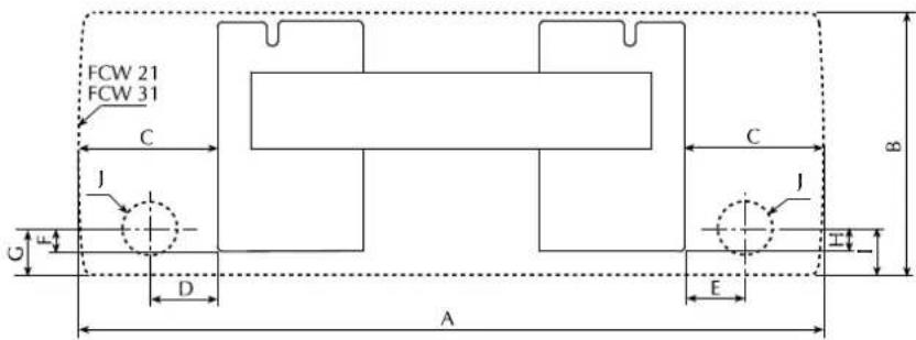
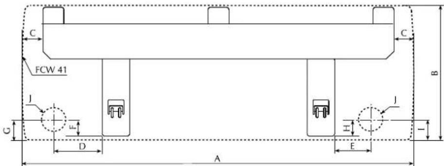
| FCW A B C D E F G H I | J | ||||||||
| 212V - 213V - 21VL - 212VN - 213VN - 21VLN | 880 | 298 | 190 | 90 | 68 | 21 | 36 | 25 | 40 |
| 312V - 313V - 31VL - 312VN - 313VN - 31VLN | 990 | 305 | 191 | 91 | 69 | 24 | 46 | 28 | 50 |
| 412V - 413V - 41VL - 412VN - 413VN - 41VLN | 1172 | 360 | 139 | 210 | 115 | 21 | 42 | 25 | 46 |
INSTALLATION OF THE UNIT
WARNING: before carrying out any work ensure the individual has the appropriate personal protection.
WARNING: check that the power supply is disconnected before performing operations on the unit.
WARNING: wiringconnections, installation of the fan coil unit and relevant accessories should be performed by a technician who has the necessary technical and professional expertise to install, modify, extend and maintain systems and who is able to check the system for the purposes of safety and
correct operation.
In the specific case of electrical connections, the following must be checked:
-
Measurement of the electrical system insulation resistance.
-
Continuity test of the protective wiring.
If the fan coil unit operates continuously in cooling mode in a room with high relative humidity, condensate might form on the air discharge. This condensate might be deposited on the floor and on any objects underneath.
To prevent the formation of condensation on the exterior of the unit while the fan is operating, the average water temperature should not drop below the operating limits shown in the manual determined by the room temperature and humidity conditions. These limits refer to unit operation with fan at minimum speed.
In order to avoid air stratification and therefore achieve better mixing it is advised not supply the fan coil unit with water hotter than 65^ . The use of very hot water could cause creak
ing due to the thermal expansion of the different components (plastics and metals). This does not cause damage to the unit if the maximum operating temperature is not exceeded.
Instructions essential for the proper installation of the equipment are shown here.
The final touches to all the operations are however left to the experience of the installation engineer in accordance with the specific needs.
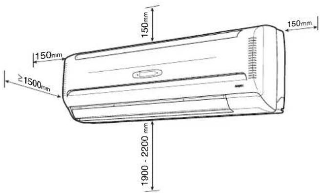
The FCW fan coil unit must be installed in such a position that the air can be distributed throughout the room and that there are no obstacles (curtains or objects) to the passage of the air from the intake. The unit must be arranged in such a way as to make
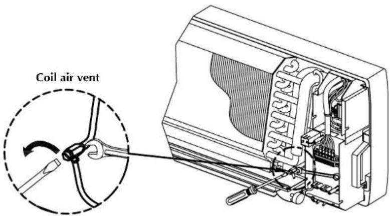
ordinary maintenance easy (filter cleaning) and special maintenance, as well as the access to the air vent valve on the heat exchanger coil at a height of 190 to 220cm .
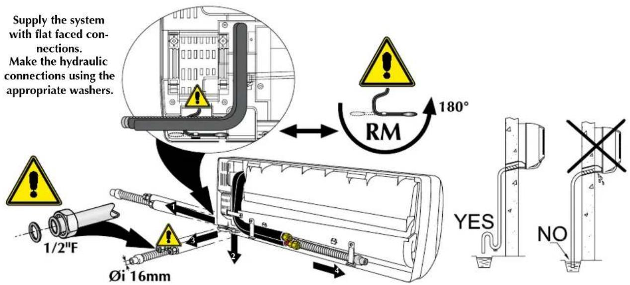
Hydraulic connections:
Female diam. 1 / 2^ with flat faced flare connections. The direction of the water flow is indicated on the pipes of the unit.
Condensate drain connections:
FCW 21 - 31 and 41: Female with internal diameter of 16mm
The supply and return pipes must be equally sized, made of copper with a minimum diameter of 1/2'' , suitably insulated to avoid heat dispersion and dripping during cooling operation.
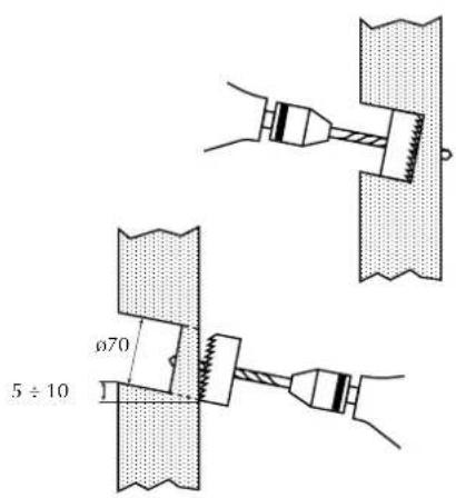
The water and condensate drainage pipes and the electrical circuit wiring on the wall must be installed beforehand. The diameter of the hole for the connections must be at least 70~mm and the piping positioned in such a way as to maintain an adequate inclination along the entire route ( .1%) , to ensure evacuation of the condensate produced in the cooling operation of the pipe.
the fan coil unit.
The condensate drainage system must be correctly sized. To avoid unpleasant smells a trap is recommended if the condensate is connected to the sewage system.
The service hole for the piping can be located on the right or left of the unit. The support wall must be sturdy and not subject to vibrations.
Do not install the unit near sources of heat, vapour or flammable gas.
Do not install in a position exposed to direct sunlight.
Installation
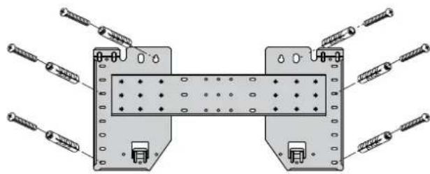
To install the unit, proceed as follows: - Put the template on the wall, fixing it solidly with at least six or more screws or expansion blocks of a type that is adequate for the thickness of the fixing wall, through holes near the edge of the template.
The template must be fixed flush to the wall, perpendicular to the floor and perfectly level. Failure to respect these conditions will cause water to drip out of the drain tray. - Remove the cabinet.
- The FCW unit permits 4 connection possibilities.
For connections through the wall make a hole with a diameter of 70~mm inclined downwards by 5-10 mm.
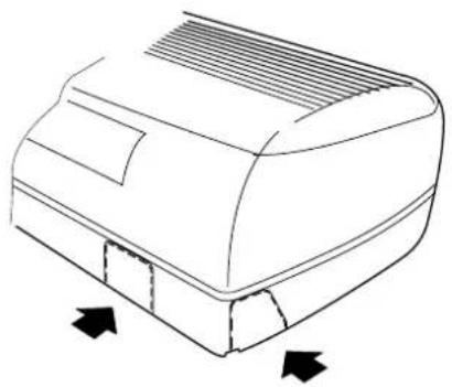
For connections sideways and downwards, remove the knock-outs of the cabinet in the direction of the pipes.
- Carry out the electrical connections as shown on the wiring diagram.
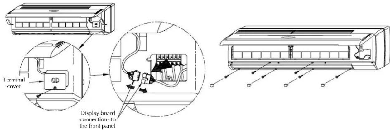
If you intend to control the fan coil unit with the PFW2 wired control panel make the connection with the unit as indicated in the wiring diagram: remove the connector of the Infra Red receiver from the circuit board of the unit and connect the wired control panel to it. The cable is 4 metres long.
- Make the water connections. If the
pipe is repeatedly bent it may break.
The unit's pipes indicate the direction of the water flow
- Connect the condensate drain outlet to the drainage line and make sure it works properly.
- Insulate the pipes properly.
- Position the FCW unit on the template after passing the pipe through the hole or in the channelling in the wall. Check that the fan coil is level horizontally and vertically.
- When all the installations have been
completed (electrical and hydraulic connections, fan coil unit fixing and condensate drain connection) close the hole in the wall with a suitable filler.
- Vent the coil using the air valve provided.
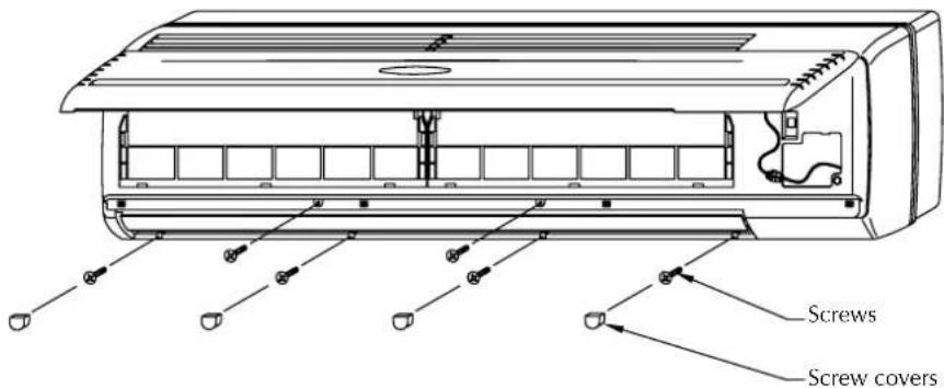
- Complete the refitting of the components of the unit paying attention that the debris from the materials used for the installation do not block the fan or obstruct the filters or the grilles.
After installation perform a functional test of the fan coil unit.
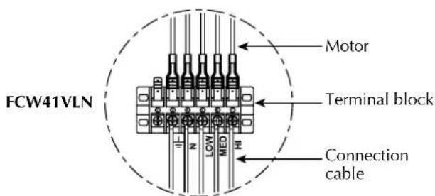
ELECTRICAL WIRING
WARNING: check that the power supply is disconnected before performing operations on the unit.
The unit must be connected directly to an electrical outlet or to an independent circuit.
Provide a 230V (± 10%) power supply. To protect the unit against short circuits, fit a circuit breaker of max. 2A 250V to the power line with a
minimum contact opening distance of 3mm
The electrical power cable must be of the H07 V-K or N07 V-K type with 450/750V insulation rating if inside a tube or conduit. Use cables with double H5vv-F type insulation for exposed cable installation.
Follow the wiring diagram supplied with the equipment and shown in this
document when making the connections.
Ensure that the installation is wired in compliance with the laws and standards in force, and with the instructions in this manual.
All the parts and materials supplied on site must comply with the local laws and regulations.
Electrical wiring
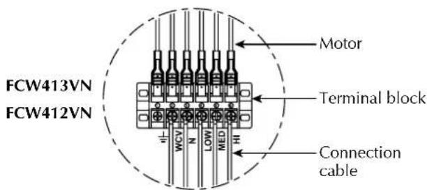
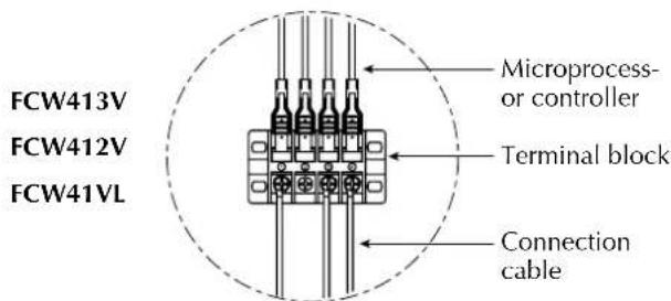
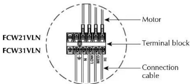
| FCW_2V FCW_3V FCW_VL | FCW_2VN FCW_3VN FCW_VLN | |
| IG 2A | ||
| Cable cross section 1.5mm 2 | ||
WARNING
The unit must be correctly earthed; incorrect connection could result in electric shocks or fires.
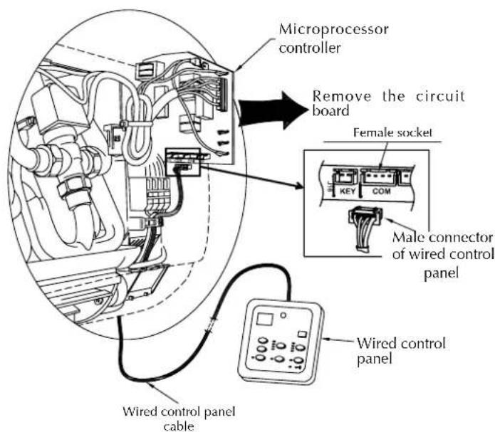
INSTALLATION OF PFW2 WIRED CONTROL PANEL (ACCESSORY)
Accessory indispensable for the functioning of the fan coil unit. Alternative to the remote control TLW2. The two control systems cannot be used together.
A PFW2 wired control panel can only control one fan coil unit. The panel can be fixed directly to the wall with two screws or a rectangular electrical box. The panel cable is 4 metres long and is fitted with connector (B) for connection to the fan coil circuit board as shown in the wiring diagrams. To install the wired control panel it is necessary:
- to disconnect the connector (A) of the
infrared receiver from the circuit board inside the fan coil unit.
- connect connector (B) of the wired control panel to the circuit board connector now vacant.
The PFW2 makes it possible to set the operating parameters of the unit and these parameters are shown on a liquid crystal display, making programming operations easier.
Avoid installing the panel in positions where it is directly exposed to the sun light.
PFW2
Cher client,
INDICATIONS AVEC LED
INDICATIONS AVEC LED
Affichea cristaux liquides
4) vITESSE DEVENTILATION, TOUCHE O ran
3) vITESSE DEVENTILATION, TOUCHE # O ran
DONNÉES DIMENSIONNELLES [mm]
![Aermec FCW 312V - DONNÉES DIMENSIONNELLES [mm] - 1](/content/2026/02/375409/images/53c3dcc0be88c349af192fba647b9f52c7c01514931acbce269ddf62a8f8b986.jpg)
| A B C | |||
| FCW212V - FCW212VN | 880 29 | 98 180 | |
| FCW213V - FCW213VN | |||
| FCW21VL - FCW21VLN | |||
| FCW312V - FCW312VN | 990 30 | 180 | |
| FCW313V - FCW313VN | |||
| FCW31VL - FCW31VLN | |||
| FCW412V - FCW412VN | 1172 36 | 210 | |
| FCW413V - FCW413VN | |||
| FCW41VL - FCW41VLN | |||
![Aermec FCW 312V - DONNÉES DIMENSIONNELLES [mm] - 2](/content/2026/02/375409/images/2c333ebd93f7871f01884d42ca7c7b943cdadaa03c3cd91157bdb3f93910b68d.jpg)
![Aermec FCW 312V - DONNÉES DIMENSIONNELLES [mm] - 3](/content/2026/02/375409/images/6f688b15ac35e90c8ea845b441bfbe66b330a0ec862dd7d9185b35631911c782.jpg)
![Aermec FCW 312V - DONNÉES DIMENSIONNELLES [mm] - 4](/content/2026/02/375409/images/1af086bb660329d218df0f41c38481182ad63ab82f4bdafa820e1a6d4bf75fae.jpg)
| FCW A B C D E F G H I J | ||||||||||
| 212V - 213V - 21VL - 212VN - 213VN - 21VLN | 880 | 298 | 190 | 90 | 68 | 21 | 36 | 25 | 40 | Ø70 |
| 312V - 313V - 31VL - 312VN - 313VN - 31VLN | 990 | 305 | 191 | 91 | 69 | 24 | 46 | 28 | 50 | Ø70 |
| 412V - 413V - 41VL - 412VN - 413VN - 41VLN | 1172 | 360 | 139 | 210 | 115 | 21 | 42 | 25 | 46 | Ø70 |
INSTALLATION DE L'UNITE
VMF (System Variable Multi Flow)
5) PRESIONE LA TECLA SLEEP SLEEP O SLEEP
6) PRESIONE LA TECLA "SEND" (TLW2)
Components not supplied
Composants non fournis
BERGAMO (split system)
BOLOGNA (split system)
AERMEC participates in the Eurovent programme: fCU
Products covered by the programme can be found on the site www.eurovent-certification.com
Technical data shown in this booklet are not binding.
Aermec S.p.A. shall have the right to introduce at any time whatever modifications deemed necessary to the improvement of the product.