PXA E - Air Conditioning Aermec - Free user manual and instructions
Find the device manual for free PXA E Aermec in PDF.

User questions about PXA E Aermec
0 question about this device. Answer the ones you know or ask your own.
Ask a new question about this device
Download the instructions for your Air Conditioning in PDF format for free! Find your manual PXA E - Aermec and take your electronic device back in hand. On this page are published all the documents necessary for the use of your device. PXA E by Aermec.
USER MANUAL PXA E Aermec
ELECTRONIC CONTROL PANEL FOR FAN COILS
WALL-MOUNTED INSTALLATION
PANNEAU DE COMMANDE ELECTRONIQUE POUR
VENTILO-CONVECTEURS
INSTALLATION MURALE
ELEKTRONISCHE BEDIENTAFEL FÜR
GEBLASEKONVEKTOREN
ZUR WANDMONTAGE
TABLEERO DE MANDOS ELECTRONICO PARA FAN COILS
Congratulations for purchasing the PXA E Aermec electronic control panel with thermostat. Made with top quality materials rigorously abiding by safety rules, the "PXA E" is easy to use and will be by your side for many years to come.
The PXA E regulation thermostats are control panels for fan coils for wall-mounted installation.
They control the fan coil function in accordance with the mode set, the room temperature and water temperature in the circuit to maintain the set temperature in the room.
The panels must be wall-mounted; they must be used on four- or two-pipe plus PLASMACLUSTER® purifier systems with the possibility of
connecting two On - Off valves to cut off the supply of water to the coils or one valve and a air purifier.
Each control panel can control a single fan coil.
The control panel only consists of mains voltage (230V) electrical circuits; all the inputs for the probes and controls must therefore be correspondingly insulated for this voltage.
The valve servo commands must also be scaled for 230V
PXA meets the requirement of the Low Voltage directives 73/23 (EN 60730-1, EN 60730-2-9, EN 60335-1) and electromagnetic compatibility directive 89/336 (EN 61000-4-1, EN 55011, 55022, 55014).
The panel may only be opened and installed by specialised personnel.
Cut off the supply voltage before removing the lid of the control panel. Contact with live components can cause dangerous electric shocks.
This is particularly true also for the setting of contacts on the Sw1 and Sw2 cut outs.
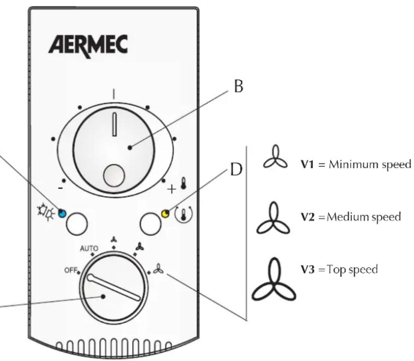
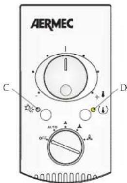
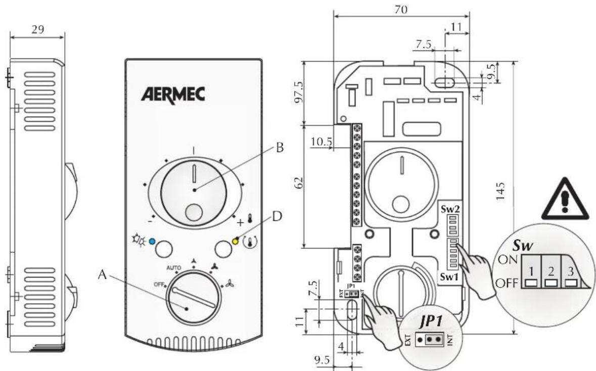
The panel comprises:
- (A) on-off selector switch and ventilation speed;
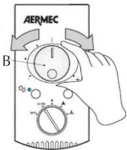
(B) temperature selector; - (C) blue / red/ fuchsia leds, operating modes (Cooling/ Heating/
Antifreeze/Autotest) - (D) yellow led, fan coil operation, Autotest.
OPERATION
The thermostat's job is to keep the temperature set on selector (B) constant in the room.
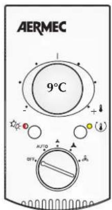
Frost Protection, with selector (A) in the OFF position, prevents rooms that are unoccupied for long periods from falling to temperatures below 7^ that would make them hard to heat when they are used again. If the fan coil is fed with warm water it will start in AUTO until the room temperature is 9^ .
The Frost Protection function must be programmed by the installation engineer.
All Off, selector (A) in the OFF position, the fan coil is completely off.
VENTILATION
In the two-pipe system, the thermostat makes it possible to enable the heating ventilation only if the temperature of the water exceeds 35^ or 39^ (programmable in the installation phase); in the same way the ventilation in cooling mode is only enabled if the water temperature is less than 17^ or 22^ (programmable in the installation mode).
The ventilation is delayed compared with the start and turn off commands.
The functions described on the one hand prevent unwanted cold variation in winter functioning and on the other allow all the terminals to come on and go off depending on the temperature of the water.
The ventilation mode is set with selector (A).
Manual mode (selector in position V1, V2, V3) the fan uses On-Off cycles on the speed selected.
Automatic mode (selector in AUTO position) the fan speed is managed by the microprocessor of the PXA.
The delay between opening or closing of the warm water valve and the turning on or off of the fan can last for up to 2^40^
AUTOMATIC CHANGE OVER : AIR SIDE
The control makes it possible to automatically set the fan coil functioning mode at hot or cold.
-
In the two-pipe no valve systems or those with probe up line from the valve, the functioning mode change is determined by the temperature of the water circulating in the plant.
-
In the four-pipe no valve systems or with probe up line of the valve, the functioning mode change is determined by the temperature of the water circulating in the plant if this is at a value higher than the enabling threshold. If the temperature of the water circulating is lower than the disabling threshold, the functioning mode change is determined by the difference between the temperature measured in the room and the set temperature.
-
In two-pipe systems with probe downline of the valve and in all the systems without water temperature probes, the change of functioning mode is determined by the difference between the temperature measured in the room and the set temperature.
USE
Controls
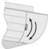
To turn on the FCX U - FCS U - Omnia HL S / SM - Omnia UL S / MS fan coils first open the fins.
English
Speed selector (A)
OFF Power down command. Standstill status might be of two types, Frost Protection or All Off (contact the installation engineer to know the set configuration).
All Off: The fan coil is turned off.
Frost Protection: The fan coil is off but can start again in heating mode if the room temperature falls below 7^ (the boiler must be on).
AUTO The thermostat keeps the set temperature by changing the fan speed automatically.
The thermostat keeps the set temperature using the minimum, medium and top speeds of the fan.
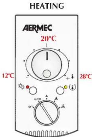
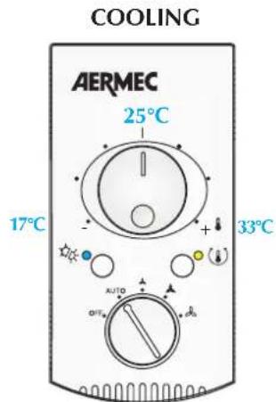
Temperature selector (B)
This permits the required temperature to be set. The temperature corresponding with the selector set at the central position depends on the set functioning mode (Heating 20^ , Cooling 25^ ). The differences of minimum and maximum temperature with respect to the central position are +8^ and -8^ .
FROST PROTECTION
DISPLAYS
Indicator lights
| (C) (D) | ||||
| Red Blue | Fuchsia | Yellow Functioning | mode | |
| ○ | ○ | ○ | Off ○ | |
| ● | ○ | ○ | Heating | |
| ○ | ● | ○ | Cooling ● | |
| ▷○ | ▷○ | Stand by Heating (water temperature too low) | ||
| ▷○ | ▷○ | Stand by Heating in units with PLASMACLUSTER®(water temperature too low) | ||
| ○ | ● | ● | Stand by Cooling (water temperature too high) | |
| ○ | ● | ● | ● | Stand by Cooling in units with PLASMACLUSTER®(water temperature too high) |
| ▷○ | ▷○ | Antifreeze | ||
| ○ | ○ | ● | Autotest for installation (combination of two colours blinking) | |
| ○ | ○ | ○ | Contact the After-Sales Service | |
= Off
=On
B = Blinking
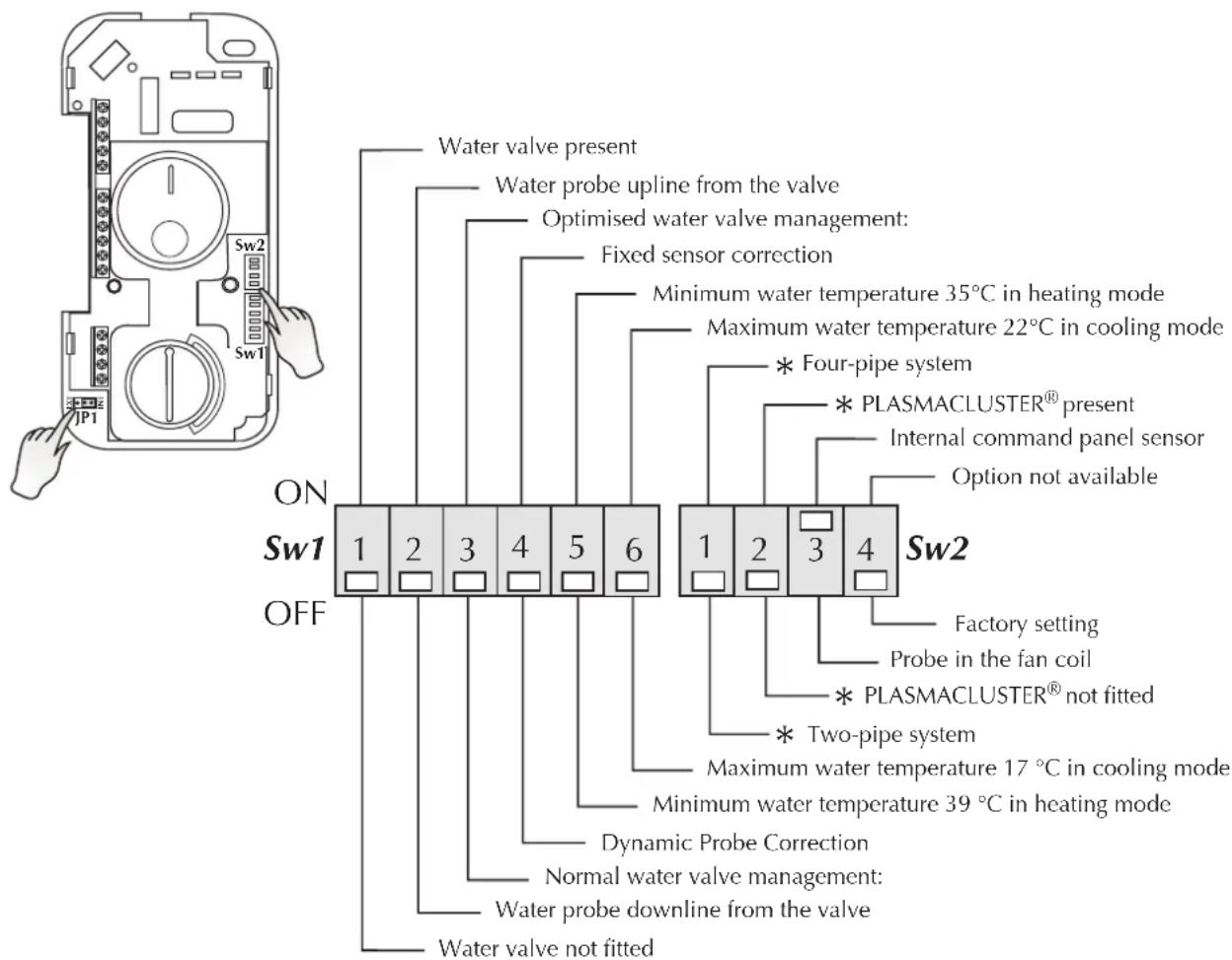
DIP-SWITCH CONFIGURATION
SETTINGS
To be done in the installation phase, only by expert personnel. Some functions are not compatible with each other and, for this reason, limits to Dip-Switch configurations have been set. By turning on or off Dip-Switches inside the thermostat, we get the following functions:
Sw1 Dip 1 (Default OFF)
Water valve fitted:
- Present, set (ON).
- Absent, set (OFF).
Sw1 Dip 2 (Default OFF)
Position of the water temperature probe:
- Water temperature probe positioned up line from the valve, set (ON).
- Water temperature probe positioned down line from the valve, set (OFF).
Sw1 Dip 3 (Default OFF)
Water valve management:
- Optimised, set (ON).
heating mode: valve closure delayed compared to the turning off of the ventilation; cooling: valve closure earlier than the turning off of the ventilation.
- Normal, set (OFF).
Sw1 Dip 4 (Default OFF)
Probe adjustment:
- Fixed adjustment, set (ON).
- Dynamic correction, set (OFF),
calculated on the basis of the water temperature.
Sw1 Dip 5 (Default OFF)
Heating mode enabling temperature:
- Reduced, set (ON).
Minimum water temperature 35^
- Normal, set (OFF).
Minimum water temperature 39^
Sw1 Dip 6 (Default OFF)
Cooling mode enabling temperature:
- Reduced, set (ON).
Maximum water temperature 22^
- Normal, set (OFF).
Maximum water temperature 17^
Sw2 *Dip 1 (Default OFF)
Selection of the type of plant in which the fan coil is included:
- Four-pipe system, set (ON).
- Two-pipe system, set (OFF).
Sw2 *Dip 2(Default OFF)
Presence of PLASMACLUSTER® air purifier:
- Present, set (ON).
- Absent, set (OFF).
Sw2 Dip 3 (Default ON)
Air temperature probe enabling:
- Internal control panel probe,set (ON).
- Probe in fan coil, set (OFF).
Sw2 Dip 4 (Default OFF)
Option not available
NOTES:
* = In the fan coils with two valves installed in four-pipe systems the installation of a PLASMACLUSTER® air purifier is not allowed.
- For the proper functioning of the SA room probe make sure that the Sw2Dip3 is in ON position and the jumper at INT. position.
INSTALLATION
WARNING: before carrying out any work, make sure the electrical power is unplugged.
WARNING: electrical wires, installation of the fan coils and relevant accessories should be performed by a technician who has the necessary technical and professional expertise to install, modify, extend and maintain systems and who is able to check the systems for the purposes of safety and correct operation.
In particular, the following checks are required for electrical wires: - Measurement of the electrical system insulation strength.
- Continuity test of the protection wires.
Instructions essential for the proper installation of the equipment are shown here.
The completion of all the operations in accordance with the specific requirements is however left to the experience of the installation engineer.
The electronic PXA E control panel must be wall mounted.
WALL MOUNTING
You are advised to position the control panel approximately 1.5 metres of the ground in an area that is representative of the temperature of the room. Therefore avoid installing in areas where air stagnates, near doors, windows, heat sources etc.
The control panel may not be fitted on a metal wall unless this is connected to a grounded outlet permanently.
The assembly site must be chosen in such a way that the maximum and minimum room temperature limits are complied with 0 to 45^ (<85% R.H.): furthermore, it must correspond to the command panel's IP20 degree of protection.
To fix the control panel to the wall, proceed as follows:
-
loosen the fixing screw and extract the cover;
-
fix the panel to the wall using the holes for the purpose;
-
push the cable in from the side and carry out the wiring as per the wiring diagrams;
-
set the switches as indicated in the manual;
-
refit the cover being careful of the indicator leds;
the connection cables must be laid inside the device in such a way that the cover fixing screw cannot come into contact with the mains voltage even under anomalous conditions (disconnected wires);
lock into place with the fixing screw.
Warning: check that the installation has been done properly. IT IS necessary to run the Autotest function to check the functioning of the fan, valves and heating element.
CONNECTION WITH THE FAN COIL
Cut off the voltage to the fan coil;
remove the fan coil housing (if there is any);
make the electrical connections to the control board as indicated in the fan coil diagrams;
- reposition the housing; for versions that have them, reconnect the MS power supply microswitch, then fix the screws that were previously removed;
complete the installation of the fan coil.
If the fan coil has a water cut-off valve, the SW probe must be positioned up line from the said valve. If it does not, insert it in the coil and lock it into place with the probe stop.
Warning: the probe is fitted with double insulation because it is subject to a voltage of 230Vac.
To protect the unit against short circuits place a 2A 250V (IG) thermomagnetic switch on the power line.
AUTOTEST FOR INSTALLATION
It is possible to activate an Autotest mode that makes it possible to check the turning on of all the loads.
The Autotest sequence is as follows:
-
Selector switch (A) in the OFF position.
-
Position the temperature selector (B) centrally.
-
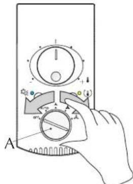
With the selector (A) go through the following sequences quickly: AUTO-OFF-V1-OFF-V2-OFF-V3-OFF.
At this point you enter the AUTOTEST mode (the left-hand led blinks fuchsia).
- With selector (A) in the AUTO position the valves or, if there is one, the PLASMACLUSTER® come on.
The yellow led (D) performs cycles of 1 blink.
-
With the selector (A) in the V1 position minimum speed V1 comes on. The yellow led (D) performs cycles of 2 blinks.
-
With the selector (A) in position V2 medium fan speed V2 comes on. The yellow LED (D) performs cycles of 3 blinks.
-
With selector (A) in position V3 top fan speed V3 comes on. The yellow LED (D) performs cycles of 4 blinks.
The control panel leaves the Autotest mode automatically after a minute.
During the Autotest if temperature selector (A) is at minimum, the yellow led (D) remains permanently on while, if it is at maximum, the yellow led (D) remains off, in both cases the loads are not tested.
- Presente, activer (ON).
- Absente, activer (OFF).
Sw1 Dip 2 (Default OFF)
- Normale, activer (OFF).
Sw1 Dip 4 (Default OFF)
Correction sonde:
-
Correction fixe, activer (ON).
-
Correction dynamique, activer (OFF),
- Normale, activer (OFF).
- Normale, activer (OFF).
CONEXION CON EL FAN COIL
CONNECTION CABLE SPECIFICATIONS Use H05V-K or N07V-K type with 300/500 V insulation if piped or ducted. In the case of exposed wiring, use H05W-F type cable with double insulation.
Wiring diagrams may change for updating. It is therefore necessary to refer always to the wiring diagram inside the units.
Technical data shown in this booklet are not binding.
Aermec S.p.A. shall have the right to introduce at any time whatever modifications deemed necessary to the improvement of the product.