NXW - Air Conditioning Aermec - Free user manual and instructions
Find the device manual for free NXW Aermec in PDF.

| Product type | Water condensing heat pump |
| Brand | Aermec |
| Model | NXW |
| Category | Air conditioning |
| Main functions | Cooling, heating, simultaneous and separate defrost |
| User interface | Control panel with 132x64 pixel graphic display and 6 navigation keys |
| Available menus | Main menu, Quick menu, ON/OFF, Set point, Season, Time slots, Inputs/Outputs, Alarm history |
| Adjustable parameters | Set points in cooling and heating mode, daily time programming, special periods, special days |
| Alarms | History of the last 50 alarms with code, date and description |
| Power supply | Three-phase (not explicitly specified, but typical for this type of equipment) |
| Dimensions (estimated) | Approximately 1200 x 800 x 1000 mm (without guarantee, typical value for a heat pump of this range) |
| Weight (estimated) | Approximately 200-300 kg (depending on configuration) |
| Maintenance and cleaning | Regular cleaning of filters and pressure checks by qualified personnel |
| Safety | High/low pressure protections, flow switches, magnetic-thermal, antifreeze |
| Spare parts and repairability | Compressors, pumps, valves, probes, electronic boards available via Aermec network |
| General information | Automatic restart after power failure with configuration preservation |
Frequently Asked Questions - NXW Aermec
User questions about NXW Aermec
0 question about this device. Answer the ones you know or ask your own.
Ask a new question about this device
Download the instructions for your Air Conditioning in PDF format for free! Find your manual NXW - Aermec and take your electronic device back in hand. On this page are published all the documents necessary for the use of your device. NXW by Aermec.
USER MANUAL NXW Aermec
text_image
26/03/2010 09:02 In.Evap.: 16.7°C Out.Eva.: 20.5°C C1: i esc pGD' user interfacePompa di calore condensata ad acqua Electronic adjustment for water-cooled heat pumps
MANUALE USO USAGE MANUAL
AERMEC
COMPANY QUALITY SYSTEM

ISO 9001:2000 - Cert. n° 0128/5


AERMEC S.P.A.
C E
NXW

text_image
IT GB FR DE ES
INXWUX - 4437800_00 - 1005
natural_image
Illustration of a hand interacting with a touchscreen device (no text or symbols visible)text_image
yes bed next page E2CElectronic adjustment for water-cooled heat pumps
USAGE MANUAL

text_image
AERMEC COMPANY QUALITY SYSTEM S ICIM ISO 9001:2000 - Cert. n° 0128/5 CISQ CERTIFIED QUALITY SYSTEM AERMEC S.P.A.NXW
C €
GB
User interface 3
Menu structure and navigation 4
Use operational procedures ....5
MAIN menu 6
QUICK-MENU parameters....7
ON/OFF MENU parameters....8
Unit switch-on or switch-off from PGD1 panel....8
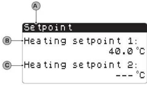
SET POINT MENU parameters....9
Displays the set point currently in use....9
Setting the work set points for COOLING mode 9
Setting the work set points for HEATING mode 9
COOLING/HEATING menu parameters 10
Setting the functioning mode....10
CLOCK/PERIOD MENU parameters 11
Setting the system date and time 11
Setting the daily time periods 11
Setting SPECIAL PERIODS 12
Setting SPECIAL DAYS 12
INPUTS/OUTPUTS MENU parameters 13
HIGH/LOW pressure transducers analogue inputs 13
Evaporator IN/OUT temperature analogue inputs 13
Condenser OUTPUT temperature analogue inputs 13
Condenser INPUT temperature analogue inputs 14
HIGH/LOW pressure pressure switch status digital inputs 14
Remote commands digital inputs 14
Compressor magnet circuit breaker flow switch digital inputs 15
Compressor 2 magnet circuit breaker digital inputs and compressor phases ...... 15
Evaporators pump magnet circuit breaker digital inputs 15
Condenser flow switch digital inputs 16
Compressors digital outputs 16
Condenser pumps digital outputs 16
Anti-freeze resistance and compressor phases alarm digital outputs ....17
Evaporator pump digital outputs 17
Solenoid valves digital outputs 17
4-way valves digital outputs 18
Historical ALARMS....19
Example of historical alarms 19
AFTER-SALES ASSISTANCE menu 20
Language selection....20
Enabling of language selection on start-up 20
Display of system information 20
Display unit address....21
Display of evaporator pump functioning hours 21
Display of compressors functioning hours 21
Display of condenser pump functioning hours 21
Alarms summary table....22
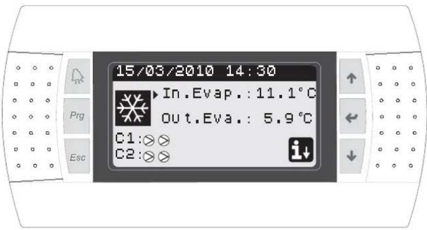
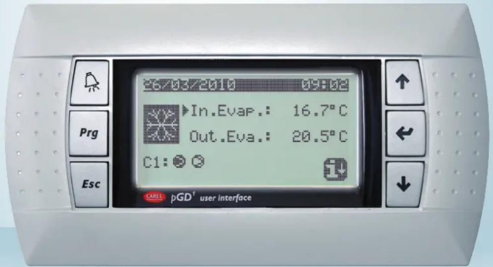
User interface
The unit control panel allows quick setting of the machine functioning parameters and their display. The display is made up from a graphical matrix with 132 x 64 pixel in order to signal the type of functioning, displaying set pa-
rameters and any alarms that have intervened. All default settings and any modifi cations are memorised in the board. With installation of the PGD1 remote panel, it is possible to replicate all functions and settings available from
the machine at a distance. After a power cut, the unit can re-start automatically keeping the original settings.
The user interface is represented by a graphical display with six keys for navigation. The displays are organised via a hierarchy of menus, which can be activated by pressing the navigation keys. The display default of these menus is represented by the main menu. Navigation among the various parameters takes place using the arrow keys positioned on the right side of the panel. These keys are also used to modify the selected parameters.
text_image
15/03/2010 14:30 In.Evap.: 11.1°C out.Eva.: 5.9°C C1:⊗⊗ C2:⊗⊗- INTERFACE COMMAND KEYS: • MAIN MENU ICONS:
| Function Key | Icon Meaning | ||
 | ALARMS keyOne press displays the list of active alarms;One prolonged press (at least 5 seconds) resets the active alarm; | Cooling mode activated | |
| Heating mode activated | |||
 | MENU ACTIVATION keyPressing this key activates navigation among the menus; | ||
| Simultaneous defrosting mode activated | |||
 | MENU EXIT keyPressing this key goes back to the display of the previous menu; | ||
| Separate defrosting mode activated. This mode is only available for twin-circuit models, in which it is possible to proceed with defrosting engaging just one circuit; | |||
 | NAVIGATION key (+)Pressing this key while navigating among the menus/parameters, allows to pass to the next menu/parameter;Pressing this key during modification of a parameter, increases the value of the parameter selected; | ||
 | NAVIGATION key (enter)Pressing this key while navigating among the menus, allows to enter the menu selected;Pressing this key during navigation among parameters, allows to select the parameter displayed and enter the modification mode;Pressing this key during modification of a parameter, confirms the modifications to the value of the parameter selected; | • FIXED icon = Compressor OFF;• FLASHING icon = Compressor in switch-on phase, in standby due to safety times; | |
 | • FIXED icon = Compressor ON;• FLASHING icon = Compressor in switch-off phase, in standby due to safety times; | ||
| Compressor forded off; | |||
 | NAVIGATION key (-)Pressing this key while navigating among the menus/parameters, allows to pass to the previous menu/parameter;Pressing this key during modification of a parameter, decreases the value of the parameter selected; | Limited compressor; | |
| [4XW8] | Compressor in alarm conditions; | ||
| Access to the "quick menu" by pressing the key | |||
Menu structure and navigation
Navigation in the various menus for the management of the NXW units is represented by the layout shown at the side. In this layout find the representation of the various menus, via
which the unit functions are managed, ordered by sequence and highlighting which function keys must be pressed to navigate among the various menus.
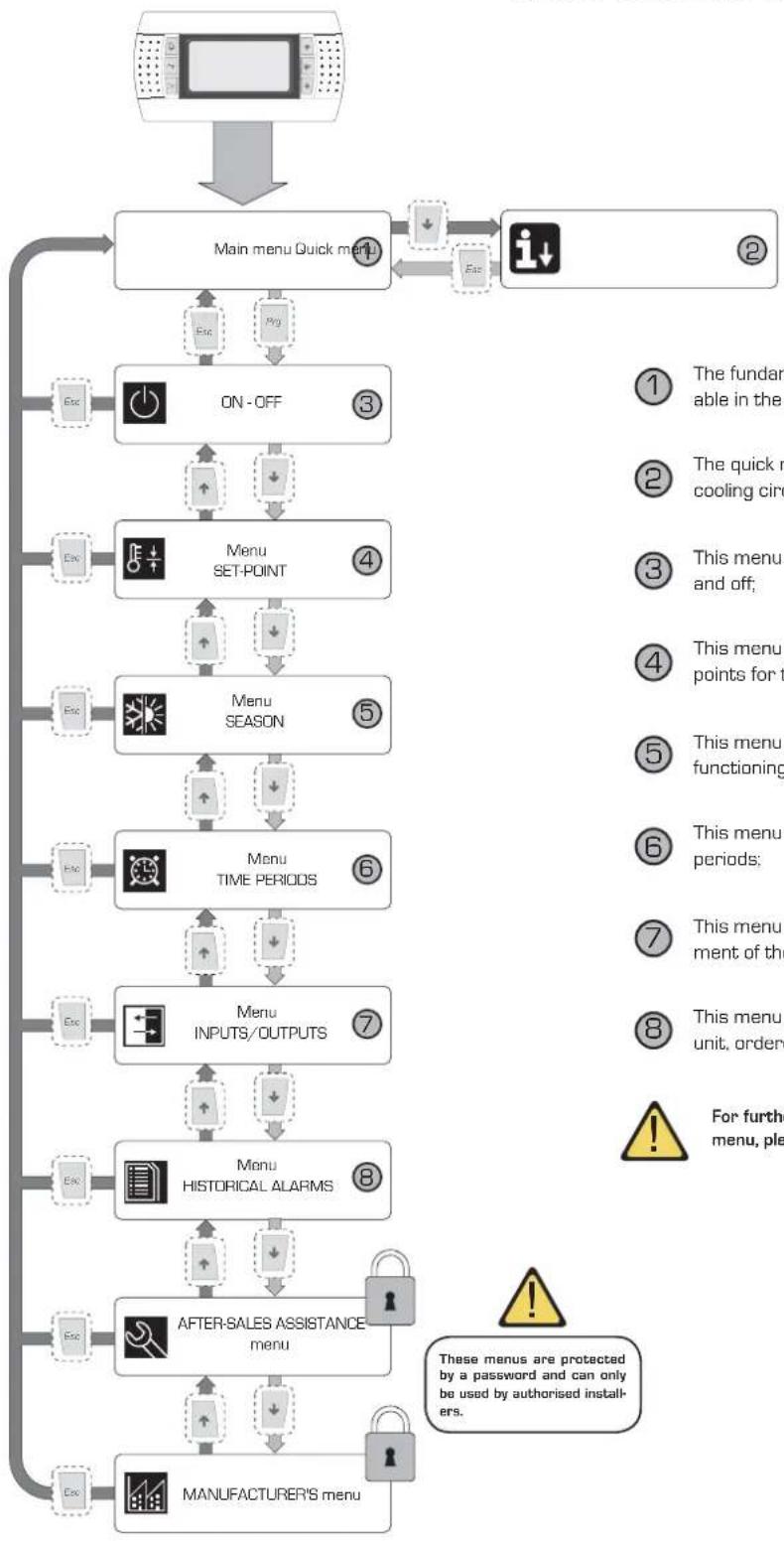
flowchart
Menu management flowchart covering quick menu, ON/OFF, SET-POINT, SEASON, TIME PERIODS, INPUTS/OUTPUTS, and historical alarm handling steps.① The fundamental information regarding use of the unit is available in the main menu;
② The quick menu contains some information regarding the cooling circuit and the unit compressors;
③ This menu contains the commands for switching the unit on and off;
④ This menu contains the parameters for setting the work set points for the various functioning modes of the unit;
⑤ This menu contains the parameters for selecting the various functioning modes of the unit;
⑥ This menu contains the parameters for setting the timer periods;
⑦ This menu contains the parameters linked to the management of the inputs and the outputs piloted by the unit boards;
This menu contains the list of the alarms occurring on the unit, ordered by date;

For further details regarding the parameters contained in every menu, please refer to the relative chapters at every menu.

Use operational procedures
To manage or modify the operational parameters of the NXW units, the control panel interface on the machine must be used. The fundamental operations that the user must be able to perform for correct use of the unit are the following:
(1) Pass from one menu to another;
(2) Select and modify a parameter;
1
Pass from one menu to another
(a) In order to scroll the various menus (the order with which the menus are displayed is represented in the previous page) it is first necessary to enter the menu selection mode by pressing the [^A_0] key;
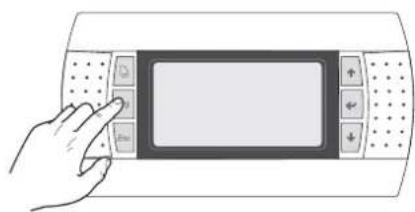
natural_image
Illustration of a hand interacting with a touchscreen device (no text or symbols visible)(b) Once the menu selection mode has been entered, scroll these using the arrow keys: the [+] key to pass to the previous menu and the [+] key to pass to the next menu;
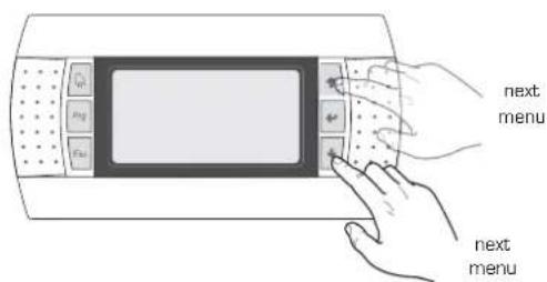
text_image
next menu next menu(c) When the desired menu is displayed, press the [ ] key to enter the menu. To exit the menu and go back to the menu selection mode, press the [ ] key;
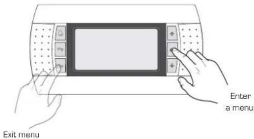
text_image
Enter a menu Exit menu2
Selecting and modifying a parameter
(a) Once the selected menu has been entered (following the procedure 1) it is possible to scroll the windows that make it up using the arrow keys, using the (+) key to pass to the previous parameter and the (+) key to pass to the next parameter;
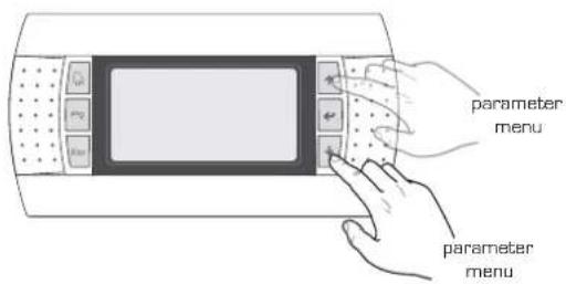
text_image
parameter menu parameter menu(c) When the desired parameter is displayed, press the [•] key to enter the parameter. To exit the parameter and go back to the parameter selection mode, press the [•] key;
ATTENTION:
Once a parameter has been selected, by pressing the [•] key, automatically enter the modification mode of that parameter. From this mode it is possible to set the desired values for the parameters, following the procedure below:
[1] pressing the [•] key, a flashing cursor will appear near to the first field of the parameter that can be modified (if fields that can be modified are not displayed, no cursor will appear);
[2] pressing the (+) key or the (-) key, the value of the field will increase or decrease;
[3] by pressing the (←) key, the modifications to the field value will be confirmed, saving it in the memory;
On the basis of the type of parameter selected, the number of fields that can be modified may vary;
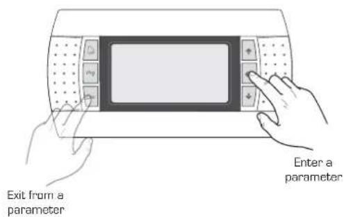
text_image
Exit from a parameter Enter a parameterMAIN menu
| MAIN menu | ||
| Visualisation on unit display Index Display/ | Parameter | |
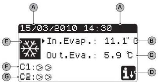 | A Date and time: this data is only displayed in this window (default window on unit switch-on or during normal functioning). | |
| B | Evaporator inlet temperature: displays the temperature of the return water to the system; | |
| C | Evaporator outlet temperature: displays the temperature of the water produced by the machine; | |
| D | QUICK MENU key: icon that represents access to the quick menu [to access this menu, press the ☑ key]; | |
| E Mode: displays the unit functioning mode: ·Cooling mode [ ✉ ]; ·Heating mode [ ✉ ]; ·Simultaneous defrosting mode [ ✉ ]; ·Separate defrosting mode [ ✉ ]; | ||
| F/G | Compressor circuit 1/2 state: the state of the compressors of circuit 1/2 is represented (if the unit envisions two cooling circuits) with an icon (if circuit 1 or 2 is composed of several compressors, an icon is used for every compressor); the icons that can be used are: | |
| FIXED icon = Compressor OFF; FLASHING icon = Compressor in switch-on phase, in stand-by due to safety times; | ||
| FIXED icon = Compressor ON; FLASHING icon = Compressor in switch-off phase, in stand-by due to safety times; | ||
| Compressor forded off; | ||
| Limited compressor; | ||
| Compressor in alarm conditions; | ||

QUICK-MENU parameters
| MAIN MENU - QUICK MENU - Cooling circuit information | ||
| Visualisation on unit display Index Display/Parameter | ||
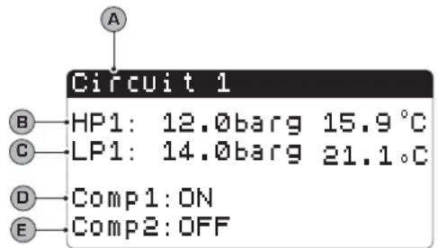 | A | Circuit number: Indicates to which cooling circuit the data displayed refers to. |
| B | High pressure: Indicates the high pressure value measured on the cooling circuit; this data is expressed in (bar) but the corresponding temperature data is also displayed. | |
| C | Low pressure: Indicates the low pressure value measured on the cooling circuit; this data is expressed in (bar) but the corresponding temperature data is also displayed. | |
| D/E Compressor 1/2 state: Indicates the state of the compressor 1 (of the circuit to which it refers), this state can be one of the following:ON = compressor ON;OFF = compressor OFF;OFF alarm = compressor off due to alarm;OFF stand-by 180s = compressor request but cannot switch-on due to safety times;OFF stand-by 180s = compressor request but cannot switch-on due to safety times; | ||
| MAIN MENU - QUICK MENU - General regulation settings | ||
| Visualisation on unit display Index Display/Parameter | ||
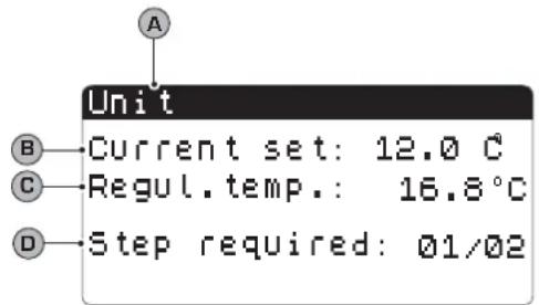 | A | Unit: Indicates the general parameters with which the unit is set. |
| B | Current set point: Indicates the value currently set as work set point. | |
| C Regulation temperature: Indicates the temperature detected by the probe used (this probe can vary on the basis of the type of functioning). | ||
| D | Partialisation steps requested: Indicates how many compressors are on instant by instant. | |

ON/OFF MENU parameters
| ON/OFF menu - Unit switch-on or switch-off from PGD1 panel | |
| Visualisation on unit display Index Display/Parameter | |
[3260]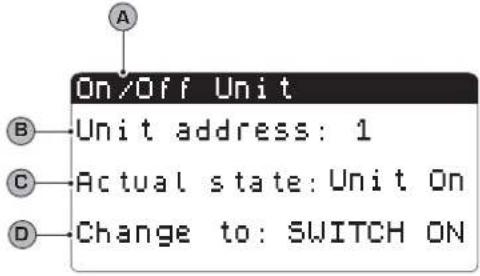 Parameters that can be modified by the user Parameters that can be modified by the user | A Unit On/Off: Indicates the ON/OFF state of the unit. |
| B Board address: logical address of the board. | |
| C State: Indicates the current state of the unit. | |
| D [7/22] Change into: indicates the status in which the unit will be put after the parameter value has been confirmed. Normally the value of this field is in line with that of field (C). To switch-on (if the unit is off) or switch-off (if the unit is on), this field must be modified and the modification confirmed (via the “selection and modification of a parameter” procedure explained in the “Use operational procedure” chapter. | |

SET POINT MENU parameters
| SET POINT menu- Displays the set point currently in use | ||
| Visualisation on unit display Index Display/Parameter | ||
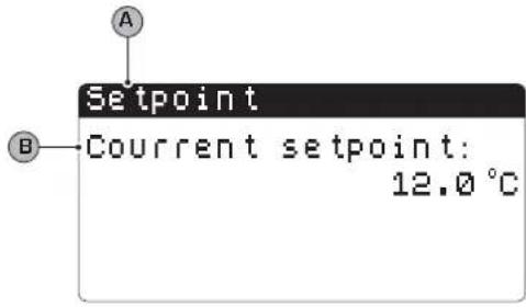 | A Set point: Indicates the work temperature. | |
| B | Current set point: indicates the work set point currently in use on the basis of the envisioned functioning mode. | |
| SET POINT menu - Setting the work set points for COOLING mode | ||
| Visualisation on unit display Index Display/Parameter | ||
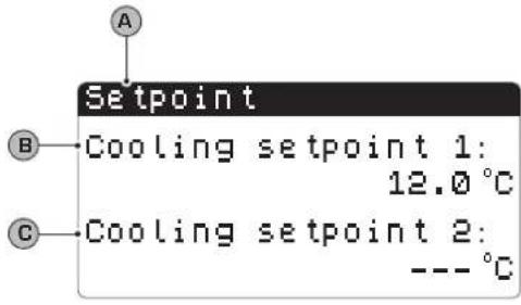 Parameters that can be modified by the user Parameters that can be modified by the user | A Set point: Indicates the work temperature. | |
| B | Cooling set point 1: indicates the temperature set with which to make the unit work when cold. | |
| C Cooling set 2: NOT USED. | ||
 | 2HT] |

COOLING/HEATING menu parameters
| COOLING/HEATING menu - Setting the functioning mode | ||
| Visualisation on unit display Index Display/Parameter | ||
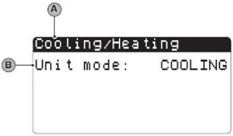 Parameters that can be modified by the user Parameters that can be modified by the user | A Cooling/Heating: Indicates the functioning mode for the unit. | |
B  | Unit Functioning: indicates the unit functioning mode. | |

CLOCK/PERIOD MENU parameters
| CLOCK/PERIOD menu - Setting the system date and time | |
| Visualisation on unit display Index Display/Parameter | |
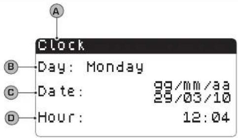 Parameters that can be modified by the user Parameters that can be modified by the user | A Clock: Indicates the date and time of the system |
| B Day: indicates the day of the week (on the basis of system settings). | |
C Date: Indicates today's date. Date: Indicates today's date. | |
D Time: indicates the current time. Time: indicates the current time. | |
| CLOCK/PERIOD menu - Setting the daily time periods | ||
| Visualisation on unit display Index Display/Parameter | ||
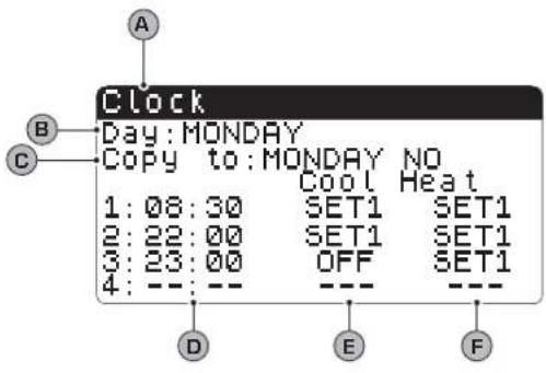 Parameters that can be modified by the user Parameters that can be modified by the user | A Clock: Indicates the date and time of the system | |
B | Day: indicates the day of the week to which the time periods refer, set in the same page. | |
C | Copy to: Indicates the possibility of copying the time period settings of the day selected in the field (B), also for the other days (thus preventing having to repeat the same insertion). This option can be used to copy the settings in a single day (selecting the desired day) or for every day of the week. | |
| D[22CT] | Start time period: indicates the start time of the various time periods (maximum 4 periods daily). It is only specified at the start of the time period as it is considered that the end of a time period coincides with the start of the successive one. | |
E / F | Cooling/Heating: indicates the setting used during the specific time period in the cooling or heating mode. Remember that the time periods specified in this menu are used during the winter season (heating mode) and for the summer (cooling mode), therefore on the basis of the mode active on the unit, appropriate settings will be performed. The possible settings both for cooling and heating are:SET1 = unit on and functioning with set point 1 (the coherent set point will be selected on the basis of the season activated);OFF = the unit is switched off; | |
| CLOCK/PERIOD menu - Setting SPECIAL PERIODS | ||
| Visualisation on unit display Index Display/Parameter | ||
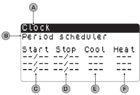 Parameters that can be modified by the user Parameters that can be modified by the user | A Clock: Indicates the date and time of the system | |
| B Special periods: indicates a maximum series of three periods (periods mean at least two days) in which a particular behaviour can be programmed.WARNING: the settings introduced as special periods have priority with respect to normal time periods. | ||
C | Start: Indicates the date of the start of the special period selected (remember that the special period can only be specified within the year in progress, for this reason the date is expressed as a day and month). | |
D | End: indicates the date of the end of the special period selected (remember that the special period can only be specified within the year in progress, for this reason the date is expressed as a day and month). | |
E / F | Cooling/Heating: indicates the setting used during the specific time period in the cooling or heating mode. Remember that the time periods specified in this menu are used during the winter season (heating mode) and for the summer (cooling mode), therefore on the basis of the mode active on the unit, appropriate settings will be performed. The possible settings both for cooling and heating are:SET1 = unit on and functioning with set point 1 (the coherent set point will be selected on the basis of the season activated);OFF = the unit is switched off, | |
| CLOCK/PERIOD menu - Setting SPECIAL DAYS | |
| Visualisation on unit display Index Display/ Parameter | |
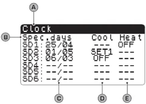 Parameters that can be modified by the user Parameters that can be modified by the user | A Clock: Indicates the date and time of the system |
| B Special days: indicates a series of days when particular behaviour can be programmed.WARNING: the settings introduced as special days have priority with respect to normal time periods and special periods. | |
C  Start: Indicates the special day selected (remember that the special day can only be specified within the year in progress, for this reason the date is expressed as a day and month). Start: Indicates the special day selected (remember that the special day can only be specified within the year in progress, for this reason the date is expressed as a day and month). | |
D/E  Cooling/Heating: indicates the setting used during the specific time period in the cooling or heating mode. Remember that the time periods specified in this menu are used during the winter season (heating mode) and for the summer (cooling mode), therefore on the basis of the mode active on the unit, appropriate settings will be performed. The possible settings both for cooling and heating are:SET1 = unit on and functioning with set point 1 (the coherent set point will be selected on the basis of the season activated);OFF = the unit is switched off, Cooling/Heating: indicates the setting used during the specific time period in the cooling or heating mode. Remember that the time periods specified in this menu are used during the winter season (heating mode) and for the summer (cooling mode), therefore on the basis of the mode active on the unit, appropriate settings will be performed. The possible settings both for cooling and heating are:SET1 = unit on and functioning with set point 1 (the coherent set point will be selected on the basis of the season activated);OFF = the unit is switched off, | |

INPUTS/OUTPUTS MENU parameters
INPUTS/OUTPUTS menu - HIGH/LOW pressure transducers analogue inputs
| Visualisation on unit display Index Display/Parameter | |
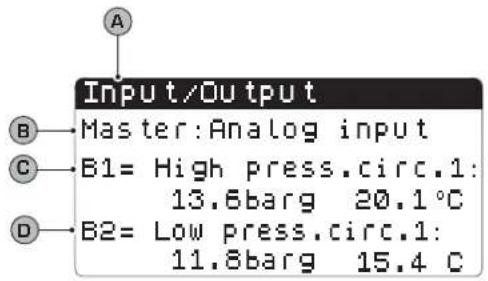 | A Inputs/Outputs: Indicates the state of the different entries/exits. |
| B Master: indicates the type of data displayed; the displays can be:Analogue inputs;Digital inputs;Digital outputs; | |
| C B1: indicates the value read on the high pressure side of the cooling circuit indicated. This reading is expressed as a pressure value and a temperature value. | |
| D B2: indicates the value read on the low pressure side of the cooling circuit indicated. This reading is expressed as a pressure value and a temperature value. | |
INPUTS/OUTPUTS menu - Evaporator IN/OUT temperature analogue inputs
| Visualisation on unit display Index Display/Parameter | |
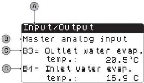 | A Inputs/Outputs: Indicates the state of the different entries/exits. |
| B Master: indicates the type of data displayed; the displays can be:Analogue inputs;Digital inputs;Digital outputs; | |
| C B3: indicates the temperature value of the water in output from the evaporator. | |
| D B2: indicates the temperature value of the water in input to the evaporator. | |
INPUTS/OUTPUTS menu - Condenser OUTPUT temperature analogue inputs
| Visualisation on unit display Index Display/Parameter | |
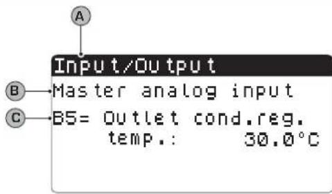 | A Inputs/Outputs: Indicates the state of the different entries/exits. |
| B Master: indicates the type of data displayed; the displays can be:Analogue inputs;Digital inputs;Digital outputs; | |
| C B5: indicates the temperature value of the water in output from the condenser. | |
| INPUTS/OUTPUTS menu - Condenser INPUT temperature analogue inputs | ||
| Visualisation on unit display Index Display/Parameter | ||
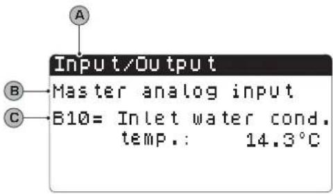 | A Inputs/Outputs: Indicates the state of the different entries/exits. | |
| B | Master: indicates the type of data displayed; the displays can be:Analogue inputs;Digital inputs;Digital outputs; | |
| C B10: indicates the temperature value of the water in input to the condenser. | ||
| INPUTS/OUTPUTS menu - HIGH/LOW pressure pressure switch status digital inputs | |
| Visualisation on unit display Index Display/Parameter | |
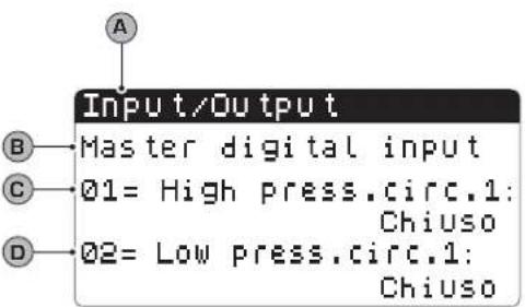 | A Inputs/Outputs: Indicates the state of the different entries/ exits. |
| B Master: indicates the type of data displayed; the displays can be:Analogue inputs;Digital inputs;Digital outputs; | |
| C 01: indicates the status of the high pressure switch, mounted on the cooling circuit indicated. The status of this component can be one of the following:Closed = normal working state;Open = maximum pressure threshold exceeded [HIGH PRESSURE alarm]; | |
| D 02: indicates the status of the low pressure switch, mounted on the cooling circuit indicated. The status of this component can be one of the following:Closed = normal working state;Open = minimum pressure threshold exceeded [LOW PRESSURE alarm]; | |
| INPUTS/OUTPUTS menu - Remote commands digital inputs | |
| Visualisation on unit display Index Display/Parameter | |
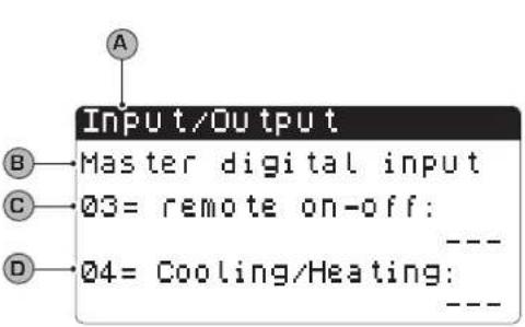 | A Inputs/Outputs: Indicates the state of the different entries/ exits. |
| B Master: indicates the type of data displayed; the displays can be:Analogue inputs;Digital inputs;Digital outputs; | |
| C 03: indicates the status of the digital input with remote ON-OFF function. The status of this input can be one of the following:Closed = unit ON from remote;Open= unit OFF from remote;— = input not used; | |
| D 04: indicates the status of the digital input with remote ON-OFF function. The status of this input can be one of the following:Closed = COOLING mode set from remote;Open = HEATING mode set from remote;— = input not used; | |
| INPUTS/OUTPUTS menu - Compressor magnet circuit breaker flow switch digital inputs | |
| Visualisation on unit display Index Display/Parameter | |
| A Inputs/Outputs: Indicates the state of the different entries/ exits. | |
| B Master: indicates the type of data displayed; the displays can be:Analogue inputs;Digital inputs;Digital outputs; | |
| C 05: indicates the status of the flow switch positioned on the evaporator, the status of this input can be one of the following:Closed = normal functioning;Open = minimum water flow rate threshold exceeded at the evaporator [Flow switch alarm]; | |
| D 06: indicates the status of the compressor magnet circuit breaker indicated, the status of this input can be one of the following:Closed = normal functioning;Open = the compressor load has exceeded the maximum threshold [Compressor magnet circuit breaker alarm]; | |
| INPUTS/OUTPUTS menu - Compressor 2 magnet circuit breaker digital inputs and compressor phases | |
| Visualisation on unit display Index Display/Parameter | |
| A Inputs/Outputs: Indicates the state of the different entries/exits. | |
| B Master: indicates the type of data displayed; the displays can be:Analogue inputs;Digital inputs;Digital outputs; | |
| C 07: indicates the status of the compressor magnet circuit breaker indicated, the status of this input can be one of the following:Closed = normal functioning;Open = the compressor load has exceeded the maximum threshold (Compressor magnet circuit breaker alarm); | |
| D 08: indicates the status of the phase control on the compressors, the status of this input can be one of the following:Closed = normal functioning;Open = incorrect phases detected on the compressor indicated (Serious alarm); | |
 | ||
| INPUTS/OUTPUTS menu - Condenser flow switch digital inputs | ||
| Visualisation on unit display Index Display/Parameter | ||
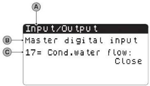 | A Inputs/Outputs: Indicates the state of the different entries/exits. | |
| B | Master: indicates the type of data displayed; the displays can be:Analogue inputs;Digital inputs;Digital outputs; | |
| C 17: | indicates the status of the flow switch positioned on the condenser, the status of this input can be one of the following:Closed = normal functioning;Open = minimum water flow rate threshold exceeded at the condenser (Flow switch alarm); | |
| INPUTS/OUTPUTS menu - Compressors digital outputs | |
| Visualisation on unit display Index Display/Parameter | |
 | A Inputs/Outputs: Indicates the state of the different entries/ exits. |
| B Master: indicates the type of data displayed; the displays can be:Analogue inputs;Digital inputs;Digital outputs; | |
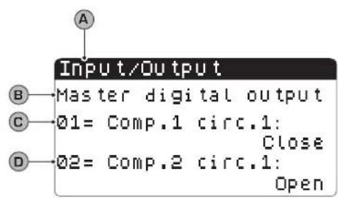
| C/D 01-02: indicates the status of the compressors indicated, the status of these outputs can be one of the following:Closed = compressor ON;Open = compressor OFF; | |
| INPUTS/OUTPUTS menu - Condenser pumps digital outputs | ||
| Visualisation on unit display Index Display/Parameter | ||
 | A Inputs/Outputs: Indicates the state of the different entries/ exits. | |
| B | Master: indicates the type of data displayed; the displays can be:Analogue inputs;Digital inputs;Digital outputs; | |
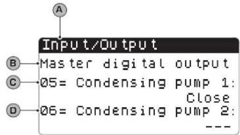
| C/D | 05-06: indicates the status of the pumps indicated, the status of these outputs can be one of the following:Closed = pumps ON;Open = pumps OFF;— = pump not present; | |
INPUTS/OUTPUTS menu - Anti-freeze resistance and compressor phases alarm digital outputs
| Visualisation on unit display Index Display/Parameter | |
 | A Inputs/Outputs: Indicates the state of the different entries/exits. |
| B Master: indicates the type of data displayed; the displays can be:Analogue inputs;Digital inputs;Digital outputs; | |
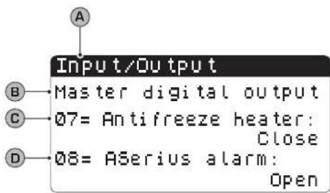
| C 07: indicates the status of the digital output linked to the anti-freeze resistance. The status of this output can be one of the following:Closed = normal functioningOpen = Anti-freeze alarm active; | |
| D 08: indicates the status of the digital output linked to the compressor phases alarm. The status of this output can be one of the following:Closed = compressor phases alarm in progress;Open = no alarm in progress; | |
INPUTS/OUTPUTS menu - Evaporator pump digital outputs
| Visualisation on unit display Index Display/Parameter | |
 | A Inputs/Outputs: Indicates the state of the different entries/ exits. |
| B Master: indicates the type of data displayed; the displays can be:Analogue inputs;Digital inputs;Digital outputs; | |
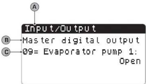
| C 09: indicates the status of the pump indicated, the status of this output can be one of the following:Closed = pump ON;Open = pump OFF; | |
INPUTS/OUTPUTS menu - Solenoid valves digital outputs
| Visualisation on unit display Index Display/Parameter | |
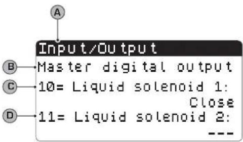 | A Inputs/Outputs: Indicates the state of the different entries/exits. |
| B Master: indicates the type of data displayed; the displays can be:Analogue inputs;Digital inputs;Digital outputs; | |
| C/D 10-11: indicates the status of the solenoid valves indicated, the status of this output can be one of the following:Closed = valve ON;Open =valve OFF;— = valve not present; | |
| INPUTS/OUTPUTS menu - 4-way valves digital outputs | |
| Visualisation on unit display Index Display/Parameter | |
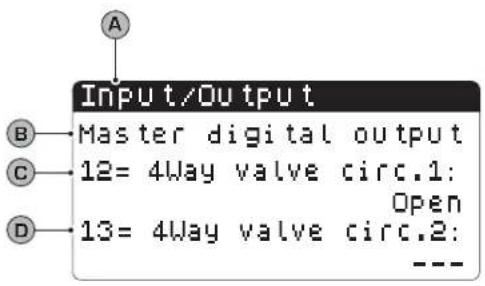 | A Inputs/Outputs: Indicates the state of the different entries/ exits. |
| B Master: indicates the type of data displayed; the displays can be:Analogue inputs;Digital inputs;Digital outputs; | |
| C/D 12-13: indicates the status of the 4-way valves indicated, the status of this output can be one of the following:Closed = valve ON;Open =valve OFF;— = valve not present; | |

Historical ALARMS

The alarms historical menu does not contain user parameters like the menus previously explained, but it is possible to scroll the last 50 alarms that have occurred, ordered by data with some information recorded regarding the status of the machine at the time the alarm was triggered.
Navigate this menu by pressing the ( ) key, as the first display represents the last alarm triggered, while the alarm with index 001 represents the oldest alarm memorised.
| HISTORICAL ALARMS menu - Example of historical alarms | ||
| Visualisation on unit display Index Display | ||
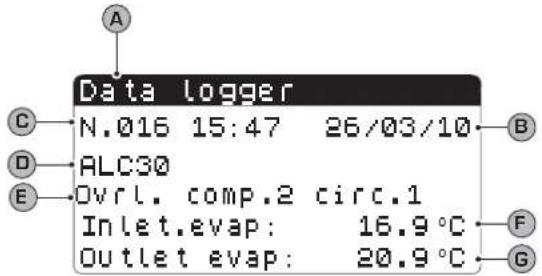 | A Historical alarms: Indicates the alarms recorded in the memory. | |
| B Date: indicates the time and date when the alarm was triggered. | ||
| C | Index: indicates the index with which the alarm is saved in the memory. The lower the index the older the alarm. | |
| D Code: indicates the identification code of the alarm (see alarms table) | ||
| E Description: brief description of the alarm. | ||
| F/G | Input-Output: indicates the evaporator water input and output temperature value at the time the alarm in question was triggered. | |

AFTER-SALES ASSISTANCE menu

The after-sales assistance menu contains some sub-menus that are protected by a password. These sub-menus are not available to the user and their management is only allowed by staff authorised for after-sales assistance of the unit.
| AFTER-SALES ASSISTANCE menu - LANGUAGE CHANGE sub-menu - Language selection | ||
| Visualisation on unit display Index Display | ||
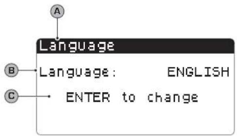 | A Language: Indicates the system language. | |
| B Language: indicates which language is set for the display. | ||
C  | Control: indicates the control for modifying the system language. | |
| [7W26] Parameters that can be modified by the user | ||
| AFTER-SALES ASSISTANCE menu - LANGUAGE CHANGE sub-menu - Enabling of language selection on start-up | ||
| Visualisation on unit display Index Display | ||
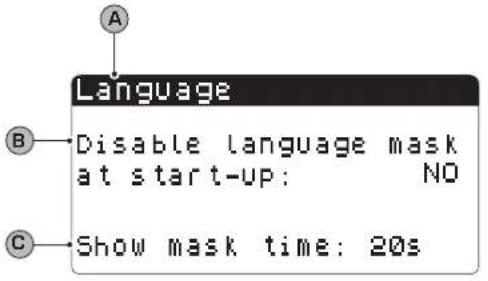 | A Language: Indicates the system language. | |
B  | Control: indicates the possibility to enable or disable the sys-tem language selection at every unit start-up. | |
C  | Display time: indicates the time within which it will be possible to select the system language during the start window. If the language selection window option is disabled on start-up, this parameter will not be visible. | |
| AFTER-SALES ASSISTANCE menu - INFORMATION sub-menu - Display of system information | ||
| Visualisation on unit display Index Display | ||
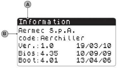 | A Information: Indicates information regarding the system. | |
| B This window indicates some information linked to the control system hardware. | ||
| AFTER-SALES ASSISTANCE menu - BOARD CHANGE sub-menu - Display of board address | ||
| Visualisation on unit display Index Display | ||
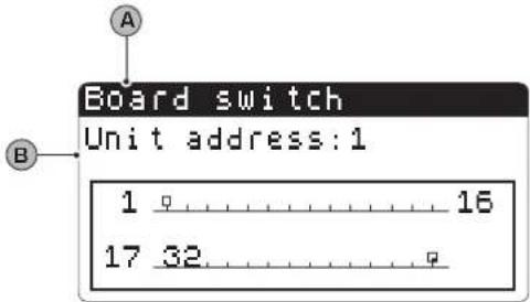 | A Board change: Indicates the address of the board. | |
| B This window indicates the address of the control board. | ||
| AFTER-SALES ASSISTANCE menu - HORS WORKED sub-menu - Display of evaporator pump functioning hours | ||
| Visualisation on unit display Index Display | ||
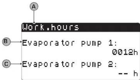 | A Hour counter: Indicates the number of hours of work of the components: | |
| B Evaporator pump 1: indicates how many functioning hours of the pump on the evaporator 1 (if present). | ||
| C Evaporator pump 2: indicates how many functioning hours of the pump on the evaporator 2 (if present). | ||
| AFTER-SALES ASSISTANCE menu - HORS WORKED sub-menu - Display of compressors functioning hours | ||
| Visualisation on unit display Index Display | ||
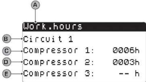 | A Hour counter: Indicates the number of hours of work of the components: | |
| B Circuit 1: Indicates the number of the circuit to which the compressors refer. | ||
| C/D/E | Compressor: indicates how many functioning hours of the compressors present on the unit. | |
| AFTER-SALES ASSISTANCE menu - HORS WORKED sub-menu - Display of condenser pump functioning hours | ||
| Visualisation on unit display Index Display | ||
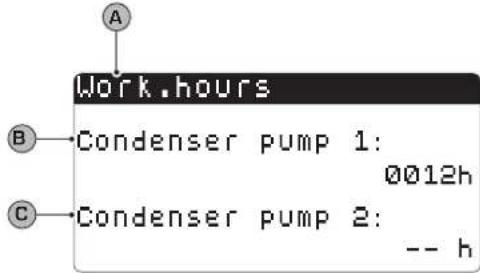 | A Hour counter: Indicates the number of hours of work of the components: | |
| B Condenser 1 pump: indicates how many functioning hours of the pump on the condenser 1 (if present). | ||
| C Condenser 2 pump: indicates how many functioning hours of the pump on the condenser 2 (if present). | ||
Alarms summary table
The units envision the signalling of the possible unit malfunctions. These signals are indicated by the flashing alarm key (bell) on the left part of the display. If the bell is pressed again it allows to display the alarm in progress. The rearm of these alarms can take place automatically, manually or semi-automatically (on the basis of the type and seriousness of the alarm that has occurred). To reset the alarm message, the bell key must be pressed again (remember that resetting the alarm does not solve the cause that generated it, but just the dis-
play is cancelled). The following table lists the possible errors that the unit can generate, and a brief explanation of the possible causes.
Alarms rearm mode:

Manual rearm mode:
The unit is re-started manually by removing and re-applying the voltage.

Automatic rearm mode:
The unit is re-started automatically.

Semi-automatic rearm mode:
The unit is re-started automatically if the alarm repeats a maximum of three times consecutively, after which any new alarm blocks the unit and makes manual rearm necessary.
| ALARMS summary table | ||
| Alarm code Rearm Description | ||
| ALG01 | Clock board broken or not connected | |
| ALG02 | Memory expansion damaged | |
| ALR03 Serious digit out alarm | ||
| AL004 | Slave off-line | |
| ALA05 | Circuit 1 high pressure probe broken or not connected | |
| ALA06 | Circuit 2 high pressure probe broken or not connected | |
| ALA07 | Circuit 3 high pressure probe broken or not connected | |
| ALA08 Circuit 4 high pressure probe broken or not connected | ||
| ALA09 | Circuit 1 low pressure probe broken or not connected | |
| ALA10 Circuit 2 low pressure probe broken or not connected | ||
| ALA11 |  | Circuit 3 low pressure probe broken or not connected |
| ALA12 |  | Circuit 4 low pressure probe broken or not connected |
ALA13 Evaporator  water temperature probe broken or not connected water temperature probe broken or not connected | ||
| ALA14 | [YSKK] | Condenser input water temperature probe broken or not connected |
| ALA15 |  | Evaporator output water temperature probe broken or not connected |
ALA16 Evaporator  water temperature probe 1 broken or not connected water temperature probe 1 broken or not connected | ||
| ALA17 |  | Evaporator output water temperature probe 2 broken or not connected |
ALA18 Evaporator  water temperature probe 3 broken or not connected water temperature probe 3 broken or not connected | ||
| ALA19 |  | Evaporator output water temperature probe 4 broken or not connected |
ALA20 Condenser  water temperature probe 1 broken or not connected water temperature probe 1 broken or not connected | ||
| ALA21 |  | Condenser output water temperature probe 2 broken or not connected |
| ALA22 |  | Condenser output water temperature probe 3 broken or not connected |
ALA23 Condenser  water temperature probe 4 broken or not connected water temperature probe 4 broken or not connected | ||
ALA24 Evaporator  temperature probe broken or not connected temperature probe broken or not connected | ||
| ALA25 |  | External temperature probe broken or not connected |
| ALT26 |  | Compressor 1 - circuit 1 maintenance requested |
ALT26 Compressc  rcuit 1 maintenance requested rcuit 1 maintenance requested | ||
| ALT26 |  | Compressor 3 - circuit 1 maintenance requested |
ALT26 Compressc  rcuit 2 maintenance requested rcuit 2 maintenance requested | ||
| ALT26 |  | Compressor 2 - circuit 2 maintenance requested |
| ALT26 |  | Compressor 3 - circuit 2 maintenance requested |
| ALT26 Compressc [YHSK] rcuit 3 maintenance requested | ||
| ALT26 |  | Compressor 2 - circuit 3 maintenance requested |
ALT26 Compress(  ) circuit 3 maintenance requested ) circuit 3 maintenance requested | ||
| ALT26 |  | Compressor 1 - circuit 4 maintenance requested |
ALT26 Compress(  ) circuit 4 maintenance requested ) circuit 4 maintenance requested | ||
| ALT26 |  | Compressor 3 - circuit 4 maintenance requested |
ALT27 Unit 1 con(  ) fan maintenance request ) fan maintenance request | ||
ALT27 Unit 2 con(  ) fan maintenance request ) fan maintenance request | ||
| ALT28 |  | Condenser 1 pump maintenance request |
ALT28 Condenser (  ) pump maintenance request ) pump maintenance request | ||
| ALT29 |  | Evaporator 1 pump maintenance request |
ALT29 Condenser (  ) pump maintenance request ) pump maintenance request | ||
| ALC30 |  | Compressor 1 circuit 1 magnet-circuit breaker |
ALC30 Compress(  ) circuit 1 magnet-circuit breaker ) circuit 1 magnet-circuit breaker | ||
| ALC30 |  | Compressor 3 circuit 1 magnet-circuit breaker |
| ALC30 |  | Compressor 1 circuit 2 magnet-circuit breaker |
ALC30 Compress(  ) circuit 2 magnet-circuit breaker ) circuit 2 magnet-circuit breaker | ||
| ALC30 |  | Compressor 3 circuit 2 magnet-circuit breaker |
ALC30 Compress(  ) circuit 3 magnet-circuit breaker ) circuit 3 magnet-circuit breaker | ||
| ALC30 | [TDHS] | Compressor 2 circuit 3 magnet-circuit breaker |
ALC30 Compress(  ) circuit 3 magnet-circuit breaker ) circuit 3 magnet-circuit breaker | ||
| ALC30 |  | Compressor 1 circuit 4 magnet-circuit breaker |
ALC30 Compress(  ) circuit 4 magnet-circuit breaker ) circuit 4 magnet-circuit breaker | ||
| Tabella riassuntiva ALLARMI | ||
| Codice allarme Riarmo Descrizione | ||
| ALC30 |  | Magneto termico compressore 3 circuito 4 |
| ALW31 Compress |  uito 1 forzati in OFF per antigelo uito 1 forzati in OFF per antigelo | |
| ALW31 |  | Compressori circuito 2 forzati in OFF per antigelo |
| ALW31 Compress |  uito 3 forzati in OFF per antigelo uito 3 forzati in OFF per antigelo | |
| ALW31 |  | Compressori circuito 4 forzati in OFF per antigelo |
| ALW32 Circuito 1 |  rinamento per tempo massimo rinamento per tempo massimo | |
| ALW32 Circuito 2 |  rinamento per tempo massimo rinamento per tempo massimo | |
| ALW32 |  | Circuito 3 fine sbrinamento per tempo massimo |
| ALW32 Circuito 4 |  rinamento per tempo massimo rinamento per tempo massimo | |
| ALW33 |  | Circuito 1 fine pump-down per tempo massimo |
| ALW33 Circuito 2 |  mp-down per tempo massimo mp-down per tempo massimo | |
| ALW33 |  | Circuito 3 fine pump-down per tempo massimo |
| ALW33 Circuito 4 |  mp-down per tempo massimo mp-down per tempo massimo | |
| ALB34 |  | Bassa pressione da pressostato circuito 1 |
| ALB34 |  | Bassa pressione da pressostato circuito 2 |
| ALB34 Bassa pres |  da pressostato circuito 3 da pressostato circuito 3 | |
| ALB34 |  | Bassa pressione da pressostato circuito 4 |
| ALB35 Bassa pres |  da sonda circuito 1 da sonda circuito 1 | |
| ALB35 |  | Bassa pressione da sonda circuito 2 |
| ALB35 Bassa pres |  da sonda circuito 3 da sonda circuito 3 | |
| ALB35 |  | Bassa pressione da sonda circuito 4 |
| ALB36 Alta pressi |  pressostato circuito 1 pressostato circuito 1 | |
| ALARMS summary table | ||
| Alarm code Rearm Description | ||
| ALB36 |  | Circuit 2 high pressure from pressure switch |
ALB36 Circuit 3 hi  | ssure from pressure switch | |
| ALB36 |  | Circuit 4 high pressure from pressure switch |
| ALB36 High press [wcwc] | m circuit 1 probe | |
| ALB36 |  | High pressure from circuit 2 probe |
ALB36 High press  | m circuit 3 probe | |
ALB36 High press  | m circuit 4 probe | |
| ALP38 |  | Evaporator pump 1 no flow warning |
ALP39 Evaporator  | 2 no flow warning | |
| ALP40 |  | Evaporator pump 1 no flow |
ALP41 Evaporator  | 2 no flow | |
| ALP42 |  | Evaporator pimp 1 magnet circuit breaker |
ALP43 Evaporator  | 2 magnet circuit breaker | |
| ALP44 |  | Condenser pump 1 no flow warning |
| ALP45 |  | Condenser pump 2 no flow warning |
ALP46 Condenser  | 1 no flow | |
| ALP47 |  | Condenser pump 2 no flow |
ALP48 Circuit 1 at  | ze alarm | |
| ALP48 |  | Circuit 2 anti-freeze alarm |
ALP48 Circuit 3 at  | ze alarm | |
| ALP48 |  | Circuit 4 anti-freeze alarm |
ALP49 Circuit 1-2  | zeze alarm | |
| Codice allarme Riarmo Descrizione | ||
| ALP49 |  | Allarme antigelo circuito 3-4 |
ALC50 Allarme an  unità unità | ||
| ALC51 |  | Avviso prevenzione alta pressione circuito 1 |
ALC51 Avviso prev  e bassa pressione circuito 1 e bassa pressione circuito 1 | ||
| ALC51 |  | Avviso prevenzione antigelo circuito 1 |
ALC52 Avviso prev  e alta pressione circuito 2 e alta pressione circuito 2 | ||
ALC52 Avviso prev  e bassa pressione circuito 2 e bassa pressione circuito 2 | ||
| ALC52 |  | Avviso prevenzione antigelo circuito 2 |
ALC53 Avviso prev  e alta pressione circuito 3 e alta pressione circuito 3 | ||
| ALC53 |  | Avviso prevenzione bassa pressione circuito 3 |
ALC53 Avviso prev  e antigelo circuito 3 e antigelo circuito 3 | ||
| ALC54 |  | Avviso prevenzione alta pressione circuito 4 |
ALC54 Avviso prev  e bassa pressione circuito 4 e bassa pressione circuito 4 | ||
| ALC54 |  | Avviso prevenzione antigelo circuito 4 |
| ALC55 |  | Avviso prevenzione antigelo circuiti 1-2 |
ALC55 Avviso prev  e antigelo circuiti 3-4 e antigelo circuiti 3-4 | ||
| ALC56 |  | Avviso prevenzione antigelo unità |
AL57 Allarme pCO  e e | ||
| AL58 |  | Allarme sonda 1 pCOe guasta |
AL59 Allarme son  COe guasta COe guasta | ||
| AL60 |  | Allarme sonda 3 pCOe guasta |
AL61 Allarme son  COe guasta COe guasta | ||
| Alarm code Rearm Description | ||
| AL62 |  | I/O mismatch alarm |
| AL63 |  | Condenser pump 1 magnet circuit breaker alarm |
| AL64 |  | Condenser pump 2 magnet circuit breaker alarm |
text_image
26/06/2010 95:02 In.Evar.: 16.7°C Out.Eva.: 20.5°C C1: © © esc pGD¹ user interfacenatural_image
Illustration of a hand interacting with a touchscreen device (no text or symbols visible)natural_image
Illustration of a hand interacting with a touchscreen device (no text or symbols visible)natural_image
Illustration of a hand interacting with a touchscreen device (no text or symbols visible)Technical data shown in this booklet are not binding.
Aermec S.p.A. shall have the right to introduce at any time whatever modifications deemed necessary to the improvement of the product.