
GZIA 4110HPX - Car radio Ground Zero - Free user manual and instructions
Find the device manual for free GZIA 4110HPX Ground Zero in PDF.
| Product Type | 4-Channel Car Audio Amplifier |
| Brand | Ground Zero |
| Model | GZIA 4110HPX |
| Dimensions (L x W x H) | 280 x 255 x 50 mm |
| Weight | Approx. 2.5 kg |
| Power Supply | 12 V DC (car battery) with fuse, MOS-FET PWM power supply |
| RMS Power @ 2 Ω (1% THD) | 4 x 110 W |
| RMS Power @ 4 Ω (1% THD) | 4 x 70 W |
| RMS Power Bridged @ 4 Ω (10% THD) | 2 x 250 W |
| Frequency Response | 10 Hz – 30 kHz |
| Signal-to-Noise Ratio | 80 dB |
| Adjustable Low-Pass/High-Pass Filter | Yes, 40 – 3000 Hz (low-pass) / 30 – 250 Hz (high-pass) |
| Bass Boost | 0 / +6 / +12 dB at 60 Hz |
| Input Sensitivity (RCA and High Level) | 0.2 – 6 V |
| Input Impedance | Not specified (typical 10 kΩ) |
| Minimum Load Impedance | 2 Ω stereo, 4 Ω bridged |
| Built-in Protections | Overheat, short circuit, overvoltage |
| Input Connectors | RCA (low level), high level (via speaker wires) |
| Output Connectors | Screw terminals for speakers |
| Turn-On Function | Via REMOTE wire (remote control) |
| Enclosure Material | Aluminum (heat sink) |
Frequently Asked Questions - GZIA 4110HPX Ground Zero
User questions about GZIA 4110HPX Ground Zero
0 question about this device. Answer the ones you know or ask your own.
Ask a new question about this device
Download the instructions for your Car radio in PDF format for free! Find your manual GZIA 4110HPX - Ground Zero and take your electronic device back in hand. On this page are published all the documents necessary for the use of your device. GZIA 4110HPX by Ground Zero.
USER MANUAL GZIA 4110HPX Ground Zero
Limited warranty - defective products must be returned in original packaging - please add a copy of the original purchasing invoice showing the purchasing date and a detailed description of the failure. Failure caused by overload, misuse or by using the product for competition purpose are not covered by the warranty.
www.ground-zero-audio.com
We reserve the right to make needed change or improvement to the product without informing customer about this in advance.
Please read before Installation
Thank you for selecting a GROUND ZERO amplifier. We are providing a helpful hints list which should keep you from experiencing unnecessary shut down. Have fun with your Iridium amplifier.
Features
• 2 Ohm Stable (Stereo)
• Variable High- and Lowpass
- Ni-plated connectors
- MOSFET power supply
- Low Level input
- Thermal protection
- Short circuit protection
- Remote Turn-on/Turn-off circuit
• Protection condition LED indicator
• Power on LED Indicator
- High Level input
Introduction
Amplifiers provide high-performance sound reinforcement for your mobile audio equipment.
It's versatility enables compatibility with optional Equalizer, Frequency Dividing Network
Crossovers and other audio processors in a customized system. The Multi-Mode bridging
capabilities allow flexibility in hosting several different speaker configurations.
To achieve optimum performance, it is highly recommend that you read this Owners manual
before the installation.
Tools and materials you need
- Screwdriver
• Electric drill, 3mm - Mounting screws
• Power wire min. 20mm²
• Ground wire min 20mm² - Speaker wire min. 2 × 1.5 ~mm^2
Attention
- As a precaution it is advisable to disconnect the vehicle's battery before making connection to the +12 Volts supply wiring (see owner's manual of your car for further information!)
- Do not drill holes into the tank, the brake pipe, wires or other important parts of the vehicle.
- Never pass wires over sharp angles. It is recommended to buffer the power supply of the amplifier with an capacitor min. 1 Farad.
WARNING
High powered audio systems in a vehicle are capable of generating „Live Concert" high levels of sound pressure, Continued exposure to excessively high volume sound levels may cause hearing loss or damage. Also, operation of a motor vehicle while listening to audio equipment at high volume levels may impair your ability to hear external sound such as; horns, warning signals, or emergency vehicles, thus constituting to a potential traffic hazard. In the interest of safety, Consumer Electronics recommends listening at lower volume levels while driving.
Planning your system
Before beginning the installation, consider the following:
a. If you plan to expand your system by adding other components sometime in the future, ensure an equate space is left, and cooling requirements are met.
b. If your radio/source is equipped with Pre-Amp outputs, it is recommended to utilize them to drive the amplifier.
c. Are your components matched? The peak power rating of your speakers must be greater than the Amplifiers. They also must be 2-8 Ohms impedance (This information is normally printed on the speaker magnet.)
d. Consider both the length of your leads, and routing when choosing the mounting location. Pre-Amp input jacks require a length of high quality shielded male to male RCA patch cord.
Mounting your amplifier
a) Select a suitable location that is convenient for mounting, accessible for wiring and has enough room for air circulation and cooling.
b) Use the amplifier as a template to mark the mounting holes, remove the amplifier and drill 4 holes, use extreme caution, inspect underneath surface before drilling.
Warning
Investigate the layout of you automobile thoroughly before drilling or cutting any holes. Take care when you work near the thanks, lines, or hydraulic lines, and electrical wiring. Don't mount this system so that wire connections are unprotected or are subject to pinching or damage from nearby objects.
The +12 Volt DC power wire must be fused at the battery positive terminal connection. Before making or breaking power connections at this system power terminals, disconnect the +12 Volt wire at the battery end.
Confirm your radio / cassette player and / or other equip, mount is turned off while connecting the input jacks and speaker terminals.
If you need to replace the power fuse, replace it only with a fuse identical to that supplied with the system. Using a fuse of different type or rating may result in damage to this system which isn't covered by the warranty.
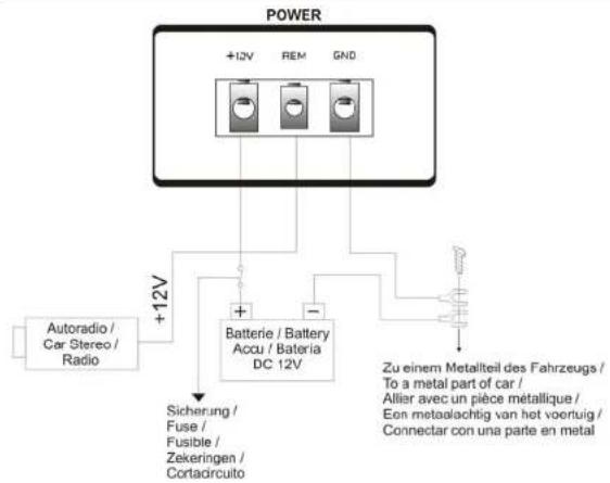
Power connection
flowchart
graph TD
    A["POWER"] --> B["+12V"]
    A --> C["Batterie / Battery Accu / Bateria DC 12V"]
    B --> D["Autoradio / Car Stereo / Radio"]
    C --> E["Sicherung / Fuse / Fusible / Zekeringen / Cortadircuito"]
    C --> F["-"]
    C --> G["+"]
    G --> H["Zu einem Metalteil des Fahrzeugs / To a metal part of car / Allier avec un pièce metallique / Een metaalachtig van het voortuig / Connectar con una parte en metal"]
Wiring connection
Attention! - min. 20mm^2 wires are necessary for power connection!
(1) Ground: Ground connection should be passed directly to the car body as short as possible (max. 1m)
(2) +12 Volt: Power connection should be passed directly to the battery. Please pay attention on a correct fuse protection of the installation with an Inline device with a max. wire length to the battery of 30 cm.
(3) Remote turn on: This connection is getting connected with the remote control line of the radio. It is used for turning on and off the amplifier.
High Input
If your head unit is not equipped with a Cinch output for driving an amplifier, you can connect the speaker outputs directly to the high input of the amplifier. It is rarely possible (depending on the used car stereo) that this operation mode leads to interferences. To avoid or clear them, you should connect the GND cable of the high input directly to the ground connection (GND) of the power terminal.
Connections
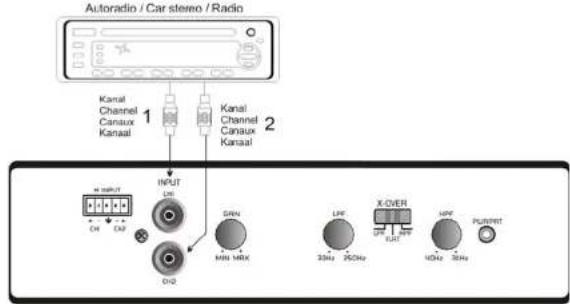
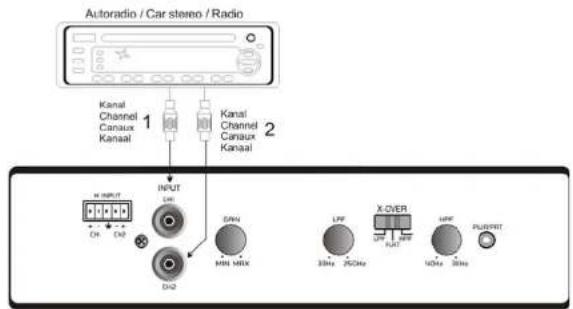
GZIA 2075HPX / 2125 HPX / 2230 HPX
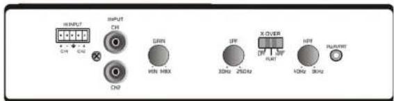
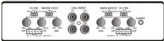
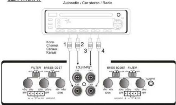
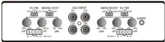
GZIA 4110HPX
Connections
GZIA 2075HPX / 2125 HPX / 2230 HPX
GZIA 4110HPX
flowchart
graph TD
    A["Autoradio / Car stereo / Radio"] --> B["Filter"]
    B --> C["BASSI DOST"]
    C --> D["LOW INPUT"]
    D --> E["BASSI DOST"]
    E --> F["Filter"]
    F --> G["RUNVRET"]

    subgraph Filter
        H1["90Hz 30Hz"]
        H2["80Hz 200Hz"]
        H3["50Hz 1MHz"]
        H4["GRB"]
    end

    subgraph Output
        I1["10Hz 30Hz"]
        I2["30Hz 200Hz"]
        I3["100Hz 1MHz"]
        I4["GRB"]
    end

    subgraph Control
        J1["10Hz 30Hz"]
        J2["30Hz 200Hz"]
        J3["100Hz 1MHz"]
        J4["GRB"]
    end

    K["Kanal Channel Canaux Kanal"] --> L["1"]
    K --> M["2"]
    K --> N["3"]
    K --> O["4"]
Low Level input:
These are driven by the line output of your in dash radio or intermediate signal processor. Separate left and right signals can be applied for stereo or mono operation but both inputs must be driven with the same signal for proper bridged operation. If only mono signal is available, a Y-adapter is required.
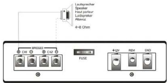
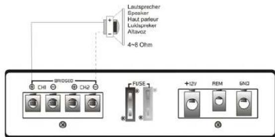
Speaker connection
GZIA 2075HPX / 2125 HPX / 2230 HPX
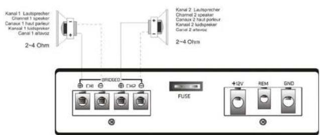
Bridged wiring
GZIA 2075HPX / 2125 HPX / 2230 HPX
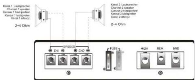
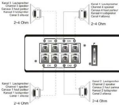
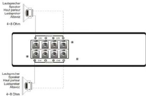
Speaker connection
GZIA 4110HPX
Bridged wiring
Adjusting the audio level
For the best performance, you must set LEVEL (MIN'MAX) on the side of the amplifier to adjust the level of the audio signals.
- Use a screwdriver to turn LEVEL(MIN/MAX) fully to MIN
- Turn the auto sound system's volume control to about two-third of its full range.
- Adjust LEVEL(MIN/MAX) to a comfortable listening level
- Turn up the auto sound system's volume control until the sound begins to distort.
Then immediately turn the volume down to a point just before where the distortion began.
Caution: Never turn up the auto sound system's volume control more than needed to adjust the audio level, more than two thirds of its maximum volume. - Adjust LEVEL (MIN/MAX) until the sound is at the maximum level you want the amplifier two produce.
- Adjust the auto sound system's volume control to a comfortable listening level.
Trouble shooting
This power amplifier has protection features to prevent any damages from misuse or faulty conditions. If the unit some excessive heat, short circulated speakers or overload, the protection indicators will light, and the system will be turned off. In order to check the occurred problem, you should turn all levels down and all power off and carefully check the installation for wiring mistakes or short. If the amplifier shuts down due to excessive heat, the protection indicators will not light; simply allow time for the unit to cool.
Before removing your amplifier, refer to the list below and follow the suggested procedures. Always test the speakers and their wires first.
| Problem Check points | |
| Amplifier is not powered up | Check that there is battery power on the +12V terminal.Check that remote terminal has at least +12V DC remote connection.Check a good ground connection. Check all fuses.Check the protection LED is not in. |
| Protection LED illuminates when amplifier is powered up | Check shorts on speaker wires.Remove speaker wires and reset the amplifier. If the protection LED still comes on, then the amplifier is faulty. |
| Fuse blowing | Check that the minimum speaker impedance is correct.Check short on power cable and vehicle chassis. |
| Overheating | Check that the minimum speaker impedance is correct.Check speaker shorts.Check that there is a good airflow around the amplifier. |
| Sound too low / Distorted sound | Check that the input level control is set to match the output level of the unit.Check the head unit volume.Check speaker shorts.Check that crossover frequencies have been properly set. |
| High hiss / engine noise in speakers | Check a good ground and for speaker shorts.Disconnect all RCA inputs from the amplifier. If hiss'noise disappears, check it with a good RCA interconnect. Then check the component driving the amplifier. |
Specifications
| Model | GZIA2075HPX | GZIA2125HPX | GZIA2230HPX | GZIA4110HPX |
| RMS power @ 2 Ω,1% THDCEA Standard CEA-2006-A | 2 x 75 W 2 x | 125 W 2 x 230 W | 4 x 110 W | |
| RMS power @ 4 Ω,1% THDCEA Standard CEA-2006-A | 2 x 60 W 2 x | 80 W 2 x 150 W | 4 x 70 W | |
| RMS power @ 4Ω Bridged14,4 V, 10% THD | 1 x 200 W 1 | x 300 W 1 x 540 W | W 2 x 250 W | |
| Damping factor | >70 >70 | >70 >70 | ||
| Signal to noise ratio | 80 dB 80 dB | 80 dB 80 dB | ||
| X-over crossover | 40 - 3000 Hz /30 - 250 Hz | 40 - 3000 Hz /30 - 250 Hz | 40 - 3000 Hz /30 - 250 Hz | 40 - 3000 Hz /30 - 250 Hz |
| Bass boost | - | - | - | 0 / +6 / +12dB |
| Bass boost Frequency | - | - | - | 60 |
| Frequency response | 10 Hz - 30 kHz | 10 Hz - 30 kHz | 10 Hz - 30 kHz | 10 Hz - 30 kHz |
| Input sensitivity | 0,2 - 6 V | 0,2 - 6 V | 0,2 - 6 V | 0,2 - 6 V |
| Channel separation | 60 dB 60 dB | 60 dB 60 dB | ||
| THD | < 0.08 | < 0.08 | < 0.1 | < 0.8 |
| DimensionsW x H x L mm | 170 x 255 x 50 | 200 x 255 x 50 | 260 x 255 x 50 | 280 x 255 x 50 |
| DimensionsW x H x L inch | 6.60" x10.04" x 1.97" | 7.87" x10.04" x 1.97" | 10.24" x10.04" x 1.97" | 11.02" x10.04" x 1.97" |
Limited warranty - defective products must be returned in original packaging - please add a copy of the original purchasing invoice showing the purchasing date and a detailed description of the failure. Failure caused by overload, misuse or by using the product for competition purpose are not covered by the warranty.
www.ground-zero-audio.com
We reserve the right to make needed change or improvement to the product without informing customer about this in advance.
GZIA 4110HPX
Connexion RCA
GZIA 2075HPX / 2125 HPX / 2230 HPX
GZIA 4110HPX
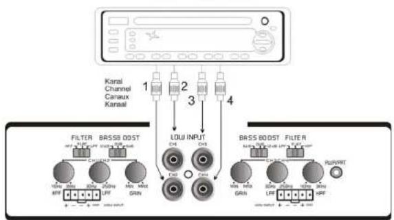
flowchart
graph TD
    A["Antenna"] --> B["Kanal Channel Canaux Kanali"]
    B --> C["Filter"]
    B --> D["BASS 0OST"]
    B --> E["LOW INPUT"]
    B --> F["BASS BOOST FILTER"]
    C --> G["1"]
    D --> H["2"]
    E --> I["3"]
    F --> J["4"]
Limited warranty - defective products must be returned in original packaging - please add a copy of the original purchasing invoice showing the purchasing date and a detailed description of the failure. Failure caused by overload, misuse or by using the product for competition purpose are not covered by the warranty.
www.ground-zero-audio.com
We reserve the right to make needed change or improvement to the product without informing customer about this in advance.
Limited warranty - defective products must be returned in original packaging - please add a copy of the original purchasing invoice showing the purchasing date and a detailed description of the failure. Failure caused by overload, misuse or by using the product for competition purpose are not covered by the warranty.
www.ground-zero-audio.com
We reserve the right to make needed change or improvement to the product without informing customer about this in advance.


- Please read before Installation
- Features
- Introduction
- Tools and materials you need
- Attention
- WARNING
- Planning your system
- Before beginning the installation, consider the following:
- Mounting your amplifier
- Attention! - min. 20mm2 wires are necessary for power connection!
- High Input
- Low Level input:
- Adjusting the audio level
- Trouble shooting
- Specifications
- Connexion RCA
Brand : Ground Zero
Model : GZIA 4110HPX
Category : Car radio