
GZPA 1.6500SPL - Car stereo Ground Zero - Free user manual and instructions
Find the device manual for free GZPA 1.6500SPL Ground Zero in PDF.
| Brand | Ground Zero |
| Model | GZPA 1.6500SPL |
| Product type | Mono Class D amplifier |
| Max power @ 1 Ω (10% THD) | 1 x 6500 W |
| Max power @ 1 Ω (1% THD) | 1 x 5800 W |
| Max power @ 2 Ω (1% THD) | 1 x 3400 W |
| Max power @ 4 Ω (1% THD) | 1 x 1800 W |
| Max power @ 1 Ω 18 V (10% THD) | 1 x 8000 W |
| Efficiency | >86% |
| Damping factor (100 Hz @ 4 Ω) | >170 |
| Signal-to-noise ratio | >65 dB |
| Low-pass filter | 35 Hz ~ 250 Hz (adjustable) |
| Subsonic filter | 10 Hz ~ 70 Hz (adjustable) |
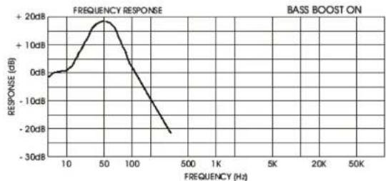
| Bass boost | 0 ~ +9 dB (adjustable 30 Hz ~ 90 Hz) |
| Phase shift | 0 ~ 180° (adjustable) |
| Input sensitivity | 200 mV ~ 10 V |
| Supply voltage | 12 V (max 18 V) |
| Dimensions (W x H x D) | 625 x 75 x 300 mm |
| Chassis material | Aluminum |
| Built-in protection | LED Power and Protect, overheat and short-circuit protection |
| Inputs/outputs | RCA line input and output, remote input (REMOTE) |
| Link function | Yes (Master/Slave) |
| Stable impedance | 1 Ω (2 Ω in linked mode) |
| Maintenance | Clean with a soft dry cloth. Disconnect the battery before any intervention. |
| Warranty | According to legal rights. Return in original packaging with receipt. |
Frequently Asked Questions - GZPA 1.6500SPL Ground Zero
User questions about GZPA 1.6500SPL Ground Zero
0 question about this device. Answer the ones you know or ask your own.
Ask a new question about this device
Download the instructions for your Car stereo in PDF format for free! Find your manual GZPA 1.6500SPL - Ground Zero and take your electronic device back in hand. On this page are published all the documents necessary for the use of your device. GZPA 1.6500SPL by Ground Zero.
USER MANUAL GZPA 1.6500SPL Ground Zero
Limited warranty - defective products must be returned in original packaging - please add a copy of the original purchasing invoice showing the purchasing date and a detailed description of the failure. Failure caused by overload, misuse or by using the product for competition purpose are not covered by the warranty.
wwwground-zero-audio.com
We reserve the right to make needed change or improvement to the product without informing customer about this in advance.
Thank you for selecting a GrouNo Zero Plutonium amplifier. We are providing a helpful hints list
which should keep you from experiencing unnecessary shut down
Introduction Class-D Amplifier
Amplifiers provide high-performance sound reinforcement for you mobile audio equipment. It's versatility enables
compatibility with optional equalizer, frequency dividing network crossovers, and other audio processors in a
customized system.
The Multi-Mode bridging capabilities allow flexibility in hosting several different speaker configurations.
To achieve optimum performance, it is highly recommend that you read this owners manual before beginning the
Features
Class-P High Power App
Efficiency>86%
Damping factor >170 (GZPA 1.6500SPL), >250 (GZPA 1.10000SPL) at 4Ω
Unable with 1g
12 stable (CHT) 1000
Dual HosFet PWM Power Supplies
Power and Produc
Lowpass cros967
- Subscript filter
1BO-Phase Shift Variable
Aluminium heat sin
RCAINPUT/OUTPUT
Bassrromote contro
+9dbBassboost
- Operating voltage: DC 10V ~ 18V input
2x0 Gauge / Summ battery Input Connectors
Tools and materials you need
Screwdriver, electric drill 1/8 carbide drill bit
LSC PAWSPWNSWRS (min-59.0m2)
Ground your amplifier ons motor close to installation location
Use 12 AWG speaker wite or header from your amplifier to your speakers
Lock for burs in the path of your wires and file the flat to avoid puncture.
Use 16 AWG wire for remote trigger
Note all wire gauges are based on stranded wire with polarity indicators on two wire configurations.
Caution!
- Please use great caution drilling your trunk, your gas tank and brake lines can be damaged by puncturing with your drillbit - this could cause damage or failure of your cars operating systems.
- As a precaution it is advisable to disconnect the vehicle's battery before making connection to the +12 Volts supply wiring (see owner's manual of your car for further information).
- 0 AWG / min. 50mm^2 (blicker if planning for additional amplifiers) wire is recommended both the power and grounds. Both types are available at most mobile audio dealers or installation shops.
WARNING
High powered audio systems in a vehicle are capable of generating "Live Concert" high level of sound pressure. Continued exposure to excessively high volume sound levels may cause hearing loss or damage. Also, operation of a motor vehicle while listening to audio equipment at high volume levels may impair your ability to hear external sound such as; horns, warning signals, or emergency vehicles, thus constituting to a potential traffic hazard. For safety reasons we recommends listening at lower volume levels while driving.
Planning your system
a) select a suitable location that is convenient for mounting, is accessible for writing and has enough room for air circulation and cooling.
b) If your radio is equipped with preamplifier outputs (RCA), it is advisable to use them.
Mounting your amplifier
- Select a suitable location that is convenient for mounting, is accessible for wiring and has smol room for air circulation and cooling.
- Use the amplifier a template to mark the mounting holes, remote the amplifier and drill 4 holes (use extreme caution, inspect underneath surface before drilling!)
- Secure the amplifier using the screws provided
Connections
Connections
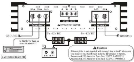
1.) GROUND: To vehicle Chassis
To avoid ignition noise caused by ground loops, it is necessary that the amplifiers be grounded to a clean, bare metal surface of the vehicles chassis.
NOTE: GROUND WIRE SHOLD NOT BE EXTENDED MORE THAN 3 FT.(1 Meter) min. 0 AWG/50mm²
2.) +12 Volt (Fused) Constant power: To Battery (+)
Due to the power requirements of the amplifier, this connection should be made directly to the positive (+) terminal of battery. For safely reasons, install an in-line fuse holder (not included) as close to the battery positive (+) terminal as possible with a rating not exceeding value of fuses in amp.
3.) Remote Turn-On Input: to power antenna output of Car Stereo
This amplifier is turned "ON" remotely when the vehicle's stereo is turned "ON".
Turning on your amplifier
The amplifier automatically turns on a few seconds after you turn your vehicle's ignitions switch to ACC ON or turn on your auto sound system, depending on how you wired the system. The POWER LED on the side of the amplifier lights when the amplifier is on.
Important: Your amplifier requires 30 amps or more of power from your vehicle's battery during operation. To protect your battery from discharging, do not operate the amplifier unless your vehicle is running.
Note: Your amplifier temporarily shuts down if it gets too hot, then restarts automatically once it cools down.
For the best performance, you must set LEVEL (MIN/MAX) on the side of the amplifier to adjust the level of the audio signals.
- Use a screwdriver to turn LEVEL(MIN/MAX) fully to MIN
- Turn the auto sound system's volume control to about two-third of its full range.
- Adjust LEVEL(MIN/MAX) to a comfortable listening level
- Turn up the auto sound system's volume control until the sound begins to distort. Then immediately turn the volume down to a point just before where the distortion began. Caution: Never turn up the auto sound system's volume control more than needed to adjust the audio level, more than two thirds of its maximum volume.
- Adjust LEVEL (MIN/MAX) until the sound is at the maximum level you want the amplifier two produce.
- Adjust the auto sound system's volume control to a comfortable listening level.
Turning on your amplifier
RCA Connections
■Single Rmp Input Connection
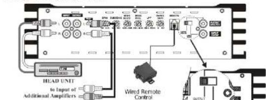
If no sound, please check MASTERSLAVE switch. The mode switch should be in "OUTPUT MASTER" position. (If in "INPUT SLAVE" position, no sound will come out)
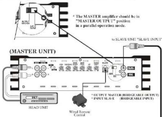
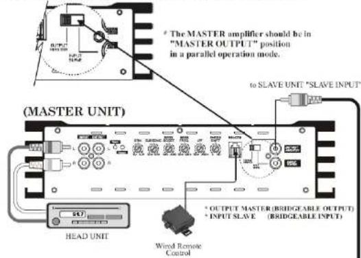
RCA Connections
Dual Amp Input Connection (MASTER & SLAVE RCR Connection)
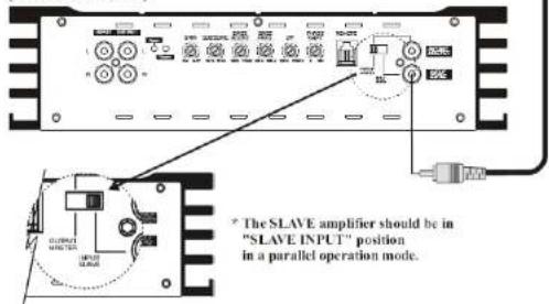
(SLAVE UNIT)
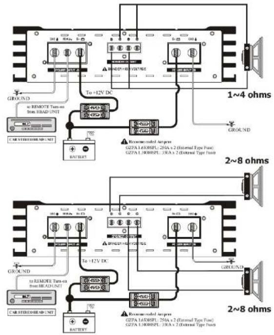
Single amp power & speaker connection
Dual amp power & speaker connection - Linkmode
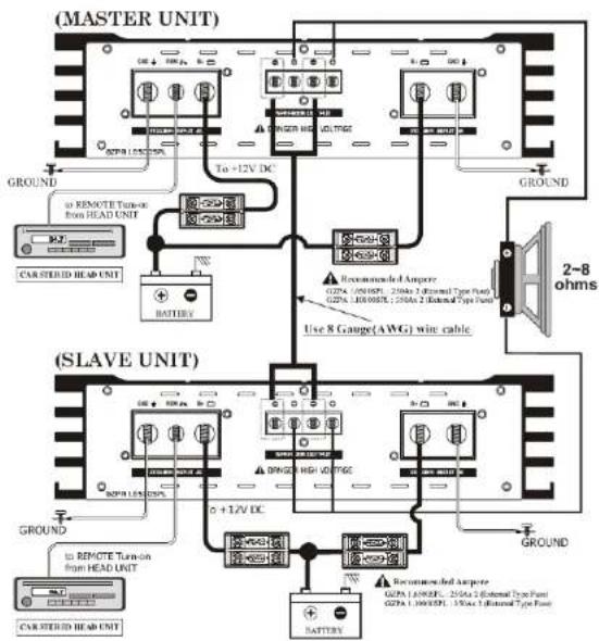
Using a dual amplifier configuration, the MASTER amplifier has total control over the SLAVE amplifier. For the linkmode we recommend NOT to use an external link-module.
Caution!
When utilizing the dual amplifier configuration it is important to note that the connected speaker load can be no lower than 2 ohms. Connecting a lower impedance load can damage the amplifier and void your warranty.
Trouble shooting
This power amplifier has protection features to prevent any damages from misuse or faulty conditions. If the unit senses excessive heat, short circuited speakers or overload, the protection indicators will light, and the system will be turned off. In order to check the occurred problem, you should turn all levels down and all power off and carefully check the installation for wiring mistakes or short. If the amplifier shuts down due to excessive heat, the protection indicators will not light: simply allow time for the unit to cool. Before removing your amplifier, refer to the list below and follow the suggested procedures. Always test the speakers and their wires first.
| Problem Check points | |
| Amplifier is not powered up | · Check that there is battery power on the +12V terminal. · Check that remote terminal has at least +12V DC remote connection. · Check a good ground connection. Check all fuses. · Check the protection LED is not lit. |
| Protection LED illuminates when amplifier is powered up | · Check shorts on speaker wires. · Remove speaker wires and reset the amplifier. If the protection LED still comes on, then the amplifier is faulty. |
| Fuse blowing | · Check that the minimum speaker impedance is correct. · Check short on power cable and vehicle chassis. |
| Overheating | · Check that the minimum speaker impedance is correct. · Check speaker shorts. · Check that there is a good airflow around the amplifier. |
| Sound too low / Distorted sound | · Check that the input level control is set to match the output level of the unit. · Check the head unit volume. · Check speaker shorts. · Check that crossover frequencies have been properly set. |
| High hiss / engine noise in speakers | · Check a good ground and for speaker shorts. · Disconnect all RCA Inputs from the amplifier. If hiss/noise disappears, check it with a good RCA Interconnect. Then check the component driving the amplifier. |
Specifications
| Model GZPA 1.6500SPL GZPA | 1.10000SPL | |
| RMS power @ 1 Ω, 10% THD CEA Standard CEA-2006-A | 1 x 6500W 1 x 9500W | |
| RMS power @ 1 Ω, 1% THD CEA Standard CEA-2006-A | 1 x 5800W 1 x 8300W | |
| RMS power @ 2 Ω, 1% THD CEA Standard CEA-2006-A | 1 x 3400W 1 x 4800W | |
| RMS power @ 4 Ω, 1% THD CEA Standard CEA-2006-A | 1 x 1800W 1 x 2600W | |
| RMS power @ 1 Ω 18 V, 10% THD | 1 x 8000W 1 x 11000W | |
| RMS power @ 2 Ω Linkmode 14,6 V, 1% THD | 1 x 11000 W 1 x 15000W | |
| Damping factor | >170 (100Hz @ 4 Ω) | >250 (100Hz @ 4 Ω) |
| Signal to noise ratio >65 dB >65 dB | ||
| Lowpass crossover 35Hz ~ 250Hz | 35Hz ~ 250Hz | |
| Subsonic Filter | 10Hz ~ 70Hz | 10Hz ~ 70Hz |
| Bass boost | 0 ~ +9dB | 0 ~ +9dB |
| Bass boost Frequency | 30Hz ~ 90Hz | 30Hz ~ 90Hz |
| Phase shift | 0 ~ 180° | 0 ~ 180° |
| Frequency range | 10 Hz ~ 250 Hz (+/-1dB) | 10 Hz ~ 250 Hz (+/-1dB) |
| Efficiency @ 4 Ω | 86% | 86% |
| Input sensitivity | 200mV to 10V (+/- 5%) | 200mV bis 10V (+/- 5%) |
| Dimensions W x H x L mm | 625 x 75 x 300 mm | 870 x 75 x 300 mm |
| Dimensions W x H x L inch | 24.61" x 2.95" x 11.81" | 34.25" x 2.95" x 11.81" |
Limited warranty - defective products must be returned in original packaging - please add a copy of the original purchasing invoice showing the purchasing date and a detailed description of the failure. Failure caused by overload, misuse or by using the product for competition purpose are not covered by the warranty.
wwwground-zero-audio.com
We reserve the right to make needed change or improvement to the product without informing customer about this in advance.
Dual Rmp Input Connection (MASTER & SLRVE RCR Connection)
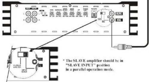
(SLAVE UNIT)
Limited warranty - defective products must be returned in original packaging - please add a copy of the original purchasing invoice showing the purchasing date and a detailed description of the failure. Failure caused by overload, misuse or by using the product for competition purpose are not covered by the warranty.
wwwground-zero-audio.com
We reserve the right to make needed change or improvement to the product without informing customer about this in advance.
