LAR100B - Car stereo TOKAI - Free user manual and instructions
Find the device manual for free LAR100B TOKAI in PDF.

User questions about LAR100B TOKAI
0 question about this device. Answer the ones you know or ask your own.
Ask a new question about this device
Download the instructions for your Car stereo in PDF format for free! Find your manual LAR100B - TOKAI and take your electronic device back in hand. On this page are published all the documents necessary for the use of your device. LAR100B by TOKAI.
USER MANUAL LAR100B TOKAI
1 MANUEL D'UTILISATION
13 USER MANUAL
text_image
102.0 MHZ FM1 Tokai Bluetooth® 4x45nm LED F1 102003Lire attentivement la notice avant d'utiliser l'appareil Before operating this product, please read user manual completely
1. AVANT DE COMMENCER
CHER CLIENT
text_image
Dashboard ① ② ③ ④ ⑤ ⑥ ⑦ ⑧ ⑨Façade détachable
natural_image
Line drawing of a computer drive with an arrow indicating left-hand movement (no text or symbols)text_image
Diagram showing file processing steps: adding two components (A and B) into a computer case, then adding one to an open case.Notes:
flowchart
graph LR
    A["1: Receipts"] --> B["2: Display"]
    B --> C["3: Hand press"]
    C --> D["4: Screen with scroll"]
    D --> E["5: Display with buttons"]
    E --> F["6: Display with buttons"]
natural_image
Sequence of four steps showing a mechanical assembly or folding process, with no visible text or symbols.NETTOYAGE DES CONNECTEURS
natural_image
Black electronic device with a cable and display screen, no visible text or symbols on the device itself.flowchart
graph LR
    A["Insert from device"] --> B["Insert from rack"]
    B --> C["View from rack to server or control panel"]
text_image
Symbol of a trash bin crossed out by a diagonal line, indicating no waste or dischargeSelecting fine audio equipment such as the unit you have just purchased is only the start of your musical enjoyment. Now it is time to consider how you can maximize the fun and excitement your equipment offers. We want you to get the most out of your equipment by playing it at a safe level. One that lets the sound come through loud and clear without annoying blaring or distortion - and, most importantly, without affecting your sensitive hearing.
Sound can be deceiving. Over time your hearing “comfort level” adapts to higher volumes of sound. So what sounds «normal» can actually be loud and harmful to your hearing.
Guard against this by setting your equipment at a safe level BEFORE your hearing adapts.
To establish a safe level:
- Start your volume control at a low setting
- Slowly increase the sound until you can hear it comfortably and clearly, and without distortion we want you listening for a lifetime.
Once you have established a comfortable sound level:
- Set the dial and leave it there.
Take a minute to do this now; it will help to prevent hearing damage or loss in the future. After all, we want you listening for a lifetime.
ABOUT THIS MANUAL
This product features a number of sophisticated functions ensuring superior reception and operation. All are designed for the easiest possible use, but many are not self-explanatory.
This operation manual is intended to help you benefit fully from their potential and to maximize your listening enjoyment.
We recommend that you familiarize yourself with the functions and their operation by reading through the manual before you begin using this product. It is especially important that you read and observe the “precaution” as follows.
In this operation manual, the Basic Operation for each sound source is outlined at the beginning of its explanation, covering simple operation for that source, such as merely playing music.
PRECAUTION
- Read through this instruction manual before installation and use.
- Do not touch the power plug with wet hand.
- Switch off the main power when the unit is not in use. (Disconnect the power plug from the power outlet when you do not intend to use the unit for a prolonged period of time.)
- Do not open the cover or touch any of the components exposed out of the unit, only for qualified technicians.
- Do not expose the unit under direct sunlight or nearby objects that radiate heat to avoid damage to the unit.
- Do not place the unit in moist and humid conditions, which affect the pick-up of the unit.
- Clear the panel and case with soft dry cloth only, do not apply any kind of thinner, alcohol or sprays.
2. WIRE CONNECTION
text_image
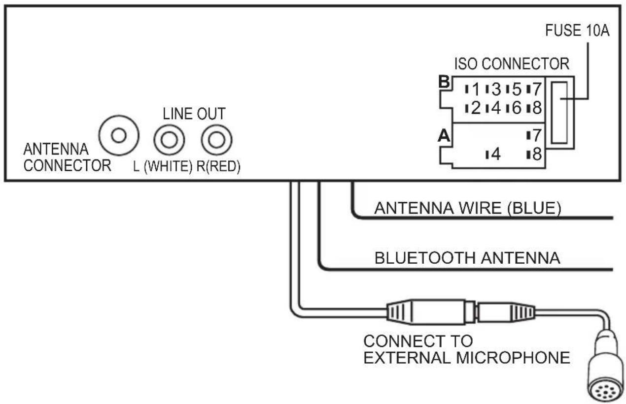
FUSE 10A ISO CONNECTOR B 1 3 5 7 2 4 6 8 A 7 14 8 ANTENNA WIRE (BLUE) BLUETOOTH ANTENNA CONNECT TO EXTERNAL MICROPHONEWIRE CONNECTION
LINE OUT:
RED (RIGHT) WHITE (LEFT)
ANTENNA WIRE: BLUE
CONNECTOR A
-
MEMORY +12V
-
+12V (TO IGNITION KEY)
-
GROUND
Note: (connector A no. 7) must be connected by car ignition key in order to avoid that car battery being drained when the car will be not used for long period.
CONNECTOR B
- REAR RIGHT SPEAKER (+)
- REAR RIGHT SPEAKER (-)
- FRONT RIGHT SPEAKER (+)
- FRONT RIGHT SPEAKER (-)
- FRONT LEFT SPEAKER (+)
- FRONT LEFT SPEAKER (-)
- REAR LEFT SPEAKER (+)
- REAR LEFT SPEAKER (-)
Note: If your car does not have ISO connector, you can procure it from any car accessory shop
2. WIRE CONNECTION & INSTALLATION
INSTALLATION
PRECAUTIONS
- Choose the mounting location carefully so that the unit will not interfere with the normal driving functions of the driver.
- Avoid installing the unit where it would be subject to high temperatures, such as from direct sunlight or hot air from the heater, or where it would be subject to dust, dirt or excessive vibration.
- Use only the supplied mounting hardware for a safe and secure installation.
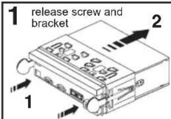
- Be sure to remove the front panel before installing the unit.
NOTE: Inclination angle for car radio installation must not exceed 30^ otherwise the front panel will not open.
text_image
1 release screw and bracket 2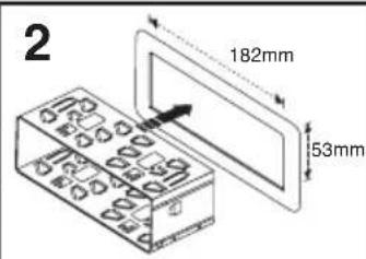
text_image
2 182mm 53mm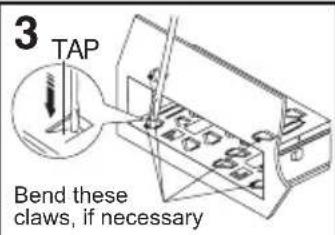
text_image
3 TAP Bend these claws, if necessary
natural_image
Diagram of a device with two rectangular blocks and a connecting rod, no visible text or symbolsNote: Keep the release key in a safe place as you may need it in future to remove the unit from the car.
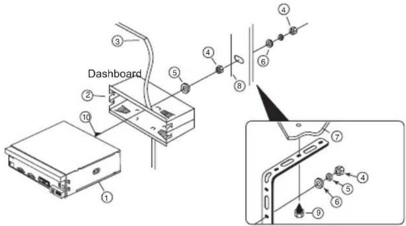
TO SUPPORT THE UNIT
- UNIT
- RELEASE CASE
- DASH BOARD
- HEX NUT
- LOCK WASHER
- PLAIN WASHER
- CAR BODY
- REAR SUPPORT STRAP
- TAPPING SCREW
- M5 X 15 HEX BOLT
text_image
Dashboard 1 2 3 4 5 6 7 8 9 ① ② ③ ④ ⑤ ⑥ ⑦ ⑧Detaching and attaching the front panel
The front panel of this unit can be detached in order to prevent the unit from being stolen.
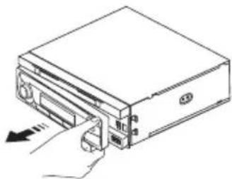
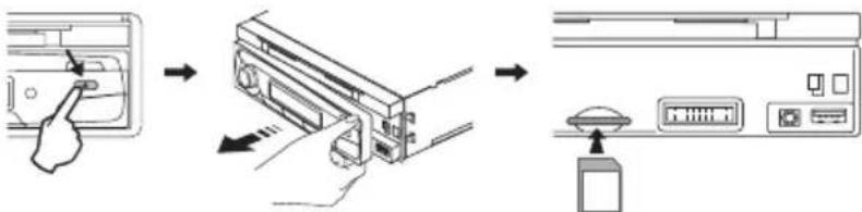
DETACHING THE FRONT PANEL
Before detaching the front panel, be sure to press the button to OFF first. Then press the button and detach the panel by pulling it towards you as illustrated.
Note: Be sure not to drop the panel when detaching it from the unit.
natural_image
Line drawing of a computer drive with an arrow indicating left-hand motion (no text or symbols)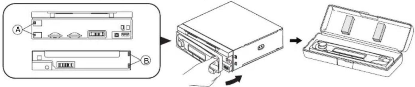
text_image
Diagram showing file processing steps: adding two components (A and B) into a CD drive, then adding a final box.Notes:
- Make sure that the front panel is in the right way up when attaching it to the unit as it cannot be attached upside down.
- Do not press the front panel hard against the unit when attaching it. It can be easily attached by pressing it lightly against the unit.
- When you carry the front panel with you, put it in the supplied front panel case.
- Do not press hard or give excessive pressure to the display window of the front panel when attaching it to the unit.
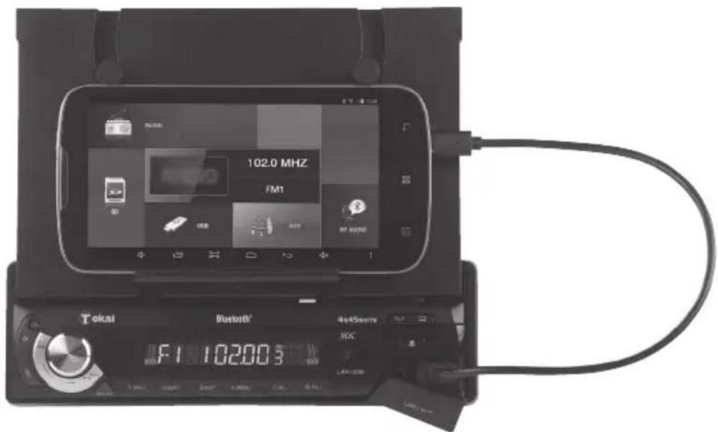
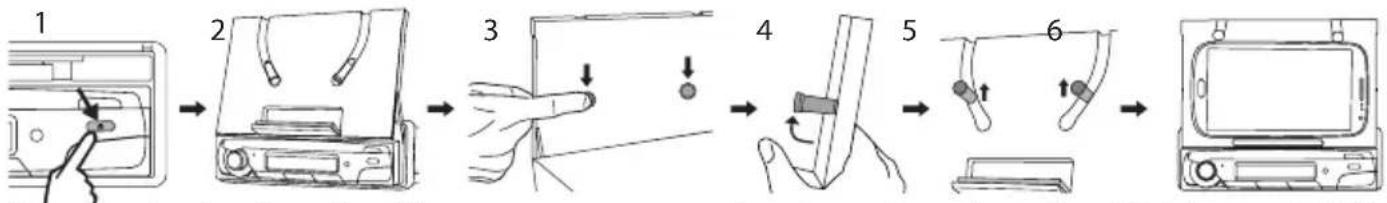
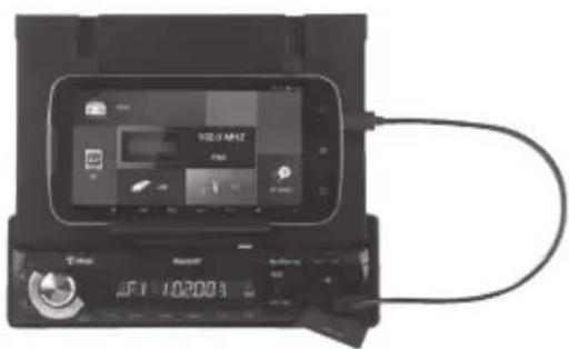
FIXING THE SMARTPHONE & TABLET ON THE MOUNT
- To slide the retractable motorized mount for Smartphone/ tablet press
- Press the 2 rear buttons to lift up the 2 holding arms for Smartphone/tablet.
- You will notice that they are adjustable upwards depending on the size of you Smartphone or tablet.
- Thanks to the stand and the holding arms you can comfortably fix you Smartphone or tablet against the mount for an optimum support.
- To put back the retractable motorized mount, fold down the holding arms and press the button ☐
flowchart
graph LR
    A["1: Receipts"] --> B["2: Display"]
    B --> C["3: Touch"]
    C --> D["4: Screen with Adjustment"]
    D --> E["5: Display with Rejection"]
    E --> F["6: Display with Rejection"]
Important note: The adjustable mount can accommodate Smartphone from 4" and Tablet up to 7.85".
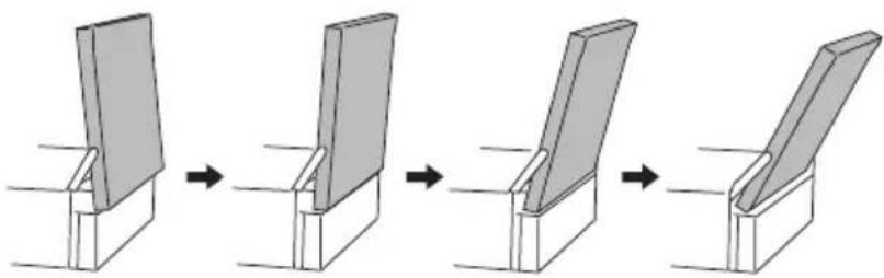
UPPER DISPLAY PANEL TILT ANGLE
Press TILT button repeatedly to choose the desired tilt angle.
natural_image
Sequence of four steps showing a mechanical assembly or folding process, with no visible text or symbols.CLEANING THE CONNECTOR
The unit may not function properly if the connectors between the unit and the front panel are contaminated with dirt. In order to prevent this from happening,
detach the front panel by pressing the button and clean the connector from time to time.
Clean the connector with a cotton swab together with contact cleaner as illustrated. Be sure to clean them carefully pin by pin and make sure not to damage the connecting points.
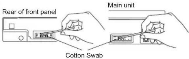
text_image
Rear of front panel Main unit Cotton Swab3. LOCATION OF PARTS AND CONTROLS
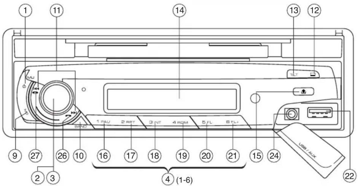
text_image
1 11 14 13 12 TU MU BAND 1 PAU 2 RPT 3 INT 4 ROM 5 FL 6 FL+ USB / AUX 9 27 26 10 16 17 18 19 20 21 15 24 2 3 4 (1-6) 22- POWER ON/OFF ( ) ☑MUTE (MU)
- FUNCTION SELECT BUTTON: CONTROLS FOR BASS/TREBLE/BALANCE/FADER / CALL LIST / DISPLAY / INITIAL VOLUME / ADJ / TA VOL / EON / AF / TA / PTY / DSP / TA SEEK / PI SOUND / RETUNE / MASK DPI
- VOL UP/VOL DOWN BUTTON: CONTROLS FOR BASS/TREBLE/BALANCE/FADER /
CALL LIST / DISPLAY / INITIAL VOLUME / ADJ / TA VOL / EON / AF / TA / PTY / DSP / TA SEEK / PI SOUND / RETUNE / MASK DPI
- PRESET STATIONS (1,2,3,4,5,6)
- 'AF' FUNCTION (ALTERNATIVE FREQUENCIES)
- 'TA' FUNCTION (TRAFFIC ANNOUNCEMENT)
- 'PTY' FUNCTION (PROGRAM TYPE)
- EQUALIZER (DSP)
- MODE/LOUDNESS BUTTON (MD)
- BAND/ENTER BUTTON (BAND)
- AUTOMATIC OR MANUAL TUNING (FREQ UP OR ▶REQ DOWN /TRACK ▶SEARCH BUTTON)
- OPEN/CLOSE UPPER PANEL DISPLAY FOR HOLD MOBILE PHONE / TABLET ( )
- UPPER PANEL DISPLAY TILT ANGLE (TILT)
- LCD DISPLAY
- PANEL RELEASE BUTTON ( )
- PAUSE BUTTON
- REPEAT BUTTON
- INTRO BUTTON (Preview all Tracks)
- RANDOM BUTTON
20, 21. PREVIOUS/NEXT FOLDER (MP3/WMA Files only) - USB PORT
- SD CARD SLOT
- FRONT AUX IN
- PHONE NUMBER
- ANSWER A CALL
- END A CALL ( )
- RESET BUTTON
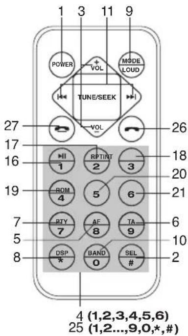
text_image
1 3 11 9 POWER + VOL MODE LOAD TUNE/SEEK 27 VOL 26 17 16 HI RPTINT 18 1 2 3 20 19 ROM 5 6 21 4 PTY AF TA 6 7 7 8 9 10 5 DSP BAND SEL 2 8 * 0 # 2 4 (1,2,3,4,5,6) 25 (1,2...,9,0,*,#)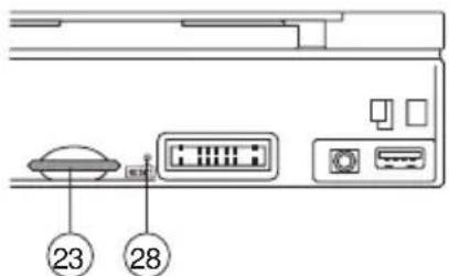
text_image
23 28Press and hold this key to switch the unit on and off. Also this unit can be turned on by pressing any key. If you just press this key briefly, it will turn to MUTE. To return to sound, press it briefly again.
2. SELECT
3. VOLUME UP/DOWN
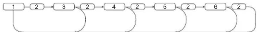
Turning the VOL knob Right or Left (3), you can adjust VOL/BASS/TREB/BAL/FAD. To select other functions, press the "VOL" knob shortly until the desired functions is shown on the display. Figure 1 shows how control functions are selected using the "VOL" knob.
flowchart
graph LR
    A["1"] --> B["2"]
    B --> C["3"]
    C --> D["2"]
    D --> E["4"]
    E --> F["2"]
    F --> G["5"]
    G --> H["2"]
    H --> I["6"]
    I --> J["2"]
    J --> K["End"]
Fig. 1 Selection of sound control functions
-
VOL
-
SEL
-
BAS
-
TRE
-
BAL
-
FAD
Turning the VOL knob Right or Left. Increase or decrease the volume by turning used to adjust the BASS, TREBLE, BALANCE and FADER.

or VOL. These buttons can be

flowchart
graph LR
    A["2 sec."] --> B["SEL"]
    B --> C["CALL LIST"]
    C --> D["SEL"]
    D --> E["DISP"]
    E --> F["SEL"]
    F --> G["IN VOL"]
    G --> H["SEL"]
    H --> I["ADJ"]
    I --> J["SEL"]
    J --> K["TA VOL"]
    K --> L["SEL"]
    L --> M["EON ON"]
    M --> N["SEL"]
    N --> O["AF ON"]
    O --> P["ASK DPI"]
    P --> Q["SEL"]
    Q --> R["RETUNE L"]
    R --> S["SEL"]
    S --> T["PI MUTE"]
    T --> U["SEL"]
    U --> V["TA ALARM"]
    V --> W["SEL"]
    W --> X["DSP NONE"]
    X --> Y["SEL"]
    Y --> Z["PTY OFF"]
    Z --> AA["SEL"]
    AA --> AB["TA OFF"]
    AB --> AC["SEL"]
Press and hold VOL knob to adjust CALL LIST/DISPLAY/INITIAL VOLUME/ADJUST TIME/TA VOLUME/EON/ALTERNATIVE FREQUENCIES/TRAFFIC ANNOUNCEMENT/PROGRAM TYPE/DSP SOUND/TA ALARM/PI MUTE/RETUNE/MASK DPI
CALL LIST (see page 7)
DISPLAY
Display informations such as radio frequencies, clock, track and other informations depending on the playing MODE.
IN VOL
Turn VOL knob to adjust Initial Volume level using this mode.
ADJ
Can adjust clock time. Turn VOL knob clockwise to set hours and counter clockwise to set minutes.
TA VOL
Turn VOL knob to adjust TA Volume (The volume level when Traffic announcement is transmitted).
EON
Turn VOL knob to select EON condition, ON or OFF.
USING THE RDS FUNCTION
What is RDS?
The RDS (Radio Data System) is a digital information system developed by the EBU (European Broadcast Union).
Piggy-backed on normal FM broadcasts, RDS offers a variety of information services and automatic retuning functions for RDS-compatible car stereos.
'AF/REG' function (ALTERNATIVE FREQUENCIES)
When AF/REG mode is selected, the radio checks the signal strength of the AF all the time.
- Regional mode ON:
AF switching or PI SEEK is implemented to the station which have all PI codes same as current station. REG segment is turned on, in LCD display.
- Regional mode OFF
The regional code in the format of PI code is ignored when AF switching or PI SEEK is implemented.
'TA' function (TRAFFIC ANNOUNCEMENT)
When pressed momentarily, it is activated as TA mode on or off
When TA mode is on and traffic announcement is transmitted
- When the unit is operating other than FM-RDS mode such as USB, SD or AUX etc, it will switch to FM-RDS mode temporarily.
- If the volume level was under the threshold point, it will be raised to the threshold point.
- When TP station is received, TP segment is turned on in LCD display.
'PTY' function (PROGRAM TYPE)
You can select PTY mode by turning Volume knob as below.
PTY OFF/NEWS/AFFAIRS/INFO/SPORT/EDUCATE/DRAMA/CULTURE/SCIENCE/VARIED/POP M/ROCK M/EASY M/LIGHT M/CLASSICS/OTHER M/WEATHER/FINANCE/CHILDREN/SOCIAL/RELIGION/PHONE IN/TRAVEL/LEISURE/JAZZ/COUNTRY/NATION M/OLDIES/FOLK M/DOCUMENT
DSP
Turn VOL knob to select DSP mode (Classic, POP, Rock, Flat)
TA ALARM/SEEK
TA SEEK mode:
When newly turned station does not receive TP information for 5 sec., the radio retunes to next station which has not the same station (PI) as the last station, but has the TP information. In TA seek mode, the current station can be changed to the completely different station because the unit searches TP station when the field strength of the current station is very weak, or the current station has no TP signal.
TA ALARM mode:
Any automatic retune mode is not activated, just can hear Beep sound.
PI MUTE/SOUND
Action when 2 stations with different programme identification (PI) codes are on the same frequency: SOUND: The radio switches to the new channel for a few seconds and then switches back again MUTE: The radio is muted
RETUNE L/S
RETUNE L: Select 90 seconds as the initial time of automatic TA search.
RETUNE S: Select 30 seconds as initial time.
MASK DPI/ALL
MASK DPI: masked only the AF which has different PI.
MASK ALL: masked the AF which has different PI and NO RDS signal with field strength.
4. PRESET STATIONS (1,2,3,4,5,6)
Six numbered preset buttons store and recall stations for each band.
Storing a station:
- Select a band (if needed)
- Select a station
- Hold a preset button longer than one second. Preset station number appears in the display when station is saved.
Recall a station:
- Select band (if needed)
- Press a preset button for less than one second to select stored station.
Note: This unit is equipped with built-in memory I.C. (Integrated Circuits) to save user settings such as tuner preset stations and audio control settings. To cancel these settings, switch to Radio mode, press and hold button "1" for 2 seconds (do not release button) followed by pressing MD button. Unit will automatically restart after 5 seconds.
5. 'AF/REG' function (ALTERNATIVE FREQUENCIES)
Operation: See the SËL button of the 'AF/REG' function (ALTERNATIVE FREQUENCIES) section.
6. 'TA' function (TRAFFIC ANNOUNCEMENT)
Operation: See the SEL button of the 'TA' function (TRAFFIC ANNOUNCEMENT) section
7. 'PTY' function (PROGRAM TYPE)
Operation: See the SEL button of the 'PTY' function (PROGRAM TYPE) section
8. EQUALIZER (DSP)
Press DSP to select between (Classic, Rock, POP, Flat) equalizer modes.
9. MODE/LOUDNESS BUTTON (MD)
By pressing this key, user can select. AUX/TUNER/USB/SD/A2DP mode. LOUDNESS: By pressing this key longer than 2 sec., you can select LOUDNESS mode.
10. BAND BUTTON (BD)
Each band is toggled cyclically by pressing this key FM1---FM2---FM3---MW(AM)1---MW(AM)2.
11. AUTOMATIC OR MANUAL TUNING (FREQ UP ▶FREQ DOWN) (A) RADIO MODE
When pressed momentarily, these keys are operated as SEEK tuning mode. When pressed longer than 1 sec., they are operated as MANUAL tuning mode.
(B) MP3/WMA PLAYER MODE
When pressed momentarily, they are operated as TRACK UP or TRACK DOWN mode. When pressed longer than 1 sec., they are operated as CUE or REVIEW mode.
12. OPEN/CLOSE UPPER PANEL DISPLAY
Press the OPEN button for hold the mobile phone.
13. UPPER PANEL DISPLAY TILT ANGLE
Press TILT button repeatedly to choose the desired tilt angle.
14. LCD DISPLAY
The Liquid Crystal Display will display the current state of the unit.
15. PANEL\_RELEASE BUTTON
Press button and the front panel will detached.
MP3/WMA CONTROL
16. PAUSE BUTTON
During "PLAY", press (16) 'PAU' button to "PAUSE". Press it again to resume play.
TRACK/SEARCH BUTTON (11)
FORWARD AND REVERSE TRACK SEARCH (or changing songs)
Press the SKIP button (bit) during play to go to the desired track(song).
...REVERSE FORWARD
Press and hold the SKIP button (◀◀ or ▶▶) during play to scan the disk at high speed. When the desired music section of the disk is found, release the button. Normal play will resume.
17. REPEAT BUTTON
When this button is pressed, 'RPT' indication is displayed and play of the selected track will be continually repeated until the Track repeat mode is cancelled by pressing 'RPT' button again.
18. INTRO BUTTON (Preview all Tracks)
When this button is pressed, 'INT' indication is displayed and the first several seconds of each track of the disk are played. Press again to stop intro and listen to track.
19. RANDOM BUTTON
When this button is pressed, 'RDM' indication is displayed and each track of the disk are played in random instead of normal progression. To cancel RANDOM mode, press 'RDM' button again.
20, 21. FOLDER DOWN/UP (In case of MP3/WMA files)
M5: Folder down / M6: Folder up
Connecting it to Portable MP3 Player
22. FRONT AUX IN
Convenient easy to use front "AUX IN" input jack, allows easy connection of Portable Media and digital MP3 Players.
23, 24. USB PORT / SD MEMORY CARD
The device is equipped with a USB interface and a memory card reader for SD cards. MP3 or WMA files stored on these media can be played.
- Plug your USB storage medium into the USB port. Note: A USB cable is used for the connection between the headunit and the external device such as Smart-phone or Tablet during charging mode.

natural_image
Black electronic device with a cable and display screen, no visible text or symbols on the device itself.- If you use a memory card, insert it into the memory card reader.
flowchart
graph LR
    A["Device with scroll icon"] --> B["Insert from rack"]
    B --> C["Insert from rack to rack door"]
    C --> D["Add to rack panel with control panel"]
    D --> E["Final rack with display panel"]
-
The player automatically switches to the input used and starts playback.
-
See the section on operations common for audio files on how to control USB or memory card playback.
Note:
- Due to the great variety of devices with USB and SD card interfaces that sometimes have manufacturer-specific functions, we cannot guarantee that all media will be recognized and that all operational functions will be available with this device.
• You cannot operate USB hard drives on the device.
5. BLUETOOTH
HOW TO USE BLUETOOTH IN YOUR CAR AUDIO
Instructions for App "icontu" with Car Audio
- Through the smart phone PLAY STORE download software "icontu".
• Install the software on your smartphone: "icontu". - The smart phones "icontu" can controls CAR RADIO in bluetooth connection.
Note: software "icontu" is generic software, please refer to CAR RADIO functions.
The microphone unit must be connected to the device in order to use the Bluetooth functions. In addition a mobile phone is required that supports the Bluetooth data transmission.
Connecting the telephone to the device
- Activate the Bluetooth function on your mobile phone and conduct a search for Bluetooth devices. After a successful search the entry CAR AUDIO appears for the device in the display of the mobile phone.
- Select this entry for the connection and for the subsequent password request enter the password 1234 for the device. You may possibly have to confirm the connection structure once more.
After a successful coupling CONN OK appears briefly in the device's display.
Call accept/end
With an incoming call you hear the call signal via your mobile phone, whilst in the device's display is shown the call number.
- You accept an incoming call by the “button on the device.
- You end the call by pressing the " " button on the device.
Rejecting a call
- With an incoming call press the “” button on the device to reject the call.
To call
- The device and the mobile phone must be connected.
- Dial the telephone number that you want to call from your mobile phone.
- The driver can use the device as hands-free kit.
Caller lists
- Push and hold [SEL] Volume knob to select Call list mode. "Call list" shows on LCD. Press [BD]ENT button to confirmed.
- Rotate Volume to select "IN CALL" or "OUT CALL" to display. Press [BD]ENT button to confirm.
- Rotate Volume knob to show the call list.
- Call list can shows the last 20 IN or OUT calls.
Note:
• The Call List feature will be activated once the mobile phone is connected with the car radio via Bluetooth.
Telephone book:
You can transfer up to 20 contacts (Telephone book entries) from the connected mobile phone to the device and thus dial and call the contact from the device.
Notice:
• You cannot transfer via Bluetooth your contacts from your connected mobile to your car radio with APPLE® phones.
- Details for the transference of the contact via Bluetooth can be obtained from the operating instructions of your mobile phone.
• Each transferred contact is filed in the memory slot PB01. The contacts that have already been transferred are automatically filed one memory slot further (PB02, etc).
- Push and hold [SEL] Volume knob to select Call list mode. "Call list" shows on LCD. Rotate the volume knob to select "PH BOOK". Press [BD]ENT button to confirmed.
- Rotate the Volume knob to appears the name and number (PB01-PB20).
- Press the “ ” button on the device to select the dialled call number.
Deleting the caller lists and telephone book entries
When the mobile phone's bluetooth was connected with device, press [MD] button repeatedly to select "BT mode". Press and hold the " 🔍" button on the device until RESET appears in the display. The Bluetooth connection to the mobile phone is severed and all telephone book entries and caller lists on the device are deleted.
Audio streaming (A2DP)
The device uses the A2DP profile (Advanced Audio Distribution Profile) and therefore can playback your mobile phone's audio data.
- Select an audio file from your mobile phone and start the playback.
In the device's display appears the entry A2DP and the audio data will be played back via the speakers connected to the device.
NOTICE:
- On the mobile phone it may possibly be necessary to switch playback via the Bluetooth stereo headset. Consult the operating manual of your mobile phone for more information.
- With a few mobile phones the device does not automatically switch to the A2DP mode. In this case you switch to the A2DP mode by pressing the MD button several times until the notice BT MUSIC or A2DP appears in the display.
AVRCP (Audio Video Remote Control Profile)
The device uses the AVRCP profile thus facilitating the control of audio devices.
• With the Preset 1(16) button on the device you can stop and/or restart the playback of audio files on the mobile phone.
- With the buttons or on the device you can access the previous or next audio file on the mobile phone.
28. RESET
Reset button (28) is placed on the housing. The reset button is to be activated for the following reason:
- Initial installation of the unit when all wiring is completed.
- All the function button do not operate.
- Error symbol on the display.
6. TECHNICAL SPECIFICATIONS
MP3/WMA PLAYER SECTION
Signal to Noise Ratio > 60 dB
Channel Separation > 50 dB (1kHz)
Frequency Response 20Hz - 20 kHz
TUNER (FM)
Frequency range 87.5-108 MHz
Sensitivity 2.8 μV
Stereo separation 30 dB
Signal to noise ratio 50 dB
Channel step 50 kHz
TUNER MW(AM)
Frequency range 522-1620 KHz
Usable sensitivity 32 dB
LINE-OUT
Output 1.5V (max.)
Impedance 10k Ohm
GENERAL
Power Supply 12V DC (10.8-15.6V allowable)
Speaker impedance 4 or 8 ohm
Output power 45W x 4CH
Fuse 10A
Note: Specification and the design are subject to possible modification without notice due to improvements.
7. END OF LIFE DISPOSAL

natural_image
Symbol of a trash bin crossed with a diagonal line, no text or numbers presentWarning! This logo set on the product means that the recycling of this apparatus comes within the framework of the Directive 2002/96/CE of January 27, 2003 concerning the Waste of Electrical and Electronic Equipment (WEEE).
This symbol means that used electrical and electronic products should not be mixed with general household waste. There is a separate collection system for these products.
If you want to dispose of this equipment, please do not use the ordinary dust bin!
- The presence of dangerous substances in the electrical and electrical and electronic equipments can have potential consequences on the environment and human health in the cycle of reprocessing this product.
- Therefore, at the end of its lifetime, this product shall not be disposed with other non-recycled waste. Used electrical and electronic equipment must be treated separately and in accordance with legislation that requires proper treatment, recovery and recycling of used electrical and electronic equipment.
- Local authorities and resellers have set special procedures for the purpose of collecting and recycling this product (please contact your local authority for further details). You have the obligation to use the selective waste collection systems put in place by your local authority.
- If your used electrical or electronic equipment has batteries or accumulators, please dispose of these separately beforehand according to local requirements.
- By disposing of this product correctly you will help ensure that the waste undergoes the necessary treatment, recovery and recycling and thus prevent potential negative effects on the environment and human health which could otherwise arise due to inappropriate waste handling.

This unit complies with European Council Directive 2006/95 CE (Electromagnetic Compatibility & Low Voltage Directives)
natural_image
Black electronic device with a digital display and cable, no visible text or symbols on the device itself.